Transcription
Valtek Spring CylinderLinear Actuator
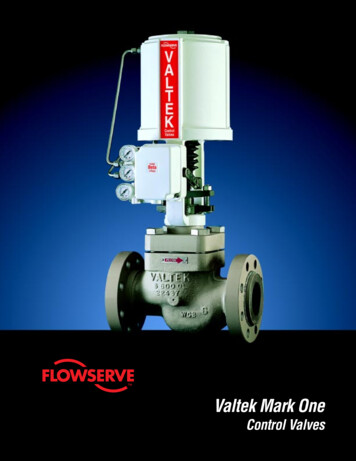
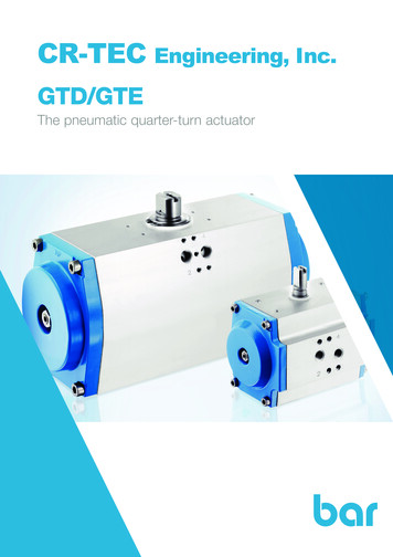
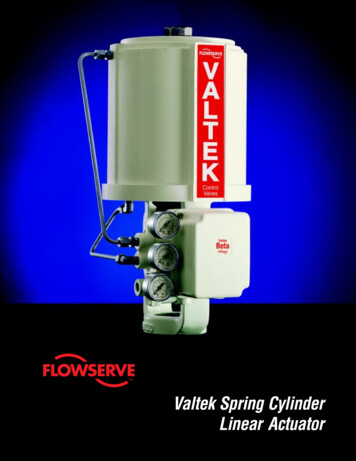
Valtek Spring Cylinder Linear ActuatorIntroductionAdjusting ScrewSpring ButtonAdjusting ScrewGasketSpringCylinderActuator StemLocknutPiston Stem O-ringStem SpacerPistonUpper Stem BushingPiston O-ringActuator Stem O-ringYoke O-ringCylinderRetaining RingStem BellowsOActuator StemStem ClampYokeLower Stem BushingStem Clamp BoltingSStroke PlateE0133Figure 1: Spring Cylinder Linear ActuatorThe Valtek spring cylinder linear actuator is a powerful,high-performance pneumatic actuator that providespositive throttling or on-off operation for automaticcontrol valves. Most cylinder sizes are designed forsupply pressures up to 150 psi (10.3 Bar).2Using a spring to provide fail-safe operation, this actuator is completely field reversible for air-to-open or air-toclose operation without additional parts. The positionersupplies air to both sides of the piston, providing stiff,precise movement and high-frequency response.
Valtek Spring Cylinder Linear ActuatorFeatures and AdvantagesImportant features and advantages of the Valtek spring cylinder linear actuator include:FeaturesAdvantagesMultiple positionersand controllersA variety of positioner/controller options makes the spring cylinder actuator ideal fora variety of control requirements.High frequencyresponseDouble-acting configuration responds quickly to signal changes.Dynamic positioningaccuracySupply pressure is sent to both sides of piston for stiff, precise actuator operation;small air volume between the piston and the bottom of the cylinder provides powerful pneumatic stiffness, allowing a high pressure drop – without plug slamming.Low air consumptionCylinder design uses less supply air than comparable diaphragm actuators.High thrust capability150 psi (10.3 Bar) operating pressure allows substantially higher thrust capabilitiesthan comparable diaphragm actuators. Higher thrust allows tighter valve shutoff.Longer strokesLonger strokes provide better process control. Size 25 spring cylinder linear actuators have a 11/2-inch (38 mm) stroke, in contrast to a 3/4-inch (19 mm) stroke on acomparable linear diaphragm actuator.Larger actuators have similar comparisons;stroke lengths are available up to 24-inches.Fail-safe springInternal spring provides fail-safe operation in the event of air system failure. Springbench set is not required.Compact andlightweightFor easier installation and maintenance, spring cylinder linear actuators aresubstantially lighter and more compact than comparable linear diaphragm actuators.Simple maintenancePeriodic maintenance is easy to perform since the spring cylinder actuator onlyrequires the removal of two parts to access all internal parts.Durable componentsHigh-quality materials require little maintenance; no diaphragm to rupture.Wide range of sizesStandard actuator sizes 25, 50 and 100 will handle thrust requirements for over95 percent of process applications; larger sizes up through size 600 are available forspecial applications.Fewer partsSpring cylinder linear actuators have one-third the number of parts as diaphragmlinear actuators; wear parts cost 10 percent of those for diaphragms, and lessinventory is required to maintain actuators.Field reversibleFailure mode is easily reversed without additional parts. Reduced inventory costs.No pressure regulatorrequiredCylinder actuators easily handle air supplies up to 150psi (10.3 Bar ) without apressure regulator and can be operated with as little as 30 psi ( 2.1 Bar )*.* Operating prexssure on some sizes is limited because of valve sizes.3
Valtek Spring Cylinder Linear ActuatorActuator StiffnessThe typical control valve operates with a constantlyfluctuating flow. As this dynamic force increases ordecreases, the control valve must remain in the samerelative position as dictated by the controller. To do this,the valve is dependent upon the actuator stiffness tominimize these position fluctuations.Actuator stiffness is defined as the ability of the actuatorto withstand suddenly changing dynamic fluid forcesacting on the valve trim.Since supply air pressure is delivered to both sides ofthe piston in the cylinder, the stiffness of the Valtekspring cylinder actuator is significantly greater than thatof a diaphragm actuator.The stiffness (spring rate) is equal to the expression:2K kPAvWhere:KkPA2v spring rate ratio of specific heat supply pressure piston area (in2) cylinder volume under pistonFor a 25 square-inch cylinder actuator (typical for a2-inch valve) with a supply air pressure of 100 psi (6.9Bar) and a 3/4-inch (19 mm) stroke, the spring rate wouldbe 9,333 lbs. per inch (1634 kN/m) at mid-stroke. Thebenefit of this principle is that as the volume under thepiston becomes smaller, the stiffness factor becomeslarger in a Valtek cylinder actuator. The equivalentdiaphragm actuator (46 square-inch) on the same valvewith a 3-15 psi (0-1 Bar) signal has a spring rate of only920 lbs. per inch (161 kN/m) at mid-stroke.The spring rate for a diaphragm actuator remains thesame, regardless of diaphragm position. When a valvewith a diaphragm actuator is operated close to the seatwith flow over the plug, sudden changes in the dynamicforce can cause the valve to slam shut. Diaphragmoperated valves have low-stiffness factors and arenormally installed with the flow under the plug.The stiffness of Valtek spring cylinder actuators actuallyincreases as the valve plug approaches the seat. Forexample: in a properly designed and assembled, 25square-inch cylinder actuator, with 100 psi (6.9 Bar)supply air pressure and the plug 1/8-inch (3 mm) off theseat, the piston is 3/16-inch (5 mm) from the bottom of thecylinder. At this point, the actuator generates a stiffnessof 18,667 lbs. per inch (3269 kN/m).4A spring cylinder actuated control valve may be operated with the flow over or under the plug, while maintaining precise throttling control. This can assist the actuator spring to fail in the required mode, thus increasingthe valve’s ability to shut off tightly.Thrust Producing CapabilityValtek linear spring cylinder actuators produce substantially higher thrust than comparable diaphragmactuators because the cylinder operates with supplypressures up to 150 psi (10.3 Bar). Throttling diaphragm actuators are limited to 40-60 psi (2.8-4.1Bar).Higher actuator air supply, coupled with high-pressureair on both sides of the actuator piston, provide exceptional stiffness for precise throttling control. Valtekcylinder actuator stiffness is sufficient to control highpressure drops and to permit the plug to throttle nearthe seat.Speed and SensitivityHigh air-handling capacity of the positioner, combinedwith relatively low cylinder volumes, produces faststroking speeds. High operating speed is achieved withvirtually no overshoot when approaching the final plugposition. Excellent static sensitivity is also acheived.For example, as little as 0.008 psi (0.0006 Bar) isrequired to move the stem 0.0005 inches (0.0127 mm)(the minimum detectable movement in the tests conducted) on a size 25 actuator. A signal change of only0.01 psi (0.0007 Bar) can reverse the stem motion.Table I shows typical stroking times. Increased strokingspeeds are available with Valtek flow booster valves.Table I: Typical Actuator Stroking TimesActuatorSizeTimes (seconds)For Maximum Stroke*1/4" Tubing3/8" 20020.818.4430031.327.74Actuation pressure: 60 psi (4.1 Bar)* Stroking time only (does not include time from receipt ofsignal and beginning of stem motion).
Valtek Spring Cylinder Linear ActuatorActuator PerformanceFrequency ResponseReversible Air ActionThe frequency response of Valtek cylinder actuators isextremely high – generally an order of magnitude better than comparable diaphragm actuator units. Suchresponse is achieved through a double-acting configuration that uses pressure on both sides of the piston.Standard cylinder actuators are supplied to provideeither air-to-open (air-to-retract) or air-to-close (air-toextend) action, with easy reversal in the field.With air-to-open action, the spring is installed on theupper side of the piston. For air-to-close action, thespacer and spring are installed on the underside of thepiston with the spring button stored on top of the piston.Size 25 Actuator, 9 psi 2 psi (0.62 Bar 0.14 Bar)03Relative Response dB6Degrees9120Phase ncy – HertzFigure 2: Frequency ResponseHysteresis and LinearityAn important characteristic of any actuator is its abilityto respond linearly to signal changes from the controllerand to give uniform response unaffected by decreasingor increasing pressures. Tests have shown the linearityof the cylinder actuator to be within 1.0 percent. Thesame tests showed that the difference in valve positionfor a given instrument signal, regardless of the requireddirection of change in the piston’s position, was small(refer to Table II on page 6 of the Beta PositionerTechnical Bulletin).Size 25 Actuator, Signal 4.2 to 13.8 psig(0.29 to 0.95 Bar)Input Signal13.8 psig(0.95 Bar)Signal4.2 psig(0.29 Bar)00.0onisitoePlvVa0.50Time extend(Air-to-close)E0136Figure 4: Spring Cylinder Air ActionTable II: Actuator SpecificationsTypeCylinder with positive spring actionSizes25, 50, 100, 200, 300, 400, 500, 600 sq. in.Spring DesignsSingle (std.) and dualActionField reversible: Air-to-open, Air-to-closeOperatingpressureUp to 150 psi (10.3 Bar)Temperaturerange-40O to 350O F*(-40O to 177O C*)* Ambient temperatures greater than 180O F (82O C) require VitonO-rings. Ambient temperatures below -40O F (-40O C) requirefluorosilicone O-rings. (Viton is a reg. trademark of E.I. DuPont.)Figure 3: Step Test5
Valtek Spring Cylinder Linear ActuatorSpring Cylinder ConstructionSizesSpring cylinder linear actuators are available in four standard sizes: 25, 50 and 100 square-inches (nominal pistonarea) and five oversized actuator sizes: 200, 300, 400, 500and 600 square-inch. The 400 and 600 sizes have atandem, double piston configuration.Piston O-RingPistonStandard Materials of ConstructionThe cylinder and piston are made of corrosion-resistantanodized aluminum. A tough ductile iron yoke is used towithstand impact. The exposed actuator stem is stainlesssteel and is guided by oilite bronze bushings. For service inextremely corrosive atmospheric conditions, the yoke,cylinder, clamps and other exposed parts can be suppliedin stainless steel or the actuator can be completely coatedin neoprene. (Stainless steel clamps, bolts, nuts and yokesare available from stock.)Table III: Materials of ConstructionPartYokeYoke clampYoke clamp boltsStem clamp*Stem clamp nut and boltCylinder retaining ringActuator stemStem spacerActuator stem lock nutO-ringsSpringSpring buttonAdjusting screwPistonCylinderCylinderMaterialPhosphated, painted ductile ironStainless steelZinc plated steelPhosphated, painted ductile ironZinc plated steelZinc plated steel416 stainless steelAluminumZinc plated steelBuna-NAlloy steelPainted steelZinc plated steelAnodized aluminumPainted anodized aluminumE0137Figure 5: Piston SealThe piston is sealed with a Buna-N O-ring. Thecylinder bore is smoothly finished for long servicelife, and the cylinder walls are lubricated with DowCorning 55MTM grease. This lubricant is not solublein water or oils that may be present in the air supplyand is effective over a wide temperature range from-50 to 350 F (-46 to 177 C). If ambient temperatures are expected to exceed 120 F (49 C), aspecial Viton O-ring can be supplied. Tests demonstrate service life in excess of five million strokeswith zero or negligible leakage. Piston O-rings usedin these actuators have proven successful in continuous service for more than 20 years.CylinderYoke O-Ring*Denotes stainless steel material on 25 and 50 sq.in.Table IV: Valtek Cylinder ylinder UpperLowerMax.Vol.Bore Cylinder CylinderStemStemOverDia.AreaAreaDiameter AreaPiston(in.)(sq. in.) (sq. in.)(in.)(sq. in.) (cu. 873733303355195661*Used as oversized actuators in place of the next smaller actuator**Tandem, double piston configuration6CylinderRetainingRingYokeE0138Figure 6: Cylinder to Yoke AttachmentThe cylinder is attached to the yoke with a solid,square retaining ring. Removal can be accomplishedsimply with the aid of two screwdrivers (refer toValtek Installation, Operation, Maintenance Instructions 2 for correct disassembly procedures.) A staticO-ring seal is located at the cylinder bore andactuator stem.
Valtek Spring Cylinder Linear ActuatorActuator SpringsTable V: Cylinder Actuator Spring es)3STDSTDSTDDUALDUALRatelb/in (N/m)180180180447447Spring Ext.lbs (N)Spring Ret.lbs L885154987* Heavy spring includes outer spring of dual spring 2SpringDesignAir-to-close(Air-to-extend)Spring Ret.lbs (N)Spring Ext.lbs 3736702335Because of the unique, four-way, double-acting design, Valtekcylinder actuators do not require springs for positioning. Thespring serves only as a fail-safe device. Although valve flowdirection usually assists the actuator on loss of air, normally thespring is designed to achieve the fail position independently.Proper sizing of the cylinder spring requires an understanding ofthe specific spring force listed in the table above.AdjustingScrewDual Spring Actuator ConstructionSpring GuideDual springs are available for heavy duty service in theair-to-retract (air-to-open) configuration only. Retrofitting a standard cylinder actuator to dual springs requires only five additionalparts: a new actuator stem, a spring button, the inner spring, theouter spring, and a spring guide. Valves equipped with dualspring actuators are not field reversible and require a minimumof 60 psi (4.1 Bar) supply air to compress the springs.Spring ButtonOuter SpringInner SpringOSE0139Figure 7: Dual Spring Actuator7
Valtek Spring Cylinder Linear ActuatorSide-mounted Continuously Connected HandwheelsCylinder can bedisassembledwhile handwheelsecurely holds valve inpositionLocking bar securelylocks handwheelsetting.High load capacityangular contactbearings supportshaft with minimumfriction.OPENNEUEfficient threaddesign required lesstorque, permits easieroperationVisible neutralposition indicatorSize 25, 50, 100 and 200E0140Figure 8: Side-mounted Continuosly Connected HandwheelsThe Valtek side-mounted handwheel is a continuouslyconnected, declutchable design that permits manualoperation of linear actuators. The standard for valveswith up to a four-inch stroke, it is especially convenientduring start-up, in emergencies, or due to air failure.2. Convenient access allows operator to turn thehandwheel easily in a more natural position.Its efficient design utilizes heavy-duty, anti-frictionbearings that allow high thrust with low torque on thehandwheel. The side-mounted handwheel provides themechanical advantage needed for manual operationand an effective means to overcome the fluid forces orfriction within the valve during manual operation.Due to the continuously connected design, the handwheel can act as a high or low-limit stop. By effectivelyisolating the actuator stem from the actuator, the continuously connected handwheel permits positioner andactuator maintenance without interruption of service.Other advantages characterize side-mounted design:1. The pneumatic spring cylinder can be disassembledwhile the handwheel holds the valve in position onfail-open valves. On fail-closed valves, the valvemust be closed.83. Easy adaptation to a chain-driven mechanism ispossible.The side-mounted handwheel features a highly visible,neutral-position indicator and comes standard with alocking bar.A three-way bypass valve is installed in the positionersupply line to shut off the air supply or neutralize pressureacross the piston when operating the valve manually.
Valtek Spring Cylinder Linear ActuatorSide-mounted Continuously Connected HandwheelsTable VI:Standard Materials of ConstructionSize 25, 50, 100 and 200PartMaterialYokeDuctile ironActuator stem pinStainless steel (hardened)Crank lever4130 alloy steel (heat treated)Crank pivot pin416 stainless steelDrive nutAluminum bronze*Handwheel shaft(ACME screw)416 stainless steel*HandwheelAluminum/Tubular SteelHousingDuctile iron*Coated with electro film lubricantSide-mounted auxiliary handwheel on a size 25 Linear Actuator.Table VII: Side-mounted Continuously Connected Handwheel eterinmmHWTurns 2290132246108.0.31126:14.0102395179Table VIII: Top-mounted Continuously Connected Handwheel 0/8.0 152/203 2851292002.62-4.75100/2001845512305128:16.0/8.0 152/203 400181(1) 100 psi (6.89 Bar) maximum supply pressure when 50-inch HW Operator is used on a 100-inch actuator.Example: if you apply 50 lb (222 N) rim pull on the 12-inch (305-mm) handwheel of a 50-inch HW operator, then the operator output will be:50 lb (222 N) rim pull x 63 3150 lb (14011 N) output thrust.9
Valtek Spring Cylinder Linear ActuatorTop-mounted HandwheelsTop-mounted handwheels can be mounted on size 100or larger actuators. Two types are available: continuously connected and push-only.E0021Figure 10: Push-only HandwheelTurning the handwheel clockwise drives the handwheelstem down to extend the actuator stem. This handwheelcan be used to limit upward travel.E0028Figure 9:Continuously Connected HandwheelContinuously connected handwheels are highly versatile. They can be used to retract or extend the stem andact as either a high or low-limit stop. A simplified designmakes it easy to place the handwheel in a neutralposition for automatic operation of the actuator.This ruggedly built handwheel utilizes a precision-madebevel gear sealed in a weatherproof housing to maximize performance. High-thrust output can be achievedwith low-torque input on the handwheel. Consult thefactory on capacities for specific applications.In operation, the handwheel is turned counterclockwiseto move the handwheel screw against the stem locknut,retracting the stem. Moving the handwheel clockwiseturns the handwheel screw down against the shoulderon the stem, forcing the stem to extend. Returning thehandwheel screw to the neutral position (top of thescrew even with a neutral line as seen through thetransparent cap liner) permits operation of the actuatorwithout interference from the handwheel. Adjusting thehandwheel screw to a position other than neutral provides a limit stop to limit travel in either direction.10OSE0023Figure 11: Actuator Limit StopsSimple actuator stops are available to limit either opening or closing of the valve. Handwheels are not provided, and locknuts are included to maintain precisesetting of the selected limit stop position.
Valtek Spring Cylinder Linear ActuatorLever and Handwheel ActuatorsValtek cylinder-operated lever actuators can beused to automatically position dampers, louvers,variable pitch fans and to make other mechanicaladjustments to process machinery. Lever actuator designs are available for size 25, 50 and 100cylinders.ValtekBetaE0025Figure 12: Lever ActuatorsTABLE IX: Lever Actuator ForceCyl.SizeLeverTravelin mm4 1025 1276 1527 178258 2039 22910 25411 27912 3056 1527 1788 203509 22910 25411 27912 30512 305100 16 40620 50824 610Available Force (lb / N) atSupply Pressure (Psig / Barg)805.5100 6.9150 10.3621 2762 776 3452 1164 5178496 2206 621 2762 932 4146414 1842 518 2304 776 3452355 1579 444 1975 665 2958311 1383 388 1726 582 2589276 1228 345 1535 518 2304248 1103 311 1383 466 2073226 1005 282 1254 423 1882207 921 259 1152 388 17261311 5832 1639 7291 2458 109341124 5000 1405 6250 2107 9372983 4373 1229 5467 844 8203874 3888 1093 4862 1639 7291787 3501 983 4373 1475 6561715 3180 894 3977 1341 5965656 2918 819 3643 1229 54671428 6352 1852 8238 2913 129581071 4764 1389 6179 2184 9715857 3812 1111 4942 1747 7771714 3176 926 4119 1457 6481E0123Figure 13: Manual HandwheelsManual handwheels are available wherever anultra-high-performance, manual operation is required. Rising-stem design handwheels are sizedfor easy operation and the handwheel yoke isdesigned to be interchangeable with cylinder ordiaphragm actuators.Table X:Manual Handwheel SpecificationsHandwheelSize*2550100Body SIze(Class 150 600) inches1/2 - 2HandwheelDiameterinches (mm)Thrust@50 lb (222N)Rim Pull9 (STD)230202412 (OPT)3052699 1200890033-412 (STD)30521876 (Class 150)18 (OPT)4553280 145906 (300 & 600)18 (STD)4552180thru 824 (OPT)6102907 1293197289697* Handwheel size is comparable to standard actuator size.11
Valtek Spring Cylinder Linear ActuatorAuxiliary EquipmentAir Filters are required for installation upstream of thepositioner. They feature high flow capacities and handleup to 150 psi (10.3 Bar) supply air pressure. Easyaccess to the large drip well permits inspection andreplacement of the filter cartridge, while the integraldrain valve allows removal of trapped oil, moisture andother foreign material. Regulators are usually not required with Valtek actuators and positioners.Position Pac is a position transmitter that exceeds thecapabilities of normal limit switches by providing acontinuous, electrical output signal in proportion to theposition of a control valve. Position Pac operates withtwo wires on a 4 to 20 mA DC voltage, ensuring infiniteresolution for safe, dependable monitoring of a controlvalve’s position to within linearity 1 percent. Mountedon the actuator, the infinite resolution potentiometer iseasily adjusted with zero and span settings for fieldcalibration. Position Pac models may contain a potentiometer and transmitter, two or four limit switches or acombination of a transmitter and two limit switches. Arugged aluminum housing provides weather and explosion-proof protection from external conditions.Figure 14: Position PacFlow boosters are used on throttling control valves toprovide fast stroking action with large input signalchanges. At the same time, the flow boosters allownormal positioner air flow (and normal actuation) withsmall changes in the positioner input signal. Dependingon actuator size, packing set and the number used,boosters can decrease valve stroking times up to 90percent.Limit switches can be conveniently mounted to electrically indicate open, closed, or intermediate positions ofthe valve stroke. Each switch is firmly mounted on theyoke, with the switch arm contacting an ear on the stemclamp to sense valve position. Single pole or doublepole, double-throw switches are available in explosionproof, hermetically sealed or weatherproof housings.Figure 15: Flow BoostersThree-way solenoids are used to interrupt an instrument signal to a pneumatic positioner or to operate aspring diaphragm valve.Four-way solenoids are used on spring cylinder actuators for on-off operation only, insuring fast, positive,two-directional action. Available in a wide variety ofoperation voltages for both AC and DC, solenoids arestandard equipment with a class F coil for continuousduty at temperatures up to 155O F (68O C).12Figure 16: Limit Switches
Valtek Spring Cylinder Linear ActuatorCylinder SystemsOccasionally, some applications require greater actuator spring forces than standard or dual springs canprovide. In such cases, building special, extra-strongfailure springs may be mechanically difficult and economically unfeasible. The air spring is designed tosolve many such problems.Air springs, which provide a locked-up volume of air todrive the actuator in the failure direction, are usedprimarily to close valves upon air failure. A fail-closedValtek valve is customarily operated with the flowdirected over the plug. Thus, with the plug on the seat,the upstream pressure acts to hold the valve closed. Airsprings on Valtek valves work only during the instant ofair failure to drive the valve to the closed position.Process line pressure will insure the valve stays closed.Air Spring Using Cylinder VolumeUtilizing the stored volume within the cylinder itself forfailure protection, an air spring is a common fail-safesystem. In this case, the valve positioner is operated asa three-way valve positioner to supply air only to theunderside of the piston. A three-way switching valvesenses air supply pressure. When pressure drops to apredetermined value, the switching valve locks the airon the upper side of the piston to drive the valve closed.With full air supply pressure to the three-way switchingvalve, an airset regulates the proper amount of airpressure to the upper side of the IRSETOUTPUT 2 (PLUGGED)AIRSUPPLYOUTPUT 1INSTRUMENTSIGNALSUPPLYPOSITIONERFigure 17:Air Spring Using Cylinder VolumeINACTUATORCYLEXHLOCK-UPVALVE(Normally Open)CHECK WAYSWITCHINGVALVEAIRSUPPLYOUTPUT 2INOUTPUT 1EXHVENTINSTRUMENTSIGNALSUPPLYPOSITIONER* .031 dia. bleed orificeFigure 18:Air Spring With External Volume Tank(Plugged)EXHACTUATORCYLINLOCK-UPVALVE(Normally PVALVEFail-in-place Lock-up SystemThe purpose of this system is to hold the actuator in thelast operating position upon air failure. A 3-way switching valve is used to sense air supply. Upon failure of theair supply, this valve operates to exhaust the signalconnections to two lock-up valves. The lock-up valveshold the existing pressure on both sides of the piston;thus, locking it in place.B(Normally Closed)CYLAir Spring with External Volume TankIf the volume on the top of the cylinder is insufficient tocause the valve to fully stroke upon air failure, anexternal volume tank is used to supply the additionalvolume required. This system requires a small lock-upvalve in the air supply to each side of the cylinder. Thelock-up valve on the bottom of the piston operates toexhaust upon failure. The lock-up valve on the top sideof the cylinder admits volume tank air to the cylinderupon air failure. The volume tank can be sized asrequired.C(Normally Closed)OUTPUT 2INCYLOUTPUT 1EXH(Plugged)INSTRUMENTSIGNALSUPPLYPOSITIONER* .062 dia. bleed orificeE0141Figure 19: Fail-in-place Lock-up System13
Valtek Spring Cylinder Linear ActuatorDimensionsN(Lifting ring available onsizes 25 and 50 HLINEE0083With Top-mountedContinuously Connected HandwheelStandard Cylinder ActuatorWith Push-onlyHandwheelTable XI: Standard Actuator and Handwheel (inches / mm)CylinderSize(sq.in.)25Body Size(inches)Class125 - 600100Std.K**L**M***NCont.Conn.PushOnly1/2 to 12.0014.7 373––17.4 4426.5 1657.4 189 4.9 1249.0 229––11/2 to 12.0018.8 478––27.0 6869.1 2328.7 221 4.6 118 12.0 305––1––29.3 7439.1 2326.6 168 4.6 118 12.0 305––/2 to 23 to 4,6 (Class 150)1 /2 to 22.6221.1 5353 to 4,6 (Class 150)11/2 to 22.62 - 2.8826.0 66045.0 1143 40.1 1019 12.5 3186 to 8,10 to 12(Class 150)3 to 43.3827.0 68646.0 1168 41.1 1044 12.5 318 10.4 264 4.2 105 18.0 457 16.0 40610 to 146 and larger9.9 252 4.5 114 18.0 457 16.0 4064.00 - 4.7527.0 68646.0 1168 46.1 1044 12.5 318 10.8 273 4.2 105 18.0 457 16.0 406/2 to 22.62 - 2.8826.6 67645.6 1159 40.7 1034 17.5 4456 to 8,10 to 12(Class 150)3 to 43.3827.6 70246.6 1184 41.7 1059 17.5 445 10.4 264 4.2 105 18.0 457 16.0 40610 to 146 and larger4.00 - 4.7527.6 70246.6 1184 41.7 1059 17.5 445 10.8 273 4.2 105 18.0 457 16.0 4063006 and larger 6 and larger3.38 - 4.7530.5 77454.1 1373 ******** 21.8 552 11.1 283 4.1 105 18.0 457 16.0 4064006 and larger 6 and larger3.38 - 4.7536.6 93056.7 1439 ******** 18.0 457 10.7 272 4.5 114 18.0 457 16.0 4065006 and larger 6 and larger3.38- 4.7531.0 787************** 28.0 711 11.1 283 4.1 105 18.0 457 16.0 4066006 and larger 6 and larger3.38 - 4.7545.8 1163************** 21.8 552 11.1 283 4.1 105 18.0 457 16.0 4063 to 4,6 (Class 150)2001* 100 sq. in. and larger, 4-inch maximum stroke. Consult factory.** For Beta I/P or XL positioner add 2.0 inches (52 mm) to "L"dimension and 1.8 inches (45 mm) to "K" dimension.14JTop-mountedHandwheel1/2 to 250Class900 - 2500G*SpudDiameter(inches)9.9 252 4.5 114 18.0 457 16.0 406*** Standard size shown. Handwheel diameter subject tochange per torque requirements.**** Consult factory.
Valtek Spring Cylinder Linear ActuatorDimensionsMN(Lifting ring available onsize 25 and 50 only)GOPENNEUValtekBetaRMATCHLINEKE0084Table XII: Side-mounted Continuously Connected Handwheel*With Size 25, 50, 100 and 200 (inches / mm)CylinderSize25Body Size ratorSize/
Valtek Spring Cylinder Linear Actuator 2 O S E0133 The Valtek spring cylinder linear actuator is a powerful, high-performance pneumatic actuator that provides positive throttling or on-off operation for automatic control valves. Most cylinder sizes are designed for supply pressures up to 150 psi (10.3 Bar).