Transcription
BBC Microcomputer service manualSECTION 1 BBC Microcomputer Models A and B (ANA01 - ANB04)SECTION 2 BBC Microcomputer Model B (ANB51 - ANB54)SECTION 3 Additional Upgrades1770 Disc interface daughter board upgrade64K Sideways RAM upgradePart No. 0433,001Issue 1October 1985
Within this publication the term 'BBC' is used as anabbreviation for 'British Broadcasting Corporation'.Copyright ACORN Computers Limited 1985Neither the whole or any part of the information contained in,or the product described in, this manual may be adapted orreproduced in any material form except with the prior writtenapproval of ACORN Computers Limited (ACORN Computers).The product described in this manual and products for use withit, are subject to continuous development and improvement. Allinformation of a technical nature and particulars of the productand its use (including the information and particulars in thismanual) are given by ACORN Computers in good faith. However, itis acknowledged that there may be errors or omissions in thismanual. A list of details of any amendments or revisions to thismanual can be obtained upon request from ACORN ComputersTechnical. Enquiries. ACORN Computers welcome comments andsuggestions relating to the product and this manual.All correspondence should be addressed to:Technical EnquiriesACORN ComputersLimited NewmarketRoadCambridgeCB5 8PDAll maintenance and service on the product must be carried outby ACORN Computers' authorised dealers. ACORN Computers canaccept no liability whatsoever for any loss or damage caused byservice or maintenance by unauthorised personnel. This manual isintended only to assist the reader in the use of this product,and therefore ACORN Computers shall not be liable for any lossor damage whatsoever arising from the use of any information orparticulars in, or any error or omission in, this manual, or anyincorrect use of the product.This manual is for the sole use of ACORN Computers' authoriseddealers and must only be used by them in connection with theproduct described within.First published 1985Published by ACORN Computers Limited
SECTION 1 BBC Microcomputer Models A & B
BBC Microcomputer Service ManualContents1 Introduction1.1Nature and purpose of the manual1.2Technical specification1.2.1 Model A specification1.2.2 Model B specification 1.2.3 Expansion1.2.4 Software1.2.5 Machine operating system 1.2.6 BASIC1.3Packaging1.4Mechanical assembly of the case etc2 2.12.2General Circuit DescriptionIntroductionHardware description3 d Circuit DescriptionsProcessor clock circuitry reset circuitryMemory address decodingDRAMs CRT controller video processor Teletext hardwareRGB PAL encoder UHF outputCassette RS423 serial processorInternal VIAKeyboardSound speech serial ROM interfacesA to D convertersDisc interfacePrinter user port interfacesEconet1 MHz bus 3.14 Power supply4 4.14.24.34.44.54.64.7Upgrading the PCBConvert from EPROM MOS to ROM MOSConvert model A to model BAdd speech optionAdd 5 1/4 inch disc interface to model BAdd Econet interface to model AAdd 8 inch disc interface to model BPartial upgrading5 5.15.25.35.3.15.3.25.3.3Selection links & Circuit changesSelection link surveyTable of link optionsCircuit modifications from Issue 1 to Issue 7Changes from issue 2 to 3Changes from issue 3 to 4Changes from issue 4 to 7
6 6.16.26.36.46.56.5.16.5.2Servicing Fault-findingIntroductionTest equipmentFault isolationMost common faultsTest programs sample waveformsTest programTest ROM7 7.17.27.3Interfacing SurveyPurpose of each interfaceInterfacing to various printersHardware hints and tips8 8.18.28.38.48.58.6Component location tablesIntegrated circuitsTransistorsDiodesCapacitorsResistorsLinks9 9.19.29.39.49.5AppendicesCircuit block diagramAssembly DrawingCase Lower Assembly DrawingMain PCB LayoutMain PCB Circuit DiagramIssue 9 (issue 7 board) as full foldoutKeyboard Circuit DiagramPower Supply Circuit DiagramParts list for B disc EconetGlossary of abreviations9.69.79.89.9
WARNING: THE COMPUTER MUST BE EARTHEDIMPORTANT: The wires in the mains lead for the computer are colouredin accordance with the following code:GREEN & YELLOW - EARTHBLUE - NEUTRALBROWN - LIVEAs the colours of the wires may not correspond with the colouredmarkings identifying the terminals in your plug, proceed as follows:The wire which is coloured green and yellow must be connected to theterminal in the plug which is marked by the letter E, or by the safetyearth symbol , or coloured either green or green and yellow.The wire which is coloured blue must be connected to the terminalwhich is marked by the letter N, or coloured black.The wire which is coloured brown must be connected to the terminalwhich is marked by the letter L, or coloured red.If the socket outlet available is not suitable for the plug supplied,the plug should be cut off and the appropriate plug fitted and wired aspreviously noted. The moulded plug which was cut off must be disposedof as it would be a potential shock hazard if it were to be plugged inwith the cut off end of mains cord exposed.The moulded plug must be used with the fuse and the fuse carrier firmlyin place. The fuse carrier is of the same basic colour* as the colouredinsert in the base of the plug. Different manufacturers' plugs and fusecarriers are not interchangeable. In the event of loss of the fusecarrier the moulded plug MUST NOT be used. Either replace the mouldedplug with another conventional plug wired as previously described, orobtain a replacement fuse carrier from an authorised BBC Microcomputerdealer. In the event of the fuse blowing, it should be replaced, afterclearing any faults, with a 3 amp fuse that is ASTA approved to BS1362.This computer was designed and manufactured to comply with BS 415. Inorder to ensure the continued safety of Acorn products, power suppliesshould be returned to Acorn for repair.Do not use the Microcomputer in conditions of extreme heat, cold,humidity or dust or in places subject to vibration. Do not blockventilation under or behind the computer. Ensure that ,no foreignobjects are inserted through any openings in the Microcomputer.*Not necessarily the same shade of that colour.
1 Introduction1.1 Nature and Purpose of the ManualThe purpose of this manual is to provide technical and diagnosticinformation about the BBC Microcomputer.After giving general information about the technical specification andthe mechanical assembly of the BBC Microcomputer, it gives a detaileddescription of the operation of the whole of the circuit. Informationis also given about how to upgrade the various models of microcomputerand the purpose of the various links on the circuit board. Some detailsare also given of the ways in which the circuit has changed in itsevolution from issue 1 up to issue 7. There is some guidance aboutservicing and fault-finding, further information about interfacing anda few suggestions about possible applications. Finally there is asection of hardware hints and tips which is a compilation of ideas fromvarious sources.1.2 Technical SpecificationThe BBC Microcomputer is supplied with two levels of hardwareprovision, designated, model A and model B, the former being fullyupgradable to the latter.1.2.1 Model A SpecificationA fast, powerful self-contained computer system generating highresolution colour graphics and capable of synthesising 3 part music 1channel of noise. The computer is contained in a rigid injectionmoulded thermoplastic case. The following are contained within thecomputer thus ensuring the minimum of connecting wires.* 73 key full travel QWERTY keyboard including 10 user definablefunction keys. The keyboard has two key rollover and auto repeat.* Internal power supply is fully encased and manufactured to BS 415Class 1.* The internal loudspeaker is driven from a 4-channel sound synthesiscircuit with full ADSR envelope control.* A colour television signal, for connection to a normal domestictelevision aerial socket, is available through a phono connector. Thissignal is 625 line, 50Hz, interlaced, fully encoded PAL and ismodulated on UHF channel 36.* A BNC connector supplies a composite video output to drive a blackand white or PAL colour monitor.* A standard audio cassette recorder can be used to record computerprograms and data at 300 or 1200 baud using the Computer Users TapeStandard tones. The cassette recorder is under full automatic motorcontrol and is connected to the computer via a 7 pin DIN connector.1
* An interrupt driven elapsed time clock enables real-time controland timing of user responses.* The unit uses a 2 MHz 6502A and includes 16K of Random Access Memory.* A 16K Read Only Memory (ROM) integrated circuit contains a MachineOperating System designed to interface easily to high level languages.* A further 16K Language ROM contains a fast BASIC interpreter. Theinterpreter includes a 6502 assembler which enables BASIC statements tobe freely mixed with 6502 assembly language.* Up to four 16K "sideways" ROMs may be plugged into the machine atany time. These four ROMs are "paged" and may include Pascal, wordprocessing, computer aided design software, disc and Econet filingsystems or Teletext acquisition software.* The full-colour Teletext display of 40 characters by 25 lines, knownas mode 7, has character rounding, with double height, flashing,coloured background and text plus pixel graphics - all to the Teletextstandard.* The non-Teletext display modes (modes 0 to 6) provide user definablecharacters in addition to the standard upper and lower case alphanumeric font. In these modes, graphics may be freely mixed with text.Text characters can be positioned not only on, for example, a 40 x 32grid, but at any intermediate position.* Separate or overlapping text and graphic windows can be easily userdefined over any area of the display. Each of these windows may befilled separately and the text window scrolls independently of the restof the screen.* The Model A is able to support the following modes:ModeModeModeMode4:5:6:7:320 x 256, 2 colour graphics and 40 x 32 text (10K)160 x 256, 4 colour graphics and 20 x 32 text (10K)40 x 25, 2 colour text only (8K)40 x 25, Teletext display (1K)* All graphics access is "transparent" (see section 2.2), resulting ina fast, snow-free display.* Extensive support is provided in the Machine Operating System forthe graphics facilities, and this is reflected in the BASICinterpreter. These facilities include the ability to draw lines veryrapidly and to fill large areas of colour. In addition, very rapidchanges of areas of colour can be effected by the use of a colour "palette".* The Model A BBC Microcomputer can be expanded at any time to theModel B. In addition, or as an alternative, other facilities such asthe Econet may be fitted within the computer system.2
1.2.2 Model B SpecificationThe Model B BBC Microcomputer is an enhanced version of the Model AMicrocomputer with the following differences:* 32K Random Access Memory (RAM). This enables the following extragraphics modes to be used:ModeModeModeMode0:1:2:3:640 x 256,320 x 256,160 x 256,80 x 25, 22 colour graphics and 80 x 32 text (20K)4 colour graphics and 40 x 32 text (20K)16 colour graphics and 20 x 32 text (20K)colour text only (16K)* The installed RAM is divided between the high resolution graphicsdisplay, the user's program and Machine Operating System variables. Ifhigher resolutions are required with large programs, then the secondprocessor option may be fitted.* 6 pin DIN connector provides separate RGB and sync outputs at TTLlevels. RGB are all high true, and sync is link selectable as high orlow true, pulse duration 4.7 microseconds.* Serial interface to RS423 standard. The new standard has beendesigned to be inter-operable with RS232C equipment but offers aconsiderably enhanced specification - for example in maximum length ofcable and maximum data transfer rates. Baud rates are softwareselectable between 75 baud and 9600 baud. The interface provides notonly two-way data transfer, but also two-way hand-shaking using RTS andCTS lines. The software for implementing this interface is onlyprovided with operating systems 1.2 onwards.* An 8 bit input/output port with 2 control bits is also provided.* Four analogue input channels are provided. Each channel has an inputvoltage range of 0 - 1.8V. The conversion time for each channel is 10milliseconds. These analogue inputs can be used not only as inputs forgames-paddles or joysticks but also in laboratory control situations.The resolution of the ADC chip is 12 bits, but its conversion is suchthat only 9 or 10 bits are significant. However with suitableaveraging, this can be extended to the full 12 bits accuracy.* A 1 MHz buffered extension bus is provided for connection to avariety of external hardware such as a Teletext acquisition unit, IEEE488 interface, Winchester disc drive etc.3
1.2.3 ExpansionThe following expansion options are available, some of which may befitted internally at purchase, but all of which could be fitted byDealers at a later date:* Floppy disc interface (fitted as an option at purchase)* Econet network interface (fitted as an option at purchase)* Voice synthesis circuit with cartridge ROM pack interface* Various alternative high-level languages in ROMExternal options which plug directly into the machine include:* Games paddles* Cassette Recorder* Black and White and colour monitors and televisions* 5 1/4" disc drives, ranging from single-sided single density (100K)to dual double sided double track density (800K).* Dot-matrix or daisy wheel printers, serial or parallel interface* Teletext acquisition unit enabling Tele-software to be downloadedinto the BBC Computer as well as providing access to the normalTeletext services. Pages may be "grabbed" and stored for later use.* 3 MHz 6502 second processor with 64K of RAM.* Z80 second processor with 64K of RAM and a fully CP/M-compatibleoperating system.* IEEE interface* Winchester 10 megabyte disc drive* Prestel adaptor unit1.2.4 SoftwareConsiderable attention has been paid to the overall design of bothsystems and applications software. A modular approach has been adoptedspecifically to ease the interfacing of various high-level languages (such as BASIC and Pascal) to the operating system.1.2.5 Machine Operating SystemA 16K ROM is used for the MOS. This software controls all input/outputdevices using a well defined interface. The MOS supports the followinginterrupts (the full implementation only being available from MOS 1.2onwards):* Event Timer (10ms) (used as an elapsed time clock)* 4 channel analogue to digital converter* Vertical sync* Keyboard and keyboard buffer* Music tone generation and buffer* Serial interface, input and output buffers* Parallel input/output portand 'hooks' are provided to support other devices such as:* Teletext acquisition* Prestel acquisition* Econet file system* Disk file system* Byte transfer to second processorThe majority of the operating system calls are vectored to enable theuser to change them if required.4
1.2.6 BASICThe BASIC interpreter is an extremely fast implementation, withnumerous powerful extensions:* Long variable names* Integer, floating point and string variables* Multi-dimension integer, floating point and string arrays* Extensive support for string handling* IF . THEN . ELSE* REPEAT . UNTIL* Multi-line integer, floating point and string functions* Procedures* Local variables* Full recursion on all functions and procedures* Effective error trapping and handling* Cassette loading and saving of programs and data* Full support for the extensive colour graphics facilities* Easy control of the built-in music generation circuits* Built-in 6502 mnemonic assembler enabling BASIC and assembler to bemixed, or pure assembly language programs to be produced.1.3 PackagingThe BBC Microcomputer is supplied in a two part moulded polystyrenepacking which is further packaged within a cardboard sleeve. With theMicrocomputer, a User's Manual, a Welcome Cassette package and a UHF TVlead are also supplied. The packaging should be kept intact in case itbecomes necessary to transport the unit at a later date.1.4 Mechanical assembly of case etcThe lid of the Microcomputer case may be removed after undoing fourfixing screws, two on the rear panel and two underneath. Whenreassembling, press the lid down at the rear whilst tightening the tworear fixing screws. Take care not to lose the two spire clips pushedonto the case lid, into which the rear fixing screws locate. NB Do notremove the lid with the mains power connected.Inside the Microcomputer are three main sub-assemblies:power supply unit, keyboard and the main printed circuit board.To remove the keyboard, undo the two or, in some cases, three screwsand nuts holding it to the case bottom, take care to note the positionsof the associated washers. Unplug the 17 way keyboard connector and the2-way loudspeaker connector from the main printed circuit board, andthe 10 way serial-ROM connector, if fitted.The power supply unit is connected to the main circuit board by sevenpush-on connectors which may be unplugged. Three screws on theunderside of the case are undone allowing the unit to be removed. Onreassembly, ensure that the same type of screw is used.The main printed circuit board can be removed after the two wires toSK2 (composite video BNC socket) have been disconnected. Undo the fourfixing screws (five or seven screws on later issue boards) and removethe circuit board from the case by sliding it forwards and then liftingit from the rear.5
2 General Description of Hardware2.1 IntroductionThis next section gives a general description of the hardware of thecomputer, and reference is made to the functional block diagram (section 9.1) which is laid out approximately as the components aresituated on the printed circuit board. General areas and componentorientations are referred to by using compass points, as shown on theblock diagram. When any reference needs to be made to the specificposition of a component, then X-Y co-ordinates will be used, giving thedistances in millimetres from the SW corner. This is also shown on theblock diagram. A list is given in section 8 of this manual of all theintegrated circuits, transistors, diodes, capacitors, resistors andselection links by number, including their X-Y co-ordinates on the PCBand on the main circuit diagram.As each section of the hardware is described, reference is made tosections of the following chapter in which more detailed descriptionsare given. The heart of the hardware is the 6502 microprocessor, and inthis general description we shall move around 'he 6502 in an anticlockwise direction starting from the SE corner c the PCB.2.2 Hardware descriptionThe 6502 accesses an area of just less than 32 Kbytes of ROM. (3/4K ofthis memory allocation is actually used for memory-mapped input/output.)The ROM is arranged in such a way that one group of 16K bytes forms afixed part of the memory map (15 1/4K ROM for the operating system 3/4K of I/O), whilst the other 16K has been organised to give as muchflexibility as possible. There is a ROM select facility for accessingup to 16 different memory devices, although only four sideways ROMsockets are available on the PCB. It is expected that the normal way inwhich these four sockets will be used is to provide 2 MHz access toeach of 4 chips which could be either 16K or 8K, ROMs or EPROMs. [Seesection 3.2]The RAM is also divided into two sections of 16 Kbytes, each of whichcontains eight 16K by 1 bit DRAM chips. In the model A microcomputer,only one bank of 16K is present whilst both are present in the model B.This RAM has to be accessed by both the processor itself and also theCRT controller. This is done by using a form of "transparent access" inwhich both the processor and the CRT controller can access the RAM atthe full clock speed by interleaving the accesses on alternate phasesof the system clock. [See section 3.3]The display is extremely versatile, and uses two entirely differentmethods depending on screen mode. Mode 7 uses Teletext hardware whichproduces RGB signals by having its own character generator and acceptingdata from the RAM as ASCII characters. This means that it uses verylittle RAM (only 1 Kbyte), and apart from providing the addressing forthe RAM, the only thing which the CRT controller has to do is to addthe cursor information and sync signals.6
In the other screen modes, the information is stored in RAM as actualbit patterns for every character that is written to the screen. This isexpensive in terms of memory usage, (between 8K and 20K in thedifferent modes) but it makes it extremely versatile, especially whenmixing graphics with text. The addressing of the RAM for the differentmodes is performed by the 6845 CRT controller, whilst the data is takenfrom the RAM and serialised by a custom designed circuit, known as thevideo processor. This data is not used directly to produce RGBinformation, but can be thought of as a set of logical colour numberswhich are passed to an area of high speed RAM within the videoprocessor referred to as the colour palette. This determines, for eachlogical colour number, which combination of red, green and blue isproduced, and whether or not the colour is flashing. The videoprocessor is also responsible for selecting either the RGB signalscoming from the Teletext chip or the signals coming from the paletteand sending them out to the RGB buffers and the PAL encoder.This RGB information is presented, after buffering, on the RGBconnector. To provide a UHF output, the RGB signals are combined withthe sync signals and fed into a UHF modulator. A video output is alsoprovided which consists of a summing of the RGB signals in such a wayas to give an appropriate grey scale. On issue 4 boards onwards, theoption is given of adding colour to the video signal in order toprovide a PAL encoded video output. [See section 3.4]Moving on round in an anti-clockwise direction we come to the twoserial interfaces, the cassette interface and the RS423. Thesefacilities are both provided by a standard ACIA (AsynchronousCommunications Interface Adaptor) - the 6850, and a custom designedcircuit referred to as, the serial processor. This processor containsthe programmable baud rate generators for transmit and receive whichprovide the clocks for the ACIA. The ACIA itself is responsible forserialising the data, providing the control lines for the RS423 andgenerating interrupts, whilst the serial processor switches these dataand control lines between the cassette and RS423 interfaces. The serialprocessor also provides data separator and sinewave synthesis circuitsfor the cassette recorder as well as a means of detecting the presenceof the incoming tone from the recorder. [See section 3.5]The next section is the analogue input port which is a four channel 12bit converter which is discussed in more detail in section 3.9 and theinterfacing survey (see chapter 7).In the NW corner is the Econet section which centres around a 68B54Advanced Data-Link Controller (ADLC). This is a sophisticated serialcommunications device allowing the sending and receiving of data at avariety of speeds between as many as 254 computers. The data transferis synchronised by a clock signal fed to all the computers as adifferential signal on one pair of cables, whilst the data itself usesanother pair of cables. Data is both transmitted and received on thesame pair of cables, but obviously only one computer at a time is ableto "broadcast" onto the data highway. [See section 3.12]7
There are two 6522 versatile interface adaptors (VIA) on the PCB (oneon the model A), the first being used mainly for internal control andthe second for external interfacing. VIA-A is used both for control ofinternal hardware and also for generating interrupts from variousdevices such as the ADC and the keyboard. Of its two internal timers,the first is used for generating regular interrupts at one centisecondintervals and the second is used occasionally by the operating system.[See section 3.6]Of the two ports on this VIA, PA is used to provide a slow (1 MHz) databus for the sound and speech chips and also for the keyboard, whilst PBis used to provide control lines for various functions throughout thecircuit board. The sound is produced by a four-channel sound generatorchip (SN76489) whilst the speech is produced by a TMS 5220 which canget its data either from RAM through VIA-A or from a serial ROM, theTMS 6100. This facility for accessing serial ROMs is also used toprovide an external serial ROM facility on the keyboard. [See sections3.7 and 3.8]Moving down to the SW corner we have the disc controller interfacebased on an 8271 floppy-disc controller. This is responsible forsending out the command signals for a floppy disk drive, and forreading and writing the data from and to the disk drive. [See section3.10]The next device is VIA-B, referred to as the external VIA, which isused to provide interfaces for a printer and user applications. It alsohas two timers which are available to the user for his own applicationsprograms. [See section 3.11]The last two sections of the circuit board are the 1 MHz extension busand the TUBE. These provide two different ways of accessing variousexternal devices. The 1 MHz bus is available for more general use butworks at the slower speed of 1 MHz, whilst the TUBE works at the full 2MHz but is only intended for use with second processors. [See section3.13]8
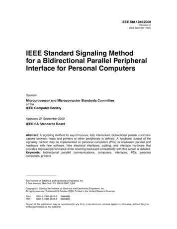
3. Detailed Circuit Description3.1 Processor clock circuitry reset circuitryThe microprocessor is a 6502A and runs at either 1 or 2 MHz. Mostprocessing is done at 2 MHz, including accesses to the RAM and ROM, butthe processor slows down to 1 MHz when addressing slow devices, viz.the 1 MHz extension bus, the ADC, the two VIA's, the 6845 CRTcontroller, the ACIA, and the serial processor. Clock signals for themicroprocessor are produced by a 16 MHz crystal oscillator (IC43) inconjunction with divider circuitry in part of the video processor (IC6)which produces 8, 4, 2 and 1 MHz signals. The 1 MHz signal comingdirectly from the video processor is only used for the Teletextgenerator chip, whilst a D-type flip-flop (half of IC34) divides the 2MHz clock signal in order to produce the system 1 MHz clock (1 MHzE). A2 MHz signal of suitable phase is produced at the output of another Dtype (half of IC31) which remembers when a 1 MHz cycle has beenrequested. At the appropriate time, as governed by the 2 MHz clock, oneof the 2 MHz clock cycles is masked off by the D-type (half of IC34)and when this happens the D-type that remembered that a request hadbeen made, is cleared. Depending on the phase relationship between the1 and 2 MHz clocks at the time of the request, the delay on the 2 MHzEclock is different as illustrated by the diagrams below. The followingsimple program will produce these conditions alternately, so that theymay be viewed with an oscilloscope.1020304050607080P% &3000[ SEI.startSTA &FC00STA &FC00JMP start]CALL &30009
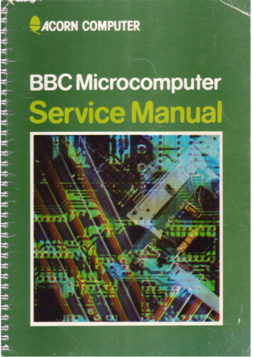
A 555 timer circuit (IC16) provides a reset signal both at power up andalso when the BREAK key is pressed. There is also a separate resetcircuit using a CR combination from the 5 volt power supply (C10 andR20 and D1), to provide a signal called Reset A which is fed to IC3,the internal VIA. The idea is that although the 555 timer produces ageneral reset at power up or when the BREAK key is pressed, Reset Agoes low only on power up. By interrogating the interrupt register onIC3 on the occurrence of a general reset, the microprocessor candiscover Whether it was a "cold start", ie power up, or a "warm start",ie the BREAK key has been pressed when the system has already been inuse for some time.3.2 Memory and address decoding31 1/4 Kbytes of ROM are catered for in the address map. 15 1/4 Kbytesof this ae contained in the operating system (IC51). This is in fact a16K device but 3/4K of it is left unused and it is in this area thatthe I-0 device memory map is situated. Four other ROMs (ICs 52, 88,100 and 101) are on the main circuit board. They may all be 16 Kbytedevices, in which case any one of them may be switched into the 16Kbyte space in the memory map by writing to the ROM select latch (IC76). Alternatively, four 4 Kbyte ROMs may be in these four sockets inorder to fill the 16 Kbyte space assigned. In this case, a two line tofour line decoder (half of IC20) is used to select which of the fourdevices is being addressed by the address lines Al2 and A13. Mixturesof these two cases are allowed for, for instance two pairs of 8 KbyteROMs, one pair or the other being selected by the ROM select latch andthen the ROM to be used in each pair being selected by the 2-4 lineaddress decoder. Address decoding for the ROMs is by IC21 which decodesmemory addresses &8000 to &C000 and &C000 to &FFFF. Locations from 0 &7FFF are assigned to the dynamic RAM, and this is decoded by feedingA15 into pin 4 of IC21. All the rest of the hardware is mapped withinlocations &FC00 to &FEFF. This is decoded by IC22, whilst ICs 20 and 25are used to mask off the ROM over this range of addresses. ICs 24 and26 decode the individual devices within this range, some of which areread or write only. IC23 detects when a slow 1 MHz device is beingaddressed and it calls for the 6502 to execute a slow clock cycle.Note that in early versions of the BBC Microcomputer, the operatingsystem was contained within 4 EPROMs in IC positions 52, 88, 100 and101 while the BASIC interpreter was located in IC51. This arrangementis abnormal and has been phased out. Refer to the link selection survey(5.1) for more detailed information on this.10
11
3.3 CRT controller video processor Teletext hardwareRandom Access Memory on the Microcomputer is provided by either 8 or 16dynamic memory devices (ICs 53-
BBC Microcomputer service manual SECTION 1 BBC Microcomputer Models A and B (ANA01 - ANB04) SECTION 2 BBC Microcomputer Model B (ANB51 - ANB54) . This computer was designed and manufactured to comply with BS 415. In order to ensu