Transcription
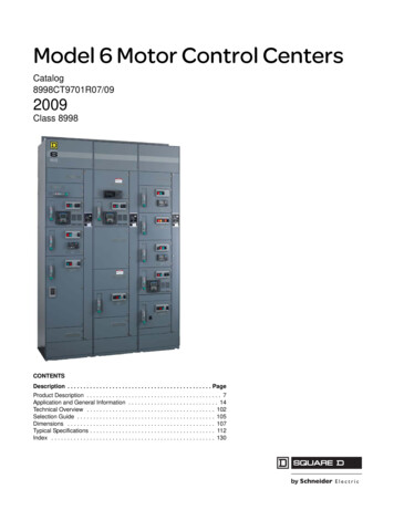
Model 6 Motor Control CentersCatalog8998CT9701R07/092009Class 8998CONTENTSDescription . . . . . . . . . . . . . . . . . . . . . . . . . . . . . . . . . . . . . . . . . . . . . PageProduct Description . . . . . . . . . . . . . . . . . . . . . . . . . . . . . . . . . . . . . . . . . . 7Application and General Information . . . . . . . . . . . . . . . . . . . . . . . . . . . . 14Technical Overview . . . . . . . . . . . . . . . . . . . . . . . . . . . . . . . . . . . . . . . . 102Selection Guide . . . . . . . . . . . . . . . . . . . . . . . . . . . . . . . . . . . . . . . . . . . 105Dimensions . . . . . . . . . . . . . . . . . . . . . . . . . . . . . . . . . . . . . . . . . . . . . . 107Typical Specifications . . . . . . . . . . . . . . . . . . . . . . . . . . . . . . . . . . . . . . . 112Index . . . . . . . . . . . . . . . . . . . . . . . . . . . . . . . . . . . . . . . . . . . . . . . . . . . 130
Model 6 Motor Control CentersTable of ContentsProduct Description. 7Introduction . 7Features . 8Codes and Standards . 9Certification . 9NEMA/EEMAC Wiring Classes and Enclosure Types . 9Wiring Classes . 9Class 1—Independent Units . 9Class 2—Interconnected Units . 9Type A. 9Type B. 9Type B-D. 9Type B-T . 9Type C . 10Enclosure Types . 10Type 1 . 10Type 1A (Gasketed). 10Type 3R . 10Type 12 . 10Shipping Weights . 10Altitude Ratings . 11Motor Control Center Heat Dissipation . 11Structure Steel Gauge Information . 13Application and General Information. 14Structures and Bussing . 14Structure . 14Bussing Options and Modifications . 14Structure Options and Modifications . 15Special Structures . 15Model 6 to Model 5 Transition Section . 16Switchboard to Model 6 Transition Section . 16Bus Duct Connection . 16Model 4 to Model 6 Transition Section . 17Incoming Devices . 18Main Lug Compartments . 18Main Circuit Breakers . 19Optional Masterpact Power Circuit Breaker Main Units—Stored Energy/Drawout Style/Insulated Case . 20MCC Masterpact Main Accessory Groups . 22Tie Breakers . 23Main Fusible Switches . 24Standard Wire Lug Ranges (Mechanical) . 243-Phase, 4-Wire Systems . 26PowerLogic Circuit Monitor . 28PowerLogic Power Meter . 29Transient Voltage Surge Suppressor (TVSS) Units for MCC Incoming Mains . 32Model IMA TVSS (120 kA Surge Rating) . 33Model IMA TVSS (160kA Surge Rating) . 33Model IMA TVSS (240 kA Surge Rating) . 33Additional Options . 33Branch Feeder Units . 34Circuit Breaker Branch Feeder Units . 34Fusible Switch Branch Feeder Units . 35Combination Starter Units . 36Full Voltage Non-Reversing (FVNR) Starters with Circuit Breakers . 36Full Voltage Non-Reversing Vacuum Starters with Circuit Breakers . 37Application-Rated Compac 6 Starters—Full Voltage Non-Reversing with Circuit Breakers . 383 1997–2009 Schneider ElectricAll Rights Reserved07/2009
Model 6 Motor Control CentersTable of ContentsFull Voltage Reversing (FVR) Starters with Circuit Breakers . 39Full Voltage Reversing Vacuum Starters with Circuit Breakers . 39Application-Rated Compac 6 Starters—Full Voltage Reversing with Circuit Breakers . 40Reduced Voltage Autotransformer (RVAT) Starters with Circuit Breakers . 41Reduced Voltage Autotransformer (RVAT) Vacuum Starters with Circuit Breakers . 41Full Voltage 2-Step Part-Winding (FVPW) Starters with Circuit Breakers . 42Full Voltage 2-Speed 1-Winding Starters (Consequent Pole) with Circuit Breakers . 42Full Voltage 2-Speed 2-Winding Starters (Separate Winding) with Circuit Breakers . 43Full Voltage 2-Speed Reversing Starters with Circuit Breakers . 43Wye-Delta Closed Transition Starters with Circuit Breakers (Non-UL Listed) . 44Wye-Delta Open Transition Starters with Circuit Breakers (Non-UL Listed) . 45Full Voltage Non-Reversing (FVNR) Starters with Fusible Switch Disconnects . 46Full Voltage Non-Reversing Vacuum Starters with Fusible Switch Disconnects . 46Application-Rated Compac 6 Starters—Full Voltage Non-Reversing with Fusible Disconnects .47Full Voltage Reversing (FVR) Starters with Fusible Switch Disconnects . 48Full Voltage Reversing Vacuum Starters with Fusible Switch Disconnects . 48Application-Rated Compac 6 Starters—Full Voltage Reversing with Fusible Disconnects .49Reduced Voltage Autotransformer (RVAT) Starters with Fusible Switch Disconnects . 50Reduced Voltage Autotransformer Vacuum Starters with Fusible Switch Disconnects . 50Full Voltage 2-Step Part-Winding (FVPW) Starters with Fusible Switch Disconnects . 50Full Voltage 2-Speed, 1-Winding Starters (Consequent Pole) with Fusible Switch Disconnects .51Full Voltage 2-Speed, 2-Winding Starters (Separate Winding) with Fusible Switch Disconnects .51Full Voltage 2-Speed Reversing Starters with Fusible Switch Disconnects . 51Wye-Delta Closed Transition Starters with Fusible Switch Disconnects (Non-UL Listed) . 52Wye-Delta Open Transition Starters with Fusible Switch Disconnects (Non-UL Listed) . 52Altivar 61 and 71 AC Drives . 53MCC Package Features .53Factory Options: . 53Altivar AC Drive Features . 54Options . 55Combination Altistart 48 Soft Start Units . 60Selection . 60Standard Duty Applications . 60Severe Duty Applications . 60Features . 62Shorting Contactor . 62Torque Control System (TCS) . 62Starting and Stopping . 62Protective Features . 62Monitoring and Indication . 63NEMA/EEMAC Type 3R Enclosure Applications for AC Drives and Soft Starts . 66Environmental Control . 66Ratings . 67Unit Options . 68Options And Modifications . 68Pilot Devices . 71Pilot Lights . 72Overload Relays . 73TeSys T Motor Management Controller . 74Motor Logic Solid-State Overload Relays .75Motor Logic Plus Solid State Overload Relays . 76. 86AccuSine Power Correction SystemGeneral Information . 86Accusine PCS Sizing . 87Single-Phase Distribution Transformers 120/240V Secondary . 88Three-Phase Distribution Transformers 208Y/120 V Secondary . 89407/2009 1997–2009 Schneider ElectricAll Rights Reserved
Model 6 Motor Control CentersTable of ContentsDistribution Panelboards . 90Factory Installed Panelboard Branch Circuit Breakers . 90Empty Mounting Units . 91Full Section Empty Mounting Units (Relay Section) . 91Unwired Master Terminal Compartment . 91Blank Doors . 91Power Factor Correction Capacitors . 92Selection . 92Capacitor Sizing Table—480 V . 93PowerLogic Ethernet Gateways . 94Transparent Ready Equipment Configurations . 94Gateway Ethernet Switches . 94High Resistance Ground Unit . 95ASCO 7000 Series Automatic Transfer Switches With Microprocessor Control Panel(Non-UL Listed) . 96Model 6 iMCCs . 98Common Mounting Configurations for Automation Components . 99iMCC-Network Cabling . 100Ethernet Switches . 100Repeaters/Bridges/Gateways . 101Technical Overview. 102Short Circuit Current Ratings . 102Bus Bracing or Withstand Rating . 102Integrated Equipment Rating . 102Interrupt Rating . 102Series Connected Short Circuit Current Ratings . 102Short Circuit Current Rating . 102UL Listed Short Circuit Current Ratings . 103“Self-Certified” Short Circuit Current Ratings . 103Selection Guide. 105Layout Instructions . 105Unit Designation Chart for Planning . 106Dimensions . 107General . 107NEMA/EEMAC Type 1, Type 1A (Gasketed), or Type 12 Enclosures . 107NEMA/EEMAC Type 3R Non-Walk-In Basic Enclosures . 108Bottom Conduit Entry . 109Top Conduit Entry . 111Typical Specifications . 112Part 1 General . 1121.01 Description . 1121.02 Submittals . 1121.03 Regulatory Requirements . 1121.04 Packing/Shipping . 1121.05 Storage . 1121.06 Warranty . 112Part 2 Product . 1122.01 Manufacturers . 1122.02 Materials . 1132.03 MCC Finish . 1132.04 Structures . 1132.05 Wireways . 1142.06 Barriers . 1142.07 Bussing . 1145 1997–2009 Schneider ElectricAll Rights Reserved07/2009
Model 6 Motor Control CentersTable of Contents2.08 Typical Unit Construction . 1152.09 Components for Typical Units . 1162.10 Six-Inch Unit Construction . 1162.11 Components for Six-Inch Units . 1172.12 Adjustable Frequency AC Drive Unit Construction . 1182.13 Solid-State Reduced-Voltage Starter Unit Construction .1232.14 General Communication Cabling . 1272.15 Modbus Communication Cabling . 1272.16 Ethernet (Modbus TCP) Communication Cabling . 1272.17 DeviceNet Communication Cabling .1272.18 CANopen Communication Cabling . 1282.19 PROFIBUS DP Communication Cabling . 1282.20 Quality Control . 128Part 3 Execution . 1293.01 Location . 129607/2009 1997–2009 Schneider ElectricAll Rights Reserved
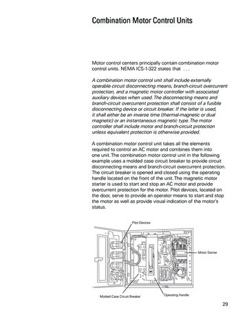
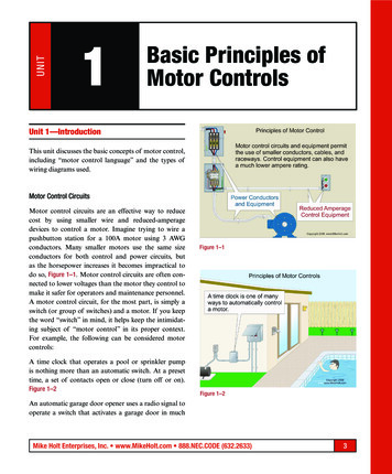
Model 6 Motor Control CentersIntroductionProduct DescriptionProduct DescriptionIntroductionMotor control centers (MCCs) provide the most suitable method for grouping electrical motor control,automation, and power distribution in a compact and economical package. Motor control centers consistof totally enclosed, dead front, free-standing structures bolted together. These sections support andhouse control units, a common bus bar for distributing power to the control units, and a network of wiretrough and conductor entrance areas for accommodating incoming and outgoing load and control wires.The control units consist of components such as combination motor starters, branch feeder devices,AC drives, soft starts, or lighting panelboards. Each unit is mounted in an individual, isolatedcompartment having its own door. Standard MCC dimensions are 20 in. wide (including a 4 in. verticalwireway trough) by 90 in. high (add 1.5 in. base channel and a 3 in. removable top lifting channel) by15 or 20 in. deep. Larger sections are often required for mounting larger equipment or for providingspace for customer-mounted devices.Two package styles are available: standard and industrial. These Model 6 feature packages allow youto custom design the MCC to fit your specific requirements. The standard package lets you tailor theMCC by selecting only those options that you need for an individual project, guaranteeing the optimalcost/value balance. The industrial package includes options most often requested and specified byindustrial customers. Offering the options as part of a package reduces the possibility of leaving outcommon industrial features. See the following table for a comparison of the two packages.OptionStandard PackageIndustrial PackageStructure FeaturesVertical ground bus materialSteelCopperHorizontal bus materialTin-plated aluminum1Tin-plated copperFishtape barriersOptionalIncludedUnit FeaturesInterior colorGrayWhiteNameplatesOptionalIncludedX1 and X2 wired to terminal blocksOptionalIncluded1Exceptions: 1600–2500 A are tin plated copper.All features of the industrial package can be added individually to the standard version.7 1997–2009 Schneider ElectricAll Rights Reserved07/2009
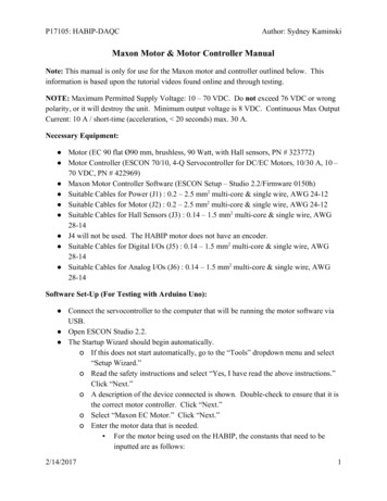
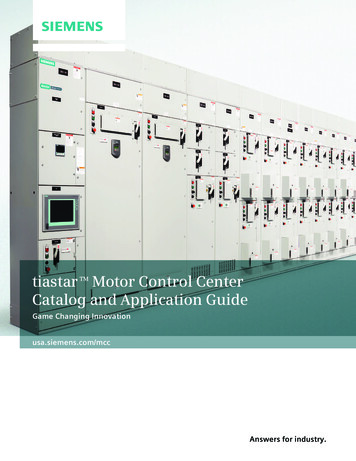
Model 6 Motor Control CentersProduct DescriptionFeaturesFeatures Horizontal power bus is located at the top of the structure for easy installation, inspection, andmaintenance without the need to remove units. Non-conductive, two-piece, sliding, horizontal bus barrier provides convenient access for splicingand maintenance without the need to remove the panels. Captive, four-bolt, horizontal splice bars with self-contained nuts and hardware make installationeasy and reduce the possibility of splice bar loss. A full-depth vertical wireway maximizes the wire pulling area. The Model 6 MCC has the largestvertical wireway in the industry. Vertical bus barriers and wireway openings, when supplied, are built in 3 in. increments. Thisfeature allows more mounting flexibility for the units and reduces wasted space in the enclosure. Vertical ground bus is located in each section. This bus mates with ground stabs on the rear ofeach plug-on unit to create a positive ground connection, with first make/last break operation. Frame is constructed with 12-gauge steel, and features welded corner channels for exceptionalstructural rigidity. Leveling notches in the base channel provide a means of aligning the section during installation. Cast metal handle, an industry-exclusive feature, is more rugged than composites, and clearlyindicates disconnect status, including a ‘tripped’ circuit breaker, for added safety. Quarter-turn fasteners on unit and wireway doors expedite closing and opening. Each unit is fully compartmentalized, with solid side, back, and bottom plates. This feature allowsmore mounting space for components and confines any potential faults within the individual unit. A hinged, or fold-down, unit bottom plate allows additional space for wiring and maintenance.Sliding Bus BarriersFull DepthVertical Wireway(Right-Side View)Structural IntegrityL-shaped unit door hinge pins are easily removed with a screwdriver for general maintenance.InnovativeShrouded Power StabsShrouded power stabs protect stabs against damage during unit maintenance, and provide aself-aligning system for installation of units and connection to the vertical bus.807/2009 1997–2009 Schneider ElectricAll Rights Reserved
Model 6 Motor Control CentersCodes and Standards / NEMA/EEMAC Wiring Classes, Enclosure TypesProduct DescriptionCodes and StandardsModel 6 Motor Control Centers are manufactured to National Electrical Manufacturers Association(NEMA) Standard ICS 18-2001 and Electrical Equipment Manufacturers Association of Canada(EEMAC) standards. Model 6 MCCs are also manufactured to Underwriters Laboratories (UL)Standard 845 and bear the “UL Listed” label, where applicable. The “UL Listed” mark is applied tovertical sections and units that are installed within those sections. It should be noted that sections andinstalled units are independently listed devices. Thus, it is possible to have non-UL Listed unitsinstalled in UL Listed vertical sections. All sections and units listed in this catalog are UL Listed, unless otherwise noted. The Model 6 MCCmeets Canadian Standards Association (CSA) specification standards and can carry the CSA label.CertificationModel 6 Motor Control Centers are certified by the American Bureau of Shipping (ABS) for use inpower distribution, control, and protection of motor and non-motor loads for multiple applications onboard ABS Classed Vessels, Offshore Rigs and Platforms, and Marine applications. ABS developsand verifies conformance with standards for design, construction, and operational mainte
Motor control centers (MCCs) provide the most suitable method for grouping electrical motor control, automation, and power distribution in a compact and economical package. Motor control centers consist of totally enclosed, dead front, free-standing structures bolted together. These sections support and