Transcription
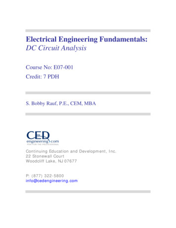
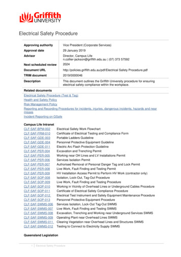
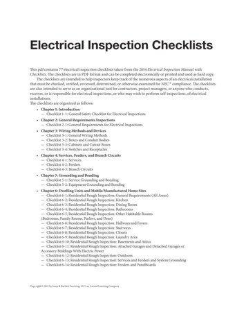
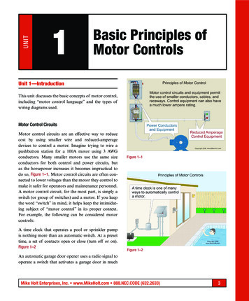
UNIT1Basic Principles ofMotor ControlsUnit 1—IntroductionThis unit discusses the basic concepts of motor control,including “motor control language” and the types ofwiring diagrams used.Motor Control CircuitsMotor control circuits are an effective way to reducecost by using smaller wire and reduced-amperagedevices to control a motor. Imagine trying to wire apushbutton station for a 100A motor using 3 AWGconductors. Many smaller motors use the same sizeconductors for both control and power circuits, butas the horsepower increases it becomes impractical todo so, Figure 1–1. Motor control circuits are often connected to lower voltages than the motor they control tomake it safer for operators and maintenance personnel.A motor control circuit, for the most part, is simply aswitch (or group of switches) and a motor. If you keepthe word “switch” in mind, it helps keep the intimidating subject of “motor control” in its proper context.For example, the following can be considered motorcontrols:A time clock that operates a pool or sprinkler pumpis nothing more than an automatic switch. At a presettime, a set of contacts open or close (turn off or on).Figure 1–2Figure 1–1Figure 1–2An automatic garage door opener uses a radio signal tooperate a switch that activates a garage door in muchMike Holt Enterprises, Inc. www.MikeHolt.com 888.NEC.CODE (632.2633)3
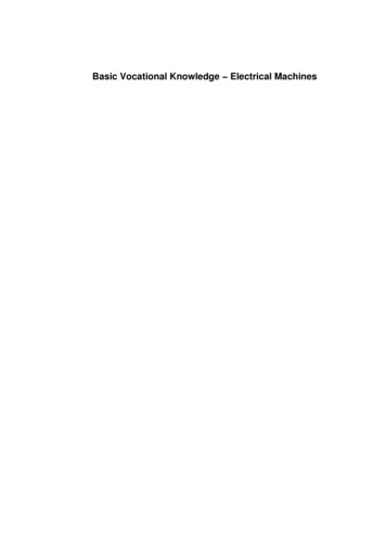
Unit 1Basic Principles of Motor Controlsthe same manner as a typical “up-down” pushbuttonstation.Many motors are controlled by computerized control systems, solid-state logic controls, or programmable logic controllers (PLCs). The fundamentals ofcontrol systems still apply. The PLC controls an external output based on the logic of a control program, andthat output controls the motor or groups of motors byusing a magnetic starter, and in some cases additionalrelays. PLCs and other solid-state control devices wereoriginally invented to provide less expensive replacements for older automated systems that used large numbers of relays and mechanical timers. In some cases, asingle PLC can replace thousands of relays resulting inless expensive wiring systems that offer greater flexibilityin control designs.Author’s Comments:device will operate to open the circuit because of theincreased heat caused by the current running throughit. A magnetic starter or other motor controllers mayinclude overload devices, or they may be an integral partof the motor, particularly with small motors.Author’s Comment: Short circuits and ground faultsaren’t considered overloads.There are two basic designs of motor control equipment, NEMA and IEC.NEMA (National Electrical Manufacturers Association).NEMA is a trade association for manufacturers of electrical equipment and supplies. NEMA standards specify motor horsepower (hp) ratings, speeds, motor framesizes and dimensions, motor torques, motor starter sizeratings, and enclosure specifications. In industrial processes, the control of pressure, flow,speed, temperature, and other items are essential forefficient productivity and safety. Devices such as solidstate sensors, static controls, solid-state relays, andprogrammable controls can provide very precise controlfor an industrial process.NEMA-rated products are typically heavy duty, can beused in a broad range of applications, and some starters can be maintained and repaired. For these reasons,they’re often more expensive than IEC motor starters.NEMA-rated motors and motor controllers are thetype most commonly used in North America. Although the subject of solid-state controls isn’t coveredin detail in this textbook, the concepts are very similar to other motor controls in that they essentially useswitches to control motors.IEC (International Electrotechnical Commission). IECis an international standards organization. IEC motorstarters are often less expensive, smaller in size, are tailored for specific motor performance requirements, andthe selection of the right starter for each application isvery important. IEC-rated motor controllers are widelyused in Europe and Asia. Many experts agree that the best way to learn aboutmotor controls is to start with the standard control methods covered in this textbook. This statement also applieswhen electronic controls are the subject being studied.Many control circuits include motor overload protection devices. Traditional overload (OL) protectors operate on the relationship between heat and current. Ascurrent increases, heat increases. If an overload deviceis rated 10A, and the current exceeds that rating, the OL41.1 Motor Control LanguageElectrical symbols, words, and line diagrams providethe information necessary to understand the operationof motor control circuits. Used together, they create aMike Holt’s Illustrated Guide to Understanding Basic Motor Controls
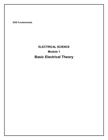
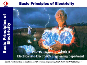
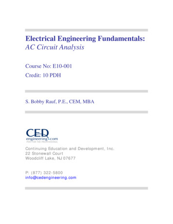
Basic Principles of Motor Controlstype of motor control “language” that’s used to transfer information and ideas quickly and efficiently.The symbols in motor control schematics representdevices, power conductors, control conductors, conductor connections and terminals, and sometimes themotor itself.The words, phrases, and abbreviations in a schematicare generally accepted terms that represent functions,describe actions, and list sequences of operation.In many cases, the symbols and words have a similarityto the items they represent. The basic types of schematics are shown in Figure 1–3. Parts A, B, and C of thatfigure illustrate three different methods of representingthe same control circuit.Unit 1(1) Ladder Diagrams (Figure 1–4)Ladder diagrams are also called “line diagrams” or“elementary diagrams.” They’re used to representthe function of the control circuit and the associateddevices, but don’t show the components of the control circuit in their actual positions. As control circuits become more complex, a ladder diagram canbe less complicated to read than a wiring or connection diagram. For example, in Figure 1‑4, notice theset of contacts marked M under the start pushbutton.The M contacts marked 2 and 3 are actually locatedin the motor starter fairly close to the coil, as shownin Figure 1–3B, and the normal physical appearanceof these contacts often look as shown in Figure 1–3C.(Notice that all three examples of the M contacts areshown with a blue background in Figure 1–3.)Figure 1–4Figure 1–3The ladder diagrams in Figures 1–4 and 1–5 illustrateselectrical function, showing the M contacts in parallel with the start pushbutton to form what’s called a“holding circuit.” The physical location of the M contacts isn’t shown in the ladder diagram.Mike Holt Enterprises, Inc. www.MikeHolt.com 888.NEC.CODE (632.2633)5
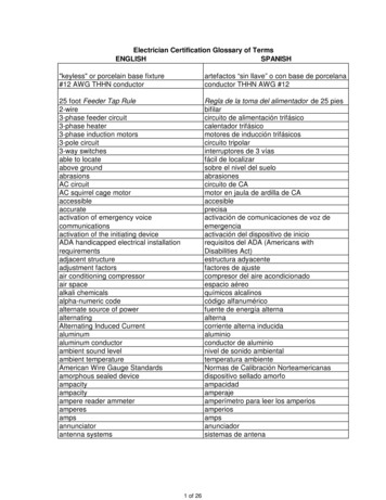
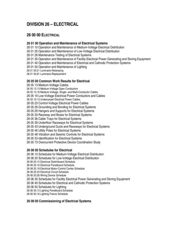
Unit 1Basic Principles of Motor ControlsFigure 1–5Figure 1–6Figure 1–5 shows a more complicated version of aladder diagram. Notice that the horizontal lines in thiscontrol circuit are similar to the rungs of a ladder.Author’s Comment: An important point to remember isthat schematics show motors and control equipment in theresting, or off state (sometimes called the “shelf” state).Part of the difficulty, when first learning about motor controls, is in understanding how the different components ofthe control circuit interrelate during the operation of thecontrols.(2) Connection Diagrams (Figure 1–6)Author’s Comments:Connection diagrams, or wiring diagrams, show thecomponents of the control circuit in a semblance oftheir actual physical locations. The start-stop pushbutton station is shown more as an actual device in thecontrol circuit wired to a set of contacts marked 2 and3. In Figure 1–4, the wires on each side of the M contacts trace back to points 2 and 3 on either side of thestart pushbutton. The contacts marked M in Figure 1–4are the same contacts as those marked 2 and 3 inFigure 1–6.6Different manufacturers of control devices, as well asbooks about motor controls, use different methodsof showing the control circuit wiring. For example, inFigure 1–3B1, the control wiring from the start-stoppushbutton station runs to the actual connection points1, 2, and 3. As the wiring diagrams become more complicated, the optional method shown in Figure 1–3B2is frequently used to show the connection points forthe start-stop pushbutton station. Here, in Figure 1–6,instead of running the control wires to the actual connection point, arrowed lines represent connections to bemade by the installer. M any times you see plain lines (no arrows) with numbers to indicate connections to be made by the installer.We use both methods in this textbook. Many of the components and symbols used in ladderdiagrams and wiring diagrams are the same. In orderto make schematics easier to read, some manufacturers combine the two types of diagrams together. Someequipment comes with both ladder diagrams and wiringdiagrams.Mike Holt’s Illustrated Guide to Understanding Basic Motor Controls
Basic Principles of Motor ControlsUnit 1 Remember, ladder diagrams show electrical functionand wiring diagrams show the actual components.It’s very common to find different styles of schematicscombined in a single wiring diagram. The top part ofthe diagram in Figure 1–7 is in the style of a connectiondiagram, while the style showing the start-stop stationand coil is similar to a ladder diagram.Figure 1–8Author’s Comments:Figure 1–7(3) Pictorial Diagrams (Figure 1–8)Pictorial diagrams are often used in educational material and as exploded views or cut-away views in installation and maintenance literature. Pictorial diagramshelp students see actual devices and components usedin motor control circuits and how they relate to thesymbols used in ladder diagrams and wiring diagrams.For example, the start pushbutton we mentioned earlierhas wires run to the device that contains the set of contacts M in Figure 1–4, and to contact points 2 and 3 inFigure 1–6. O ften a hand-drawn diagram of a control circuit constructed in the field helps in understanding how a circuitfunctions and how to make the necessary connections,especially during the learning process. Figure 1–9shows the hand-drawn version of the 3-wire start-stopcontrol circuit shown in Figure 1–3. Notice that the stoppushbutton is in series with coil M, and that the startpushbutton is in parallel with M contacts 2–3. The entirecontrol circuit in this example is in parallel between line1 and line 2. These basic relationships can be found inmany control circuits. T he numbers in this diagram are simply for the aid ofthe reader and it don’t imply that terminal 1 on onedevice should always be connected to terminal 1 onanother device.Once you understand the terminology and symbolsinvolved in motor control circuit wiring, understandinghow it works becomes easier and less intimidating.Mike Holt Enterprises, Inc. www.MikeHolt.com 888.NEC.CODE (632.2633)7
Unit 1Basic Principles of Motor ControlsWhen beginning this study of basic motor controls,remember that motor controls are basically different kinds of switches that turn things on and off, bothmanually and automatically. This may help you keepthings in perspective.There are many good books available for moreadvanced studies about this subject. Also check withthe manufacturers of motor control equipment for educational material and standard motor control circuits.Unit 1—ConclusionFigure 1–91.2 Motor Control BasicsThe purpose of this textbook is to introduce the basicsof motor controls. Many of the control circuits that arecovered are standard control circuits used in many different applications. Each circuit can have several variationsand optional devices in addition to those included in theschematics. This textbook won’t teach you all of thesecontrol circuit variations, but will give you a basic understanding of motor controls, and how to read wiring diagrams and understand the sequences of operation.8This unit explained the basic concepts of motor controls, concentrating on how specialized electrical symbols, words, and line diagrams are used to conveyinformation about motor control circuits. It providedan introduction to the following types of diagrams,which are used extensively throughout this textbook: Ladder diagrams (these are also called “linediagrams” or “elementary diagrams”). Connection diagrams (also called “wiringdiagrams”). Pictorial diagrams.Mike Holt’s Illustrated Guide to Understanding Basic Motor Controls
UNITPractice Questions1Practice QuestionsUnit 1—Practice Questions5.Introduction1.A motor control circuit, for the most part, issimply a and a motor.(a) motor(b) switch(c) feeder(d) magnet2.6.4.7.(a) line diagrams(b) elementary diagrams(c) pictorial diagrams(d) a or bare used mostly in educational material andas exploded views or cut-away views in installationand maintenance literature.(a) Ladder diagrams(b) Connection diagrams(c) Wiring diagrams(d) Pictorial diagramsSchematics show motors and control equipmentin their “resting” or “shelf ” state.Ladder diagrams are also known as .Connection diagrams are also called wiringdiagrams.(a) True(b) False1.1 Motor Control Language(a) True(b) Falseare used to represent the function of thecontrol circuit and the associated devices, butdon’t show the components of the control circuitin their actual positions.(a) Ladder diagrams(b) Connection diagrams(c) Wiring diagrams(d) Pictorial diagramsMany types of overload protectors operate on therelationship between .(a) heat and current(b) the neutral conductor and the earth(c) branch circuits and feeders(d) voltage and wattage3.Unit 18.The motor control circuit shown in Figure 1–10 is a.(a) ladder diagram(b) connection diagram(c) wiring diagram(d) pictorial diagramMike Holt Enterprises, Inc. www.MikeHolt.com 888.NEC.CODE (632.2633)9
Unit 1Practice Questions9. The motor control circuit shown in Figure 1–11 is a.(a) ladder diagram(b) connection diagram(c) wiring diagram(d) pictorial diagramFigure 1–10Figure 1–1110Mike Holt’s Illustrated Guide to Understanding Basic Motor Controls
UNIT 1 Basic Principles of Motor Controls Unit 1—Introduction This unit discusses the basic concepts of motor control, including “motor control language” and the types of wiring diagrams used. Motor Control Circuits Motor control circuits are an effective way