Transcription
Concurrent Geometric, Structural and EnvironmentalDesign: Louvre Abu DhabiFrédéric Imbert, Kathryn Stutts FrostAteliers Jean Nouvel / HW ArchitectureAl FisherBuro Happold SMART SolutionsAndrew WittGehry TechnologiesVincent TourreLUNAM, Ecole Centrale de Nantes, CERMA UMR CNRS 1563Benjamin KorenOne to One Computational GeometryAbstract. Sophisticated contemporary design projects are constrained by themulti-objective requirements of architects, engineers, and specialty consultants.The Louvre Abu Dhabi represents a step forward in the concurrent engineering ofmulti-objective geometry conditions for environmentally informed envelope design.The project takes advantage of associative and generative modeling technology tocreate a framework for multi-constraint problems in which all stakeholders canembed their own requirements and design rules in a real-time and collaborativeway. At the same time, the creation of a globally shared, web-hosted, versionedmodel provides a dramatically more open and transparent way for designers andengineers to converge toward a shared solution for the geometric andenvironmental challenges. Thus the Louvre Abu Dhabi provides a case study for anew concurrent design approach to multi-constraint geometric problems inarchitecture.
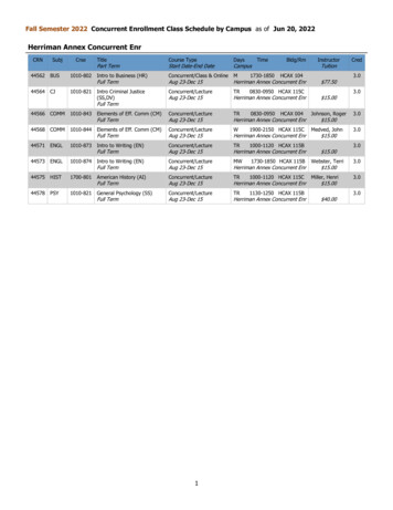
1IntroductionEvery building is naturally subject to the demands and desires of manyconstituents, each of which hopes to achieve certain objectives with a project. Tosatisfy these multiple and often divergent objectives, building design has becomean increasingly collaborative activity, often drawing on the knowledge of dozensor hundreds of experts to achieve a successful result. Today the historical designteam of architect, structural engineer, and mechanical engineer may be joined by amyriad of new consultants for facade, maintenance, museography, accessibility,sustainability, and more. The staggering range of rules, constraints, andrequirements brought to bear on a project by these consultants often has directimpact on building geometry. New technologies, particularly parametric tools andconcurrent design platforms, provide a means to synthetically optimize designs forthese various geometric objectives.A paradigmatic project to illustrate this multi-objective approach to geometry isthe design of the Louvre Abu Dhabi (LAD). The Louvre Abu Dhabi is a newclassical arts museum in the United Arab Emirates planned as a central feature ofthe cultural district of Saadiyat Island. Consisting of 22,500m² of gallery space andsupporting programs, the museum buildings are arranged in a micro-city floatingon the sea, shaded by an iconic shallow dome (Figure 1).At the heart of the design concept, this giant dome structure performsenvironmental, aesthetic, and structural functions. Environmentally, it providesshade and cooler temperatures to the outdoor public spaces connecting the multiplebuildings of the museum village. Aesthetically, it functions as an external open-aircanopy, filtering the natural light of the sun and creating a dramatic and constantlytransforming lighting effect beneath the dome. Architect Jean Nouvel stated:“This micro-city requires a micro-climate that would give the visitor a feeling ofentering a different world. The building is covered with a large dome, a formcommon to all civilizations. This one is made of a web of different patternsinterlaced into a translucent ceiling which lets a diffuse, magical light comethrough in the best tradition of great Arabian architecture.”Figure 1: Site plan and perspective view beneath the dome.
Concurrent Geometric, Structural and Environmental Design: Louvre Abu DhabiTo achieve this effect, the dome is conceived as a layered series of geometricpatterns, superimposed in a manner that appears haptic although it is highlycontrolled. The role of the interdisciplinary design team was to bring to reality thisvision, taking into account a series of constraints:Aesthetic. The pattern of the floating, filigree canopy is intended to be, ineffect, a marvellously dynamic installation, equal parts mystery and precision.Natural lighting. Below the canopy, the design vision calls for a “rain of light:”visible rays of light and dynamic light patterns on the plaza and walls. Thisdemands the careful control of perforation levels and diffuse light.Environmental. To achieve a comfortable microclimate beneath the dome, acumulative target level of only 1.8% light transmission must be achieved, and alow emissivity material is required for the interior surface.Museography. Natural lighting of the galleries is achieved with variable,specifically prescribed levels of perforation in the dome.Structural. The dome spans 165 meters between only 4 supports, generatinglarge cantilevers. Individual pattern elements span up to 5 meters.Fabrication, Assembly and Maintenance. The brief required a design forbuildability, accessibility and durability over a 100 year lifetime. As much aspossible of the fabrication planning needed to be automated in order for theproject to be feasible.Ultimately, these constraints were translated into specific geometric rules for thedesign. To achieve these disparate and sometimes competing requirements, theteam used advanced parametric tools and concurrent design systems to findoptimal solutions to shared challenges.2An Iterative Integration ProcessThe process of concurrent design for LAD leveraged the flexible collaboration ofmultiple disciplines. The principal design team consisted of the architects, AteliersJean Nouvel (AJN) in association with HW Architecture, and the engineers, BuroHappold (BH) in association with TransSolar. Multiple sub-contractors weredeployed, including Gehry Technologies who provided expertise, software, andinfrastructure for the parametric control of the dome, CERMA research laboratoryfor advanced lighting analysis, and One to One GmbH to manage the productionof the large scale model for design verification. At each level performancerequirements were translated into geometric rules embedded in the core parametricmodel.
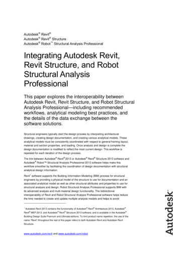
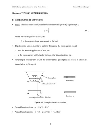
F. Imbert, K. Stutts, A. Fisher, A. Witt, V. Tourre and B. Koren2.1Geometric originsA base geometric pattern to create the filigree web of the canopy was fundamentalto all later design and analysis decisions. This pattern consists of an isoscelestriangle repeated and rotated to form a system of squares and hexagons (Figure 2).The pattern is mapped to the dome surface following an underlying “great circle”grid, resulting in a tessellation that is true at the apex, whilst it distorts nonlinearlytowards the perimeter. The same pattern would later be repeated, rotated, andscaled to achieve the density and intricacy of the final design.Figure 2: Base pattern applied to dome, with studies of derived patterns.2.2Structural iterationsEarly in the design process there were investigations into the potential structure ofthe dome, including concrete, tensegrity, and steel. With steel selected, anextensive period of workshops and design iterations were undertaken,experimenting with different structural typologies, evolving the structure awayfrom a rectilinear arrangement. Ultimately, the geometric base pattern of the domeand the primary structural grid were fused, creating a structural space-frame thatitself acts as one of the many shading layers of the dome. One important effect ofthis deep structural system is that two skins are created, inner and outer surfacesapproximately 6 meters apart, thereby creating a more dynamic light effect underthe dome due to the phenomenon of parallax (Figure 3).Figure 3: Partial digital model illustrating structure and cladding relationship.
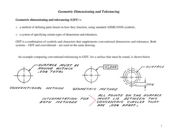
Concurrent Geometric, Structural and Environmental Design: Louvre Abu DhabiIn order to meet these specific, complex engineering and architecturalrequirements, a process of research and development further extended the team’sexisting structural optimisation capabilities. Building on Buro Happold’s SMARTSizer technologies, a novel iterative approach to structural optimisation wasdeveloped for the project enabling a fine balance of a number of interrelatedconstraints: structure self-weight, aesthetics, cost and buildability. Details of thesetechniques can be found in [Shrubshall and Fisher 2011]. Thus exploiting thisapproach enabled an efficient, elegant solution which equally meets all the multiobjective design criteria.Figure 4: An initial deflection optimisation controls the stiffness distribution in the dome,enabling the designer to closely sculpt the global behaviour of structure, before thencontinuing to satisfy all the specific local stress criteria. In utilising this approach, stiffregions within the dome naturally emerge arching between the supports.2.3Cladding iterationsWith the fundamental base pattern established, a set of parameters controlled itstransformation into the ten distinct, superimposed layers of the dome cladding. Thekey relationships to manage were relative scale, rotation and translation of thepattern components. A series of trials ultimately resulted in a combination ofparameters which provide variation and perceived intricacy whilst still maintainingconsistent, predictable points of connection between layers and sufficient densityfor microclimate effects.Each cladding layer has not only a distinct pattern scale and orientation relativeto the others, but also mass-customized member widths in order to achieve thenecessary apertures for daylighting across the dome surface. By varying thesewidths within an established range, the dome achieves areas of greater and lesserperforation (Figure 5). These perforation levels were calculated and ultimatelycontrolled using a process of inverse lighting analysis.
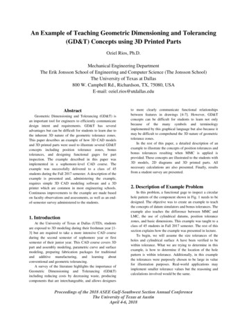
F. Imbert, K. Stutts, A. Fisher, A. Witt, V. Tourre and B. KorenFigure 5: The five outer layers of cladding of various scales, rotations, and member widths.2.4Inverse lightingCERMA, an architectural and urban ambient environment laboratory, undertookthe challenge of computing the perforation variations on the dome, taking intoaccount the natural lighting intentions given by the architects. As the perforationsof the dome are small compared to the dome size, the perforation ratio over thedome can be seen as a transparency map. In a performative design approach[Kolarevic and Malkawi 2005], the inverse lighting paradigm applied to thearchitectural design is used in order to produce this transparency map. Severalsteps ensured the precision and fidelity of this inverse lighting model.The inverse natural lighting model. Several methods allow the inversion oflighting simulations in architecture [Patow and Pueyo 2005]. In the case of LouvreAbu Dhabi, the dome is a light filter which can be seen as a set of intermediarylight sources. These intermediary light sources have an anisotropic feature whichis essential in the solving of the inverse problem. The emittance property of theseintermediary light sources is bound to the transparency properties of the filter.Therefore the inverse problem can be seen as an emittance research of anisotropiclight sources. The integration of this approach into the collaborative design processis achieved through the use of a light-based parametric design tool: EEL, which isdeveloped to handle such complex features as a heterogeneous light distribution.The detailed case study can be found in [Tourre and Miguet 2010].Computing the transparency map. The process of the inverse lighting study can besummarized as follows: Preliminary lighting simulations on the 3D model, in order to aid thedescription of lighting intentions Definition of the lighting intention map Inverse natural lighting with the EEL prototype Computing the transparency map Verifying the dome configuration with a forward lighting approachThe definition of the lighting intention map is essential to the inverse lightingprocess. This intention map shows explicitly where designers hope to achievevarious light and temperature levels. In the case of the Louvre Abu Dhabi, thelighting intention map developed by the architects contains three areas: plaza,galleries having roof lights, and other buildings and water (Figure 6). The intendedilluminance levels (in lux) were based on a report by the microclimate specialists
Concurrent Geometric, Structural and Environmental Design: Louvre Abu DhabiTransSolar, preliminary lighting studies, and meetings between AJN, BH, andCERMA. These intention maps are very complex because they must cover therange over the course of a year.Figure 6: Lighting intention map used as input data for the inverse lighting model.The resulting perforation ratio, interpreted from the computed transparencymap, ranges from 2% to 8% over the “natural lighting” areas (galleries), and from0.1% to 1% over the protected areas (plaza, water surface, and other buildings).Therefore, the inverse lighting model responds to this design problem by analysingthe lighting intentions and applying the results to compute the member widths ofthe cladding. The transparency map then becomes the basis for the data-drivenapproach to the parametric variation of the dome.3Parametric Model3.1Computational infrastructureWith these simultaneous design processes under way, it became apparent that theproject would benefit from a shared parametric model for design optimization andfabrication automation. Using Digital Project software and SVN, a web-basedmodel repository, Gehry Technologies put in place an infrastructure that allowedthe concurrent collaboration on the LAD Dome model between the architect,engineer, and consultants. This allowed architects and engineers to worksimultaneously with the same model on different problems, while each adhered toproject-critical constraints that had been agreed upon by the team. The samesystem provided a natural way to distribute content, facilitating studies,collaboration, and training.
F. Imbert, K. Stutts, A. Fisher, A. Witt, V. Tourre and B. KorenFigure 7: Diagram of parametric workflow, detailing how various constraints of the projectwere folded into the central parametric model of the dome.3.2Parametric processThe Digital Project model served as a base for continuing development of thestructure, cladding, lighting, and details of the dome. All of the key constraints ofthese various disciplines were embedded in this concurrent web-distributed model.The structural model took advantage of the semantic architectural objects inDigital Project to generate key analysis wireframe and metadata. The structuralteam continued to use Ansys and Robot for their analysis, but the Digital Projectmodel held the wireframe base that was shared amongst the team. The parametricsystem allowed easy control and testing of variables in the cladding layers, whichwere first instantiated as wireframe centrelines and eventually linked to the inverselighting map to drive member thickness and achieve the desired level ofperforation. In this way, the central model became a responsive data-driven toolfor synthesizing both external light information and structural analysis metrics.The model adapted itself to each data set, providing reciprocal feedback for theinterrelationship between the two.3.3Mathematical opacity controlA major design challenge was to link the geometry to the precise environmentalrequirements, realizing true performance-based design. With the centralizedparametric model established, this was achieved by integrating the specific lightingsimulation data with the geometry generation.An approach was developed by which the required overall opacity of the domeis decomposed into individual translucency maps for each separate layer of
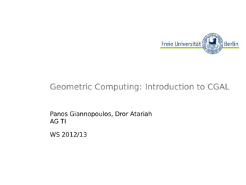
Concurrent Geometric, Structural and Environmental Design: Louvre Abu Dhabicladding. Ratios specified the extent to which each cladding layer contributes tothe whole opacity of the roof. Thus the parametric model is driven by a series ofdistribution functions weighting the dome solidity between the top and bottomskins and then between each sub-layer. For instance the translucency of layer i, tiis:where cT is global translucency at a point on the dome, ts is translucency of thestructure, ρi is translucency ratio of layer i.Starting from the initial physical simulation (as conducted by the inverselighting studies and described above), the translucency decomposition formulaswere integrated into the parametric dome geometry, to calculate opacity values foreach of the layers of the dome. These layer-wise translucency values are defined inzones across the surface enabling the local variation within each layer to bedescribed (Figure 8). Each member of every layer detects its proximity to theclosest analysis zone, and by taking on the assigned thickness within a givenrange, the layer achieves the necessary level of perforation (Figure 9).Figure 8: Overall translucency map with resulting shadow effect beneath the dome.Figure 9: Two examples of the translucency map applied to cladding layers.
F. Imbert, K. Stutts, A. Fisher, A. Witt, V. Tourre and B. Koren3.4Detail studiesAs the design developed, the challenges of detailing the metal cladding membersand connections across the entire dome (approx. 12,000 preassembled modules)were also addressed collaboratively with the parametric model. The constructiondocuments for the dome were fully automated from these detail studies, producingover 300 pages of detail drawings and 3000 pages of numeric quantities for thetendering of the dome. These quantities included not only lengths and widths ofmembers but also vertex-wise angle defects, which helped to generate accurate endcuts for each irregular shape while inducing the proper curvature for the globaldome.Octagon, triangle and square families. Ultimately, the method of assigningmember widths drove the cladding construction details. Geometric families ofcongruent parts were developed to smooth the transitions between individualelements of varying widths. The result was a central single or double rail thatcould also be used as a joint for fixation. Member widths are controlledindependently on either side of the rail, making it possible for asymmetriccombinations to result. Also with this system, a subtle change in memberorientation had to take place. Rather than each linear element being orientednormal to the surface of the sphere, each orientation had to be defined by newplanes established within each octagon, triangle and square family (Figure 10).The slight surface angle that results is variable, but the differences are smallenough to be considered constant for fabrication. The folds also contribute to thevisual nuance of the surface when reflected by the light.Figure 10: Cladding member width catalogue. Families of extrusions provide a semistandardized method of adaptively accommodating a range of member widths.
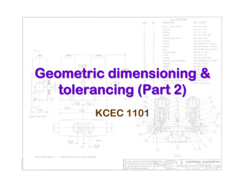
Concurrent Geometric, Structural and Environmental Design: Louvre Abu DhabiFigure 11: Construction documents produced from parametric model: Sorting memberwidths over a single layer (left) & detail showing octagon, triangle, square families (right).4ResultsAt each step, physical simulations were used to supplement and validate the digitalmodels, as in the shadow rendering in figure 8. In addition, a series ofprogressively more detailed prototypes were constructed, including a partial 1:1scale mock up on the site and a 1:33 scale prototype of the entire dome.4.1Large scale prototypeThe fabrication of a 1:33 model, built primarily for light-testing purposes, servedalso as a precursor to the forthcoming full-scale dome erection, as many of theissues relevant in construction had to be addressed for the first time. The modelwas far outside the realm of traditional architectural model-making due to its largedimensions, inherent geometric complexity, precise material specifications andconvoluted assembly logistics (measuring 5.50m in diameter and beingconstructed out of 15280 aluminum and stainless steel parts in less than 6 months).The task of the model’s construction, as well as the concurrent design processleading up to that point, necessitated the engagement of an interdisciplinarycollective. Three cooperating firms were appointed, combining the expertise ofcomputational geometry, state-of-the-art manufacturing and assembly facilitiesand traditional model-making skills, respectively.Primary Structure. Initially, basic structural analysis specifically for the 1:33model was carried out in order to evaluate construction alternatives. The chosenapproach was an all metal structure consisting of non-standard stainless-steelnodes, laser-cut out of flat metal sheets, and lathe-manufactured aluminum bars. A
F. Imbert, K. Stutts, A. Fisher, A. Witt, V. Tourre and B. Korenparametric plug-in for Rhinoceros was developed which enabled the generation ofthe entire primary structure, taking the Digital Project wireframe data as input. Anintegrated optimization algorithm that reduced 2,497 unique members for eachquarter of the dome to 44 standard bar types by varying the length of nodes’ armswithin a range of 12mm - visually almost imperceptible and structurally irrelevant.Each node is unique, 1,079 different types for each quarter, and was automaticallyflattened, labelled and nested. All relevant information for assembly was engravedon each individual connection: the node’s number, the neighbouring node numbersand the bar types to be attached.Figure 12: Components of 1:33 scale dome prototypeCladding Layers. The 1:33 model had to withstand a temperature difference ofapproximately 70 K. Due to the thermal expansion of the structure the only viablesolution for the dome cladding was to apply the same material, Aluminum(AlMg3, H111). The cladding was produced in small modules of approximately600x600mm, assembled with a gap of 0,8mm between each to allow for heatexpansion. For reasons of time and cost, three of the five layers of the interior andouter cladding were merged into one. The layers of each module were individuallypressed into double-curved spherical segments, the pattern of the cladding waterjet-cut, and the layers glued together to form a complete module, which was thenscrewed onto spacers attached to the primary structure.For the large scale prototype, as with the full scale dome, the process of furtherrationalizing the geometry was a crucial step in the development of an efficient,practical and viable solution for its construction.
Concurrent Geometric, Structural and Environmental Design: Louvre Abu DhabiFigure 13: Prototype in progress.4.2Full scale mock-upA full scale portion of the dome was constructed on site beginning the summer of2009. Temporary wooden cladding permitted light testing and validation to becarried out and the results incorporated early into the parametric model. The spacearound the mock up was fully enclosed to block out light from the sides, and thestructure was equipped with a moving platform to simulate the conditions at thecentre of the dome (30 meters above the plaza) as well as the edge (9.5 metersabove). In early 2010 the temporary cladding was replaced with multi-layercladding prototypes, testing the finishes, joints, connections, and fabricationprocedures. As an on-going point of reference during the design period, the mockup served as a valuable tool for concurrent design.Figure 14: Photos of full scale mock-up. This full scale section of the dome could pivot tosimulate any lighting condition on the dome. Photo credits: Neil Francis (left) and StefanZopp (right)
F. Imbert, K. Stutts, A. Fisher, A. Witt, V. Tourre and B. Koren4.3Looking forward: convergent designThus far, the twofold optimisation process to define the dome geometry for bothstructural and environmental performance illustrates how seemingly complexgeometry can be achieved, and in fact emerges naturally, from the interaction andconcurrent design of specific engineering requirements. Integrating into this designprocess the standardisation and fabrication constraints means that a complexarchitectural aesthetic can be realised whilst meeting practical engineeringlimitations.The Louvre Abu Dhabi is now entering construction the phase and preparingfor fabrication and assembly of the dome. Given the complexity of the geometry,the scale of the dome, and the number of parts, a rigorous system for cataloguing,fabrication, and installation is essential. The wealth of information contained in theshared parametric model will be a critical resource as the project becomes areality.Ultimately, the Louvre Abu Dhabi represents a step forward in the reciprocalintegration of environmental, structural, and architectural geometry constraints.The dome is a step beyond even concurrent design to convergent design - iterativeoptimization of multiple constraints toward a synthetic objective. It illustrates therich intersection of collaboration and geometry, and the profound evolutiontowards simultaneous variation and control that is possible with new parametricand concurrent design systems. As the case of the dome shows, the competing,multi-objective constraints of complex projects can be resolved holistically,elevating the capacity of multidisciplinary teams and the quality of unprecedentedprojects.ReferencesKOLAREVIC, B. AND MALKAWI, A.M. (eds), 2005. Performative Architecture:Beyond Instrumentality, Spon Press, New York.KOREN, B.S. 2010. Louvre Abu Dhabi 1/33 – Fabrication of a large-scale physicallight-test model, Ceccato, Hesselgren, Pauly, Pottmann, Wallner (eds)Advances in Architectural Geometry 2010, Springer, 163–174.PATOW, G. AND PUEYO, X. 2005. A Survey of Inverse Surface Design From LightTransport Behavior Specification, Computer Graphics Forum, 24(4): 773–789.SHRUBSHALL, C., FISHER, A., 2011. The Practical Application of StructuralOptimisation in the Design of the Louvre Abu Dhabi. In: Proceedings of theInternational Association for Shell and Spatial Structures Symposium. London.TOURRE, V. AND MIGUET, F. 2010. Lighting intention materialization with a lightbased parametric design model, International Journal of ArchitecturalComputing (IJAC), 8(4): 507–524.
the design of the Louvre Abu Dhabi (LAD). The Louvre Abu Dhabi is a new classical arts museum in the United Arab Emirates planned as a central feature of the cultural district of Saadiyat Island. Consisting of 22,500m² of gallery space and supporting programs, the museum buildings are arranged in a micro-city floating