Transcription
This article has been accepted for inclusion in a future issue of this journal. Content is final as presented, with the exception of pagination.JOURNAL OF MICROELECTROMECHANICAL SYSTEMS1A Microdischarge-Based MonolithicPressure SensorChristine Kay Eun, Xin Luo, Jun-Chieh Wang, Zhongmin Xiong, Mark Kushner, andYogesh Gianchandani, Fellow, IEEEAbstract— This paper describes the investigation of amicrodischarge-based approach for sensing the diaphragm deflection in a monolithically fabricated pressure sensor. This transduction approach is appealing from the viewpoint of miniaturization.The device consists of a deflecting Si diaphragm with a sensingcathode, and a glass substrate with an anode and a reference cathode. The total exterior volume of the device is 0.05 mm3 ; typicalelectrode size and separations are 35 and 10 µm. Pulsed microdischarges are initiated in a sealed chamber formed between Si andglass chips, and are filled with Ar gas. External pressure deflectsthe Si diaphragm and changes the interelectrode spacing, therebyredistributing the current between the anode and two competingcathodes. The differential current is indicative of the diaphragmdeflection which is determined by the external pressure. A 6-maskmicrofabrication process is investigated for device fabrication.Electrode connections to the interior of the chamber are providedby laser drilling and copper electroplating through high aspectratio glass vias. The Si and glass substrates are bonded by Au-Ineutectic. The redistribution of plasma current between competingcathodes, as a consequence of diaphragm deflection over a rangeof pressure, was experimentally demonstrated. First principlesmodeling of transient microdischarges have provided insightsto the fundamental processes responsible for the differentialcurrent and guidance for scaling the device to smallerdimension.[2013-0200]Index Terms— Through-glass vias (TGVs), electroplating,eutectic bonding, plasma modeling.I. I NTRODUCTIONAVARIETY of microscale pressure sensing solutions havebeen explored in the past five decades, of which theManuscript received June 21, 2013; revised February 6, 2014; acceptedMarch 6, 2014. This work was supported by the Advanced Energy Consortium(AEC). Subject Editor A. Seshia.C. K. Eun is with the Center for Wireless Integrated MicroSensing andSystems, University of Michigan, Ann Arbor, MI 48109 USA; and also withthe Department of Electrical Engineering and Computer Science, Universityof Michigan, Ann Arbor, MI 48109 USA (e-mail: eunc@umich.edu).X. Luo is with the Center for Wireless Integrated MicroSensing andSystems, University of Michigan, Ann Arbor, MI 48109 USA; and alsowith the Department of Mechanical Engineering, University of Michigan,Ann Arbor, MI 48109 USA (e-mail: xinluo@umich.edu).J.-C. Wang, Z. Xiong, and M. Kushner are with the Department ofElectrical Engineering and Computer Science, University of Michigan,AnnArbor,MI48109USA (e-mail:junchwan@umich.edu;zxiong@umich.edu; mjkush@umich.edu).Y. Gianchandani is with the Center for Wireless Integrated MicroSensingand Systems, University of Michigan, Ann Arbor, MI 48109 USA; theDepartment of Electrical Engineering and Computer Science, University ofMichigan, Ann Arbor, MI 48109 USA; and also with the Department ofMechanical Engineering, University of Michigan, Ann Arbor, MI 48109 USA(e-mail: yogesh@umich.edu).Color versions of one or more of the figures in this paper are availableonline at http://ieeexplore.ieee.org.Digital Object Identifier 10.1109/JMEMS.2014.2312174most commonly used are piezoresistive and capacitive pressuresensors [1]. Piezoresistive sensors typically measure stressin a diaphragm as it deflects in response to pressure. Incontrast, capacitive pressure sensors respond to diaphragmdeflection rather than stress. The smallest micromachinedpressure sensors that have been reported – e.g., for use withincardiac catheters – use these transduction techniques [1]. Forboth types of sensors, the side-dimensions of the diaphragmsof the smallest devices have been about 1 mm long. Furtherreduction in size has been a challenge for both approaches,but for different reasons.For piezoresistive pressure sensors, reducing the diaphragmdiameter presents a challenge in localizing the resistor. If theresistor extends too far from the edge toward the center of thediaphragm, it loses signal due to stress averaging: the stresson the upper surface of the diaphragm changes from tensile atthe perimeter to compressive at the center, with a null pointlocated in between. Making the resistor smaller is a challengeas well. Smaller resistors demand more current to generate ameasurable voltage, and are relatively imprecise, which affectscalibration and yield. Resistors inherently have a high temperature sensitivity, which makes this transduction approachless appealing for high temperature applications. Piezoresistivesensors do have relatively low output impedance, which meansthat the sensing circuit does not have to be located in theimmediate proximity of the sensor. The equivalent noisepressure from piezoresistive pressure sensors increases as 1/r 4 ,where r is the equivalent radius of the diaphragm [1].Capacitive pressure sensors present a scaling challengebecause the capacitance decreases in proportion to the area ofthe diaphragm. This scaling puts the burden of detection on theinterface circuit, which must not only be precise, but must alsobe located in the immediate vicinity of the sensor in order toprevent the signal – which comes from a high impedance output, and hence is inherently weak – from leaking into parasiticcapacitance. Another consequence of the reduced capacitanceis the increase in kB T/C thermal noise. Together with othernoise sources, the equivalent noise pressure from capacitivepressure sensors increases as 1/r 5 [1]. While capacitive pressure sensors have about 10 lower sensitivity to temperaturethan piezoresistive devices, the proximal interface circuit mustbe tolerant of high temperature environments as well.Recently, an approach to pressure control and sensing basedon microdischarges has been reported [2]–[4] Microdischargesare localized glow discharge plasmas or arcs created in gaseousmedia, which, due to their size, have characteristics differentfrom larger scale discharges [5]. Microdischarges can be used1057-7157 2014 IEEE. Personal use is permitted, but republication/redistribution requires IEEE permission.See http://www.ieee.org/publications standards/publications/rights/index.html for more information.
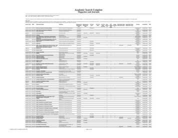
This article has been accepted for inclusion in a future issue of this journal. Content is final as presented, with the exception of pagination.2JOURNAL OF MICROELECTROMECHANICAL SYSTEMSin a variety of microsensors, including micro total analysissystems that use optical emission spectroscopy for chemical sensing [6]–[8], radiation detectors, sputter ion pumps,etc. [9]. Pressure and vacuum sensors based on this method oftransduction utilize the change in plasma distribution withina cavity that may be caused either by a change in theplasma pressure [3] or by the deflection of a plasma electrodeunder external pressure [4]. Sensitivity levels in the range of40,000-75,000 ppm/kPa have been reported [3], which arecomparable to piezoresistive pressure sensors. However, asin capacitive pressure sensors, linearity is compromised. Theinherent signal levels are large compared to both capacitiveand piezoresistive devices, eliminating the need for a proximal interface circuit – and, in fact, substantially reducingthe need for amplification. This is very appealing from theviewpoint of miniaturization. Microdischarge cells that havebeen reported to date are at least 100 smaller in area thanthe smallest capacitive and piezoresistive pressure sensors thathave been reported. For example, the discharge gap in cellsused for plasma display panels can be less than 100 μm [1].Microdischarge-based displays with 50 50 μm2 cell sizehave been reported [11]. Emission spectroscopy of microdischarges for portable chemical sensing of liquids and gases hasbeen reported for 50 μm gaps between planar metal features[12]. A constraint is that microdischarge-based pressure sensors need high voltage to initiate discharges in the operation.This paper1 describes a microdischarge-based approach forthe measurement of diaphragm displacements in a monolithically fabricated device. The exterior volume of the device isonly 0.05 mm3 , which is 30 smaller than prior work [4].The design of the structure is described in Section II, followedby microplasma modeling in Section III. Fabrication processesare addressed in Section IV. Preliminary experiments andresults are provided in Section V.II. D EVICE C ONCEPT AND D ESIGNA. Device ConceptThe device primarily consists of a glass substrate withcopper filled through-glass vias (TGVs), a silicon diaphragm,one anode, and two competing cathodes, as shown in Fig. 1.A microdischarge chamber is formed by the glass substrate,silicon diaphragm, and a Au-In eutectic bond ring. All threeelectrodes are made of thin-film Ni. The anode (A) andreference cathode (K1) are located on the glass side facing themicrodischarge chamber. The sensing cathode (K2) is locatedon the silicon diaphragm, and is electrically connected to theexterior contact pad through a doped silicon layer and the K2contact, which is a sandwich of Au and In layers in the interiorof the chamber that mates with a TGV. All the electricalconnections from within the chamber are routed to the exteriorof the glass substrate through copper filled TGVs. An anodeelectrode placed in the center of the diaphragm would haveprovided the highest electrode displacement. However, giventhe diaphragm area available and the location of referencecathode K1, the anode electrode A is offset from the center.1 Portions of this paper appear in conference abstract form in [13].Fig. 1. Concept of the microdischarge based pressure sensor. (a) 3D modelof the pressure sensor. (b) S-S0 view of the structure. I1 and I2 are dischargecurrents from two discharge paths.In this three-electrode configuration, a voltage pulse is appliedto initiate microdischarges, and two current paths are established between the anode and the two cathodes. (The pulsednature of the microdischarge reduces power consumption andparasitic heating, but requires customized code for simulationsand modeling, as discussed later.) As the diaphragm deflectsdue to external pressure, the spacing between the anode andthe sensing cathode (AK2) decreases, but the spacing betweenthe anode and the reference cathode (AK1) is essentiallyunaffected. This change of interelectrode spacing redistributesthe spatial current: the ratio of sensing current (denoted by I2)between AK2, and reference current (denoted by I1) betweenAK1. The differential current, expressed as a fraction of thetotal peak current (I1-I2)/(I1 I2), can then be used as thesensor output to indicate the value of external pressure. Byusing this relative change in current, the absolute currentbecomes less important, which minimizes the consequence ofpulse-to-pulse variation in microdischarge characteristics.B. Structural DesignThe diaphragm is made of silicon to enable both largediaphragm deflection, within the fracture limit, and electrical conductivity. The eutectic bond ring is 200 μm-wide;it forms a sealed chamber (185 μm-long, 140 μm-wide)and determines the chamber height (and consequently theAK2 interelectrode spacing). With this approach, etching the
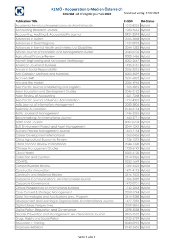
This article has been accepted for inclusion in a future issue of this journal. Content is final as presented, with the exception of pagination.EUN et al.: MICRODISCHARGE-BASED MONOLITHIC PRESSURE SENSOR3Fig. 3. Simulation results of diaphragm deflection at cathode 2 and maximuminduced stress for a 2 μm, 5 μm, and 10 μm thick Si diaphragms.Fig. 2. Paschen curves for various fill-gases, which illustrate the relationshipbetween operating voltage and p · d product, where p is the pressure and d isthe interelectrode spacing. Discharge electrodes are Ni. The original data inthis plot were reported in [20].(1)but not on the metal of the electrodes. The parameter γse is thesecondary electron emission coefficient by ion bombardment,which depends on the metal selected for the electrodes andthe gas. A larger γse lowers the breakdown voltage, which isone of the reasons that Ni is used for the electrodes. For eachchoice of fill-gas in the microdischarge chamber, there is a p·dproduct that corresponds to a minimum voltage for dischargeinitiation. Operating the device near the minimum of Paschen’scurve also has the additional benefit that the energy dissipatedby the discharge is reduced. For this work Ar at 1 atm. ischosen for the fill-gas in the microdischarge chamber, becauseit offers lower operating voltages compared to nitrogen and iscost-effective. Based on this choice of gas and pressure, theAK1 spacing is selected as 10 μm. The AK2 spacing can betailored by adjusting the thickness of the bond ring; it is setat 10 μm and 30 μm in the plasma model and at 30 μm inthe experiments.The thickness of Si diaphragm has a significant influenceon both sensitivity and dynamic range. A thinner diaphragmoffers a high sensitivity but limits the pressure. To determine the appropriate design choice, FEA is performed usingCOMSOL for pressures up to 50 MPa (Fig. 3). A 5 μmthick diaphragm supports a large pressure dynamic rangewhile allowing significant deflection. The deflection of thediaphragm supporting the K2 electrode is up to about 5 μm(0.12 μm/MPa) within the fracture limit, which is a significantfraction of the initial AK2 spacing.It should be noted that even for the smallest nominal AK2gap (10 μm), a full scale diaphragm deflection of 5 μm willonly change the pressure within the microdischarge chamberfrom 1 atm. to about 1.2 atm. This is provided by the followingformulae [21], assuming that the ideal gas law is applicableand the gas inside the chamber is isothermal:Here p is the fill-gas pressure; d is the effective length ofthe breakdown path, approximated by the spacing betweenthe electrodes. A (cm 1 Torr 1 ) and B (V-cm 1 Torr 1) areparameters obtained by fitting the first Townsend coefficient,α (cm 1 ) as a function of E/ p (Electric field/gas pressure),α Ap · exp(-(E/ p)/Bp). A and B depend on the type of gas3 · P(1 v2 )a 4(2)16Eh 32π · a · d(3) V 3where d is the deflection at the center of a circular diaphragm, P is the pressure difference across thesilicon or the glass to form a chamber is avoided. Electrostatic finite element analysis (FEA) using COMSOL confirms that the use of this conductive bond ring as aspacing layer has little or no impact on the electric fieldprofile. The discharge electrodes are made of nickel, whichoffers several benefits, including a high secondary electronemission coefficient (that contributes to a lower operationvoltage), a high resistance to oxidation compared to alternatives [4], a convenient thin film deposition or electroplating, and ease of patterning. The architecture is designedwith the vias in a glass wafer to provide adequate electrical isolation between the electrodes during device operation.This isolation allows the use of operating voltages that are300–500 V or even higher. These vias are filled by copperelectroplating. Prior work on 3D interconnect for integratedcircuits (ICs) has mainly focused on through-silicon vias[14]–[17] for low-voltage devices. Through-glass vias havebeen investigated as means for providing better insulation andlow-cost 3D packaging of ICs [18], [19]. More details of ourapproach to TGV fabrication are described in Section IV.The interelectrode spacing and the thickness of theSi diaphragm are the most critical dimensional parameters ofthe design. The interelectrode spacing, the fill-gas, and theinterior pressure of the chamber determine the discharge initiation (breakdown) voltage. The breakdown voltage betweenplane-parallel electrodes is given by the Paschen curve (Fig. 2)[20]:Vb Bpd.ln Apd ln[ln(1 1/γse )] d
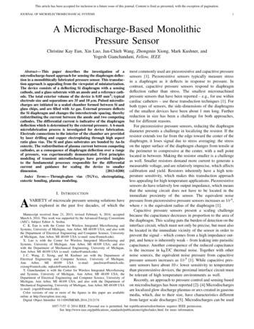
This article has been accepted for inclusion in a future issue of this journal. Content is final as presented, with the exception of pagination.4JOURNAL OF MICROELECTROMECHANICAL SYSTEMSdiaphragm, a is the radius, h is the thickness, v is Poisson’sratio of the material, E is Young’s modulus and V is thevolume change due to deflection.The exterior dimensions of the device are shown in Fig. 1.The total volume of the sensor in the design is 0.05 mm3,whereas the microdischarge chamber is only 2.2 10 4 mm3III. M ICRODISCHARGE M ODELINGFirst principles computer modeling of the microdischargepressure sensor was performed to provide insights to thephysical processes occurring in such devices and to provide guidance in scaling the devices to smaller dimensions.This effort benefited from the availability of a customized2-dimensional multi-fluid hydrodynamic computational platform, nonPDPSIM developed and refined over a number ofyears by three of the co-authors [22], [23]. It solves transportequations for all charged and neutral species in the plasmacoincident with Poisson’s equation for the electric potentialand radiation transport. The fundamental equations for chargedspecies are: q j N j ρs )(4) (ε ) (j Nj · j S j t ρs q j j S j (σ ( )) t(5)(6)jwhere ε, , ρs and σ are the permittivity, electric potential,surface charge density, and conductivity of solid materials;and for species j , the terms N j , j , S j , and q j representcharged species number density, species flux, source function,and charge, respectively. Poisson’s equation [Eq. (4)], thetransport equations for conservation of the charged species j[Eq. (5)], and the material and surface charge balance equation[Eq. (6)] are simultaneously integrated using a sparse-matrixand Newton iteration technique. Poisson’s and charge densityequations are solved throughout the computational domain toaddress electric field penetration into dielectrics. Electricallyfloating metal features are approximated as dielectrics havingsufficiently high conductivities such that the floating featureis equipotential, and there is essentially no internal electricfield within it. The electron energy equation is integrated foraverage energy E ave , (n e E ave ) j ·E · t52 λ Te E i κi Ni n eFig. 4. Schematics of the two geometries of the microdischarge pressuresensor modeled in this effort. (a) The microdischarge chamber for a fullyassembled sensor having a 10 μm gap. The microdischarge chamber has thevertical scale expanded by a factor of 3.3 for clarity. (b) The tested devicewith spacers. The vertical scale is expanded by a factor of 2.e E ave(7)iwhere Te is the electron temperature defined as (2E ave /3),n e is the electron density, κi is the rate coefficient for collisionprocess i with species having density Ni and energy loss E i ,λ is the electron thermal conductivity, and e is the electronflux. Transport and rate coefficients are obtained by solvingBoltzmann’s equation for the electron energy distribution,and constructing a table of coefficients as a function of Te .This table is then interpolated and updated during executionof the model. These electrons are referred to as bulk electrons.Secondary electrons emitted from surfaces and which areaccelerated in the sheaths adjacent to surfaces are referredto as beam electrons. These electrons are tracked using aMonte Carlo simulation. Secondary electrons are emitted fromsurfaces by bombardment by fluxes of ions and UV photons.The computational platform, nonPDPSIM uses an unstructured mesh which enables fine features of the actual devices tobe modeled over a dynamic range of 104 , and so an assessmentof narrowly spaced elements and small features can be made.The finest resolution of the mesh for cases discussed here is0.6-0.8 μm. Although the mesh is static – that is, it doesnot evolve during the calculation – the change in differentialcurrent as a function of pressure can be modeled with aseries of calculations, each with a different deformation ofthe diaphragm. Extensive databases are available for plasmaand neutral reactions occurring in the Ar-filled microdischargechamber [22].Schematics of the two geometries of the microdischargepressure sensor modeled here are in Fig. 4. The microdischargechamber is shown in Fig. 4(a) for a sensor having a 10 μmgap, with the vertical scale expanded by a factor of 3.3 forclarity. The glass has a dielectric constant of ε/ε0 3.9. Thereference cathode (K1) and the anode ( A) are exposed to themicrodischarge chamber with electrodes 1 μm in thicknessand 35 μm wide, separated by 10 μm. The exposed areaof the sensing cathode (K2) is directly under the anode;elsewhere is it covered with dielectric. This configurationrepresents the fully assembled device. The device used forexperimental validation is shown in Fig. 4(b) (with the verticalscale expanded by a factor of 2).The simulated electron density and ionization source bybulk and secondary beam electrons for the device with the
This article has been accepted for inclusion in a future issue of this journal. Content is final as presented, with the exception of pagination.EUN et al.: MICRODISCHARGE-BASED MONOLITHIC PRESSURE SENSORFig. 5. Plasma properties for the microdischarge sensor having a 10 μmgap operating in 1 atm. of Ar with 400 V applied to the anode as a functionof time after application of voltage. (a) Electron density and (b) ionizationsource (the sum of ionization by bulk and secondary beam electrons). Theflood contours are on a log scale over 4 decades. The maximum value in eachframe is noted. (The vertical scale is expanded by a factor of 3.3).10 μm gap are shown in Fig. 5. The ionization source is thevolumetric rate at which electrons and ions are produced bycollisions between electrons and atoms. The fill-gas is 1 atm.(760 Torr) of Ar. For this simulation, the applied voltage onthe anode is 400 V, while the cathodes are grounded. Ballastresistors of 100 , 100 and 500 are assumed, in serieswith K1, K2, and A, respectively. The plasma is initiated by asmall amount of electric field emission of electrons from theedges of K1 and K2 resulting in a negligibly small currentdensity of 10 2 A-cm 2 . These electrons rapidly avalanchein the geometrically enhanced electric fields at the edges ofthe anode. The electron density increases from 109 to nearly1016 cm 3 over a period of 10 ns, creating a conductive plasmain front of the anode. This conductive plasma then reduces theelectric field around the anode, translating the large electricfield to the periphery of the plasma and toward the cathodes.When the plasma reaches K2, ion and photon bombardment ofits surface produces secondary electrons, which are acceleratedback into the plasma and maintain a large rate of ionization.The large electric field directed towards K1 enables the plasmato spread in that direction, eventually covering K1 after about20 ns. Bulk electrons are prevented from reaching K1 and K2by the electrodes’ large negative potential with respect to theplasma, as shown by the gaps in bulk electron density adjacentto K1 and K2 in Fig. 5(a). Current to these electrodes isprovided by the conduction current of ions and displacementcurrent.The simulated electron density and ionization source in thedevice with a 30 μm gap are shown in Fig. 6. Ballast resistorsof 1000 , 1000 and 20 M are assumed, in series with5Fig. 6. Plasma properties for the tested microdischarge sensor having a 30 μmgap operating at 770 Torr of Ar with 480 V applied to the anode as a functionof time after application of voltage. (a) Electron density and (b) ionizationsource (the sum of ionization by bulk and secondary beam electrons). Theflood contours are on a log scale over 5 decades. The maximum value in eachframe is noted. The vertical scale is expanded by a factor of 2.K1, K2, and A, respectively. The pressure is 770 Torr(consistent with the experiments) and the initiating currentdensity from the cathodes is 10 4 A-cm 2 . The voltage onthe anode is assumed to be 480 V with a rise time of 5 ns.Although the trends are similar to the smaller AK2 gap device,there are qualitative differences due to the significantly largergap and ballast resistor. The closer proximity of cathode K1to the anode A initiates the plasma first between these twoelectrodes. The larger gap produces a lower electric fieldbetween K2 and anode A, and so the relative contribution ofelectric field enhancement to ionization at the edges of theelectrodes is greater. The larger ballast resistor produces alarger decrease in voltage across the plasma, since as currentis collected there is a larger voltage drop across the ballastresistor. This reduced voltage, combined with the larger gap,produces a lower electric field in the bulk plasma and a lowerelectron density. A peak value of 1014 cm 3 is observedcompared to nearly 1016 cm 3 for the other compact device.IV. FABRICATIONThe fabrication process requires 6 masks, 3 for glassprocessing (Fig. 7) and 3 for silicon processing (Fig. 8).The glass processing includes the laser-drilling of the TGVs,followed by the filling of the vias using copper electroplating.The next steps include the patterning of the contact pads onthe exterior side of the wafer and the indium bond ring onthe interior side of the discharge chamber. Finally, the Nielectrodes are patterned inside the microdischarge chamber.The silicon processing includes the deposition and patterning
This article has been accepted for inclusion in a future issue of this journal. Content is final as presented, with the exception of pagination.6JOURNAL OF MICROELECTROMECHANICAL SYSTEMSFig. 8.Process sequence for the Si wafer. 1) Silicon dioxide layer isgrown and patterned on SOI for diaphragm insulation, and K2 contact isthen defined. 2) Au bond ring and K2 contact on the interior of SOI waferare electroplated. K2 electrode is deposited by a lift-off process. 3) Eutecticbonding is performed between glass and silicon wafers. 4) Handle wafer isreleased by a backside dry etching.Fig. 7. Process sequence for the glass wafer. 1) Through-holes are laserdrilled. 2) Glass wafer is attached to a dummy Si wafer by eutectic bonding.A 4–6 μm thick electroplated indium layer on the dummy wafer servesas the seed layer for Cu electroplating. 3) Through-holes are filled by Cuelectroplating. 4) A lapping step removes excess Cu and the dummy wafer.5) The contact pads are deposited and patterned on the exterior of the glasswafer. 6) The bond ring and K2 contact are defined on the interior side ofthe glass wafer. The In bond ring is covered with 50 nm Au for protection.7) Electrodes are deposited on the interior of the glass wafer.of an insulating oxide on the Si device layer of a siliconon-insulator (SOI) wafer. This is followed by the patterningof the Au bond ring and K2 electrode. Next, the glass andsilicon chips are aligned and attached using a Au-In eutecticbonding method. Post-bonding, the Si diaphragm is releasedfrom the handle wafer by a deep reactive ion etching (DRIE)process, using the buried oxide layer as the etch stop.A. Glass ProcessingThe glass processing uses 300 μm-thick Schott Borofloat glass wafers. In order to provide electrical contact from thepressure sensor electrodes (located within the sealed chamber) to the contact pads (located outside the chamber), viasare drilled (Precision Microfab, Severna Park, MD) using a193 nm ArF excimer laser. This machining process has a depthcontrol of approximately 5 μm, a lateral precision of 1-2μm,and a profile taper of 88.1 . The actual machined holes are47.5 μm on the exterior side and 15.8 μm on the interior sidefor a machining profile of 87 [Fig. 9(a)].A variety of methods can be used for achieving an electrical connection through the glass vias, including thin-filmdeposition, packing and melting of solder balls or powder, andelectroplating. The high aspect ratios of the TGV structuresmake it impractical to achieve sufficient sidewall coveragefor reliable electrical contacts using thin film deposition.The use of solder particles yields limited success because ofinconsistent reflow when heated to the melting temperature(183 C for 37Pb/63Sn) and beyond (up to 280 C). Althoughthe exact cause of this behavior has not been determined, it ispossibly related to the large ratio of surface area to volume,which is known to prevent recrystallization.Electroplating provides the consistency and scalability forfilling the TGVs. Although a variety of plating metals areavailable, In and Cu are the best candidates for this application.Indium has a low reflow temperature (156 C), which allowstemperature cycling post-plating in order to remove pinholesor voids. Copper offers lower resistivity and a higher platingrate. The higher re-melting temperature can also accommodate
This article has been accepted for inclusion in a future issue of this journal. Content is final as presented, with the exception of pagination.EUN et al.: MICRODISCHARGE-BASED MONOLITHIC PRESSURE SENSOR7The In bond ring (4 μm-thick, coated with a 50 nm-thickAu layer) and one side of K2 contact are then formed byevaporation and lift-off (Fig. 9). The Ti/Ni (20 nm/200 nm)electrodes (34.5 μm-wide) are formed by lift-off achieving anAK1 spacing of approximately 11.1 μm. As shown in Fig. 9(d),the alignment of the TGVs and Ni electrodes is reasonablygood and centered.B. Silicon ProcessingFig. 9. Optical photos of fabricated glass chip. (a) Laser drilled TGVs,out-chamber side. (b) TGVs are electroplated with copper; bond ring and K2contact are patterned with indium and Au protection. (c) Zoom-in view of themicrodischarge chamber. (d) Anode and cathode 1 are patterned with Ti/Nias electrodes by a lift-off process.a higher operating temperature for the pressure sensor. Bothmetals were successfully plated in experimen
Ann Arbor, MI 48109 USA (e-mail: xinluo@umich.edu). J.-C. Wang, Z. Xiong, and M. Kushner are with the Department of Electrical Engineering and Computer Science, University of Michigan, Ann Arbor, MI 48109 USA (e-mail: junchwan@umich.edu; zxiong@umich.edu; mjkush@umich.edu). Y. Gianchandani is with the Center for Wireless Integrated MicroSensing