Transcription
EnVisionNetwork Communications GuideEnVision Network Communications Guide RevBJuly 2013 (V1.0.0)Supersedes: RevA (March 2011)
EnVision1 Getting Started .1.11.1 Hardware Requirements . 1.11.2 Connecting Controllers to EnVision. 1.21.2.11.2.21.2.31.2.41.2.51.2.6Setting the Orion-M Controller Address . 1.2Setting the nCompass CM Controller Address . 1.3Setting the nCompass LC Controller Address . 1.3Setting Single-Loop Controller Communication Parameters . 1.4Setting IO Module Communication Parameters. 1.4Ethernet to Serial Communications Wiring . 1.51.3 Performance Considerations. 1.71.3.1Device Scan Rates. 1.72 PC-E Ethernet TCP/IP-Serial Converter .2.12.1 Modes of Operation. 2.12.2 Configuring the PC-E . 2.22.2.12.2.22.2.32.2.42.2.52.2.6Connecting the PC-E to a Computer . 2.2Viewing the Web Page. 2.3Setting the PC-E Communications Parameters. 2.4PC-E Server Mode Settings (Device Connection) . 2.5PC-E Client Mode Settings (EnVision Modbus Master Connection) . 2.6Assigning a Name to the PC-E . 2.72.3 Installing the PC-E . 2.82.3.12.3.2Connecting the PC-E to a Controller or I/O Module. 2.9Connecting the PC-E to a Computer . 2.102.4 Troubleshooting . 2.112.4.12.4.2Resetting the PC-E to Default IP Address . 2.11PC-E Status LED’s . 2.123 Moxa MB3170 MGate Modbus Master .3.13.1 Configuring the Moxa MGate Modbus Master . 3.13.1.13.1.23.1.33.1.43.1.5Configuring the Serial Port . 3.2Configuring the Network Connection . 3.3Configuring Slave ID (Controller) Mapping . 3.4Customizing Modbus Settings. 3.6Priority Control . 3.6TABLE OF CONTENTSi
EnVision1 Getting StartedEnVision is a SCADA (Supervisory Control and Data Acquisition) package for the Orion-Mi and nCompassCM multi-loop control systems, the nCompass LC dual loop controller, and also provides support for use withFuture Design Controls’ 100, 300 and C-Series single-loop PID controllers, L91/L41 limit controllers, P-Seriesprofile controls and FDC-IO modules. Data from each device can be monitored from the Windows basedEnVision package. Connection to the individual devices is accomplished via an RS485 serial connection orEthernet-to-serial connection.EnVision provides a rich set of tools for control interaction and data analysis. Control data can be viewed indevice detail, faceplate, digital and trend formats. You can change set points, alarm set points and evencreate, save, download and start schedules for any Orion or P-Series controller in the system.The EnVision software package can monitor up to 128 individual devices. Each of the 128 devices, whetheran Orion-M controller, or 300-Series controller for example, can have their data saved to the hard disk atuser-defined rates. Data file analysis tools (digital and trend) make looking at schedule run data a simpletask.EnVision offers 21CFR Part 11 security features for use in Pharmaceutical or any industry that requirescontrolled security access to software functions, encrypted data, electronic signatures and audit trail listings.NOTE:This guide covers the installation of an Ethernet-to-serial communications link for connectingdevices to EnVision. See the EnVision Configuration and User Manuals for information regardingthe setup and activation of each individual device in EnVision. For detailed operation andconfiguration of the Orion-M multi-loop controller or other FDC control product, please see therespective controller manual.1.1Hardware RequirementsPC:OS:minimum 2GHZ Pentium4 with 512MB of RAM.98, NT 2000, XP Professional, Vista and Windows 7 operating systems supported.EnVision will run on a lesser machine but performance may suffer if large trend buffers are used. It isrecommended that a PC with an actual serial port be used. However, since many computers no longerprovide a standard serial port, USB to serial port converters can be used. Note that port assignment for theconverter can change depending upon which USB port it is connected to. Therefore, once the adapter hasbeen connected to the computer and the proper port number is assigned in the EnVision Configurator, theadapter should always remain connected to the same USB port for use with EnVision.Supported Controller Models:Orion-M iSeries and nCompass CM multi-loop, nCompass LC dual loop, 100,300, and C-Series single-loop PID controllers, L91/L41 limit controllers andP-Series profile controls with RS485 communications as well as FDC IO8TCS/6RTD/8AIIS/8AIVS modules.When using Ethernet communications, serial to Ethernet protocol converters are required. Future DesignControls offers the model PC-E converter for this purpose. One PC-E is typically required for each device inthe system. In addition, a Moxa MB3170, MGate Modbus master is required at the PC to address individualcontrollers from the PC’s serial port over the Ethernet network. Each of these devices converts the serialcommunications signals between the PC and individual controllers to an Ethernet protocol format so that anetwork connection can be used.Windows is a registered trademark of the Microsoft CorporationGETTING STARTEDEnVision1.1
EnVision1.2Connecting Controllers to EnVisionConnecting the individual Orion-M, nCompass and single-loop PID controllers to EnVision, involves makingthe proper communication wiring connections and setting the Modbus slave address in each controller that ison the communications link. If the addresses are not set correctly, or multiple controls have the samecommunications address, the system will not work properly. Each controller must have its own uniqueaddress, from 1 to 128, corresponding to the address number (Add#) in the EnVision Configurator.NOTE:1.2.1The location of the controller on the communications network does not matter when assigning thecommunications address. The controller is identified by its address only, not its position when wiredinto the communications link.Setting the Orion-M Controller AddressTo assign the communications address from the Orion-M main view screen, select “System Setup” from theSetup menu. Next, select “Web Server/Modbus/VNC” from the Setup menu. This will display the WebServer/Modbus/VNC screen.Touch the address entry field for the “Modbus Slave Address” and enter the desired address for the controlleron the network. The address entered here, will correspond to the address (device) number in EnVision. Inorder to view the controller in EnVision, the corresponding device address in EnVision must be configured tomatch the Orion-M and be enabled under “Device Setup” in EnVision.The Orion-M can only be assigned addresses in the range of 1-31. When assigning controllers to EnVision,be sure to leave the first 31 addresses open for Orion-M systems. If more than 31 Orion-M systems aregoing to be installed on the communications network, Orion-M controls with the same Modbus slave addressmust be placed on separate PC-E converters. The Moxa, MGate Modbus master can then be configured toassign a controller address of 42 in EnVision for example, to an Orion-M controller with a Modbus slaveaddress of 3 at the IP address of the PC-E converter.The address re-assignment is transparent to EnVision, which allows a total of 128 Orion-M systems to beattached to the network. For additional information regarding the configuration of the MGate Modus master,see Section 3.0, Configuring the MGate Modbus Master of this Guide.1.2EnVisionGETTING STARTED
EnVision1.2.2Setting the nCompass CM Controller AddressTo assign the communications address from the main view screen, select “Settings” from the Device menu.Next, select “Comms” from the Comms settings menu. This will display the Communications screen.Touch the Modbus Address entry field and enter the desired address for the controller on the network. Theaddress entered here, will correspond to the address (device) number in EnVision. In order to view thecontroller in EnVision, the corresponding device address in EnVision must be configured to match thenCompass and be enabled under “Device Setup” in EnVision.The nCompass CM can only be assigned addresses in the range of 1-31. When assigning controllers toEnVision, be sure to leave the first 31 addresses open for nCompass CM controls. If more than 31 controlsare going to be installed on the communications network, nCompass CM controls with the same Modbusaddress must be placed on separate PC-E converters. The Moxa, MGate Modbus master can then beconfigured to assign a controller address of 62 in EnVision for example, to an nCompass CM controller with aModbus address of 9 at the IP address of the PC-E converter.The address re-assignment is transparent to EnVision, which allows a total of 128 nCompass controls to beattached to the network. For additional information regarding the configuration of the MGate Modus master,see Section 3.0, Configuring the MGate Modbus Master of this Guide.1.2.3Setting the nCompass LC Controller AddressTo assign the communications address from the main view screen, select “Settings” from the Device menu.Next, select “Comms” from the Comms settings menu. This will display the Communications screen.GETTING STARTEDEnVision1.3
EnVisionTouch the Modbus Address entry field and enter the desired address for the controller on the network. Theaddress entered here, will correspond to the address (device) number in EnVision. In order to view thecontroller in EnVision, the corresponding device address in EnVision must be configured to match thenCompass and be enabled under “Device Setup” in EnVision. The Parity settings must also be set for “Even”in order to be compatible with EnVision.The nCompass LC can only be assigned addresses in the range of 1-31. When assigning controllers toEnVision, be sure to leave the first 31 addresses open for nCompass LC controls. If more than 31 controlsare going to be installed on the communications network, nCompass LC controls with the same Modbusaddress must be placed on separate PC-E converters. The Moxa, MGate Modbus master can then beconfigured to assign a controller address of 36 in EnVision for example, to an nCompass LC controller with aModbus address of 5 at the IP address of the PC-E converter.The address re-assignment is transparent to EnVision, which allows a total of 128 nCompass controls to beattached to the network. For additional information regarding the configuration of the MGate Modus master,see Section 3.0, Configuring the MGate Modbus Master of this Guide.1.2.4Setting Single-Loop Controller Communication ParametersThe 100, 300, L91/L41, C and P-Series controllers provide additional communications settings for baud rate,data bits, stop bits and parity, in addition to the communications address. For instructions on how to accessthese settings, see the respective controller manual for the model of controller you are using. In order for thecontrollers to communicate with EnVision, set the communication settings to the factory default of 9600 baud,8 data bits, even parity and 1 stop bit as applicable.The communications address entered in the controller will correspond to the address (device) number inEnVision. In order to view the controller in EnVision, the corresponding device address in EnVision must beconfigured to match, and be enabled under “Device Setup” in EnVision.1.2.5Setting IO Module Communication ParametersThe FDC IO-8TCS/6RTD/8AIIS/8AIVS modules must be configured prior to connecting them to the EnVisioncommunications link. This includes setting the thermocouple or RTD type for temperature models, andprogramming the proper communication settings for compatibility with EnVision.NOTE:Analog and voltage input models must be programmed for the 0-4095 input range (input type 1).The EnVision Configurator provides linear scaling for each individual voltage and/or current inputthat allows the user to scale the 0(2)-10V or 0(4)-20mA signal to represent values in engineeringunits.For information regarding the steps involved in configuring the various IO modules, consult the FDC IOManual on using IO Studio software, a free Windows based software package provided by Future Design thatprovides a simple, easy to use interface for configuring all FDC IO modules. The programmedcommunication settings must be set as follows:Baud Rate:Parity:Stop Bit:Reply Delay:9600Even10Once the module as been configured using IO Studio, DIP switch ten (0) must be turned on to activate theprogrammed communication settings so that the module can communicate properly with EnVision. DIPswitches 1-7 must also be set to correspond with the desired address for the IO module on the EnVisioncommunications link.1.4EnVisionGETTING STARTED
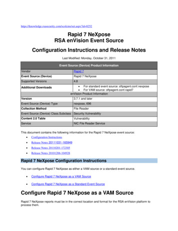
EnVision1.2.6Ethernet to Serial Communications WiringEthernet communication provides a very robust and reliable backbone for controller communications even innoisy environments, and offers a virtually unlimited distance between the controllers and the PC runningEnVision. However, special consideration must be taken when connecting controllers to EnVision over anEthernet network via the PC-E protocol converters.To set up this type of communications link, each PC-E (typically one per controller) is configured with aunique IP address. The IP address must then reference the specific Modbus address of the controller, so thatthe Moxa MB3170, MGate Modbus master can send the proper Modbus command to the correct PC-E inorder to communicate with the controller. In addition, the controller communications network should beseparated from all other networks within the building.While the convenience of Ethernet makes it appear that you can simply connect any device to your networkand make it available, doing so can cause performance issues when using EnVision. In order for EnVision toperform operations such as data logging for example, it must be able to acquire data when needed to log it. Ifthere is heavy network traffic from other devices like printers, a co-worker downloading a large file from theinternet, etc., this can consume most of the network bandwidth at the time EnVision needs to acquire data.Since the network is consumed with other activity, EnVision would not be able to acquire the data it needsand a communications error would result.To insure proper operation, EnVision should be run on an independent Ethernet network to prevent otherbusiness machines from interrupting communications. Setting up the PC to controller network, and the stepsrequired to properly configure the PC-E and Moxa Ethernet to serial converters, is discussed in the followingtwo sections of this guide.GETTING STARTEDEnVision1.5
EnVision1.6EnVisionGETTING STARTED
EnVision1.3Performance ConsiderationsFor each device enabled in EnVision, the software must query data from the controller in order to display theinformation and data log the values. While communications to each individual device happens very quickly,as more devices are added to the communications link, the total amount of time that elapses between eachread of a controller for data increases. This begins to slow the rate at which real-time data can be acquiredand displayed in EnVision.This is not a limitation of the software, but the limitation of the communications link. For a system with asingle Orion-M controller, EnVision can capture and display data as often as every 300ms. However, if tenOrion-M systems were attached at the given 300ms per control, that results in a 3 second scan rate. Thus,EnVision is only able to acquire data for each controller once every 3 seconds. Depending on the desiredreal-time data update rate, it may be necessary to divide the total number of devices between multiple PC’srunning EnVision to keep the total scan time as short as possible.EnVision’s scan rate can be adjusted by the user under Device Setup in the EnVision runtime program. Thisadjusts the polling interval, i.e., the minimum period between commands that EnVision sends to read datafrom each device on the communications link. The scan rate can be adjusted from 100ms to 5000ms (5seconds). The shorter the time period the faster EnVision scans all enabled devices; however, dependingupon the network configuration and controls on the link, the faster scan rate may cause communicationerrors. It also consumes more of the PC’s processor capacity for handling communications rather than datalogging or displaying information. By adjusting the scan rate, the user can balance the system for the bestoverall performance.1.3.1Device Scan RatesIn order to acquire data from each device on the communications link, EnVision must send a “read” commandto tell the device to send the requested information. There is a limit to the amount of data that can be sent ineach response, therefore, certain devices may require more than one read command in order to get allavailable data from the device.The total scan time for each device, i.e., the time it takes to acquire all of the data, is equal to the number ofread commands multiplied by the scan rate set under Device Setup. For example, an FDC IO modulerequires one read command. At a 500ms scan rate, it would take 500ms to acquire the data. An Orion-Mcontroller; however, requires 3 read commands. Using the 500ms scan rate, it would take 1.5 seconds toacquire the data for an Orion-M. The number of devices, the types of devices and the scan rate, all play arole in the total time it takes EnVision to acquire data from all devices enabled in the system.The number of read commands required per device is as follows:Orion-M iSeries Multi-loop Controls nCompass CM Controls nCompass LC Controls 100, 300 and C-Series Controls P-Series Profiling Controls L41/91 Limit Controls FDC IO Modules 3 reads3 reads1 read1 read1 read1 read1 readUsing the information above, it is possible to calculate the minimum amount of time that is required to obtainreal time data updates for any combination of devices. This flexibility allows EnVision to be tailored forvirtually any application from a simple data acquisition system using basic IO modules, to a combinationcentral control and acquisition package by combining Orion-M, limit and single loop controls and IO modules,to make a plant wide monitoring system.GETTING STARTEDEnVision1.7
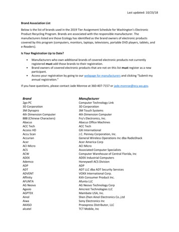
EnVision2 PC-E Ethernet TCP/IP-Serial ConverterThe PC-E, Ethernet TCP/IP-Serial Converter allows serial devices to be connected to an Ethernet network viatheir serial connection. The PC-E converter can be connected to multiple devices, allowing a single PC-E toconnect multiple Orion-M, nCompass, 100, 300 or C and P-Series controllers or I/O modules to an Ethernetnetwork. Using Modbus TCP/IP protocol, each device can then communicate with the PC running EnVision.2.1Modes of OperationThe PC-E converter provides two, primary modes of operation. The standard mode of operation is a serverconfiguration. This is used to connect the controllers or I/O modules to the Ethernet network. In thisconfiguration, the PC-E can accept up to four client connections, i.e., four Modbus TCP/IP masters. Thisallows four different computers, each running their own communications software like EnVision, to access thesame device via the PC-E over the network.The second mode of operation is a client configuration. It allows a computer running typical Modbus serialcommunications software like EnVision, to be connected to a network, and transmit the serial Modbuscommands over the network to a PC-E running in server mode in a remote location that has a device (ormultiple devices) connected to it. This allows an Orion-M, nCompass, I/O module, single-loop controller, etc.,to be connected to the computer running EnVision using an existing network connection without having to runRS485 serial communications wiring from the computer to the controllers.NOTE:The client configuration is only suitable for use with one PC-E in server mode. If there are multipledevices on the network, each with their own PC-E, the Moxa MB3170, MGate Modbus master mustbe used on the PC to address each PC-E separately. The PC-E client mode only allows for a singlePC-E to PC-E connection. If there is only one device to communicate with, or multiple devices areconnected remotely to a single PC-E in server mode, a PC-E in client mode can be used at the PC.PC-E ETHERNET TCP/IP-SERIAL CONVERTEREnVision2.1
EnVision2.2Configuring the PC-EThe PC-E converters are factory programmed with a default IP address of 192.168.0.112. This address mustbe changed before the converter is added to an existing Ethernet network. The IP address in the convertermust be unique in the network, and is changed via its web server.The web server allows the IP address, serial data format and operating modes of the PC-E to be set. Mostweb browsers like Internet Explorer, Netscape, etc., can access the web server. The web page address forviewing the setup parameters is http://192.168.0.112/index.htm and the web page address for configuring theconverter is http://192.168.0.112/ip.htm.2.2.1Connecting the PC-E to a ComputerIn order to configure the PC-E for the first time, a direct connection must be made between a PC and the PCE. The PC-E converter is shipped with a default IP address of 192.168.0.112. For direct connection betweenthe PC and the protocol converter, a crossover Ethernet cable is required. To set up your PC to connectdirectly to the PC-E, an IP address in the same range as the protocol converter must be assigned to the PC.In Windows environments, this can be done as follows:1.2.3.4.2.2Apply power to the PC-E and connect it to the PC using a crossover cableOpen the Windows Control Panel and select Network ConnectionsSelect Local Area Connection and click on the Properties buttonFrom the General Tab, select Internet Protocol (TCP/IP) and click the Properties buttonEnVisionPC-E ETHERNET TCP/IP-SERIAL CONVERTER
EnVisionFrom the Internet Protocol (TCP/IP) Properties page, do the following:5. Choose to specify the IP address by clicking on “Use the following IP address”6. Enter the IP address, subnet mask and default gateway as shown below7. Accept the new settings by clicking on the “OK” buttonNOTE: If you have difficulty or are unsure of how to access the network connection properties of your PC,contact your network administrator for assistance.2.2.2Viewing the Web PageOnce the PC’s network adapter has been set up properly, test the connection to the PC-E by typing thefollowing address into your web browser: http://192.168.0.112/index.htm. If the settings and connection havebeen made properly, the following web page will be displayed.NOTE: If the web page is not displayed, test the network connection from the PC to the PC-E by using theping command. This can be done by opening the Windows start menu, clicking on Run, and typing“ping 192.168.0.112” on the command line. If the PC-E replies to the ping messages, check thesetup of the web browser. If the PC-E is connected to the PC through a firewall, a proxy servershould be selected in the configuration menu. Contact your network administrator for assistance.PC-E ETHERNET TCP/IP-SERIAL CONVERTEREnVision2.3
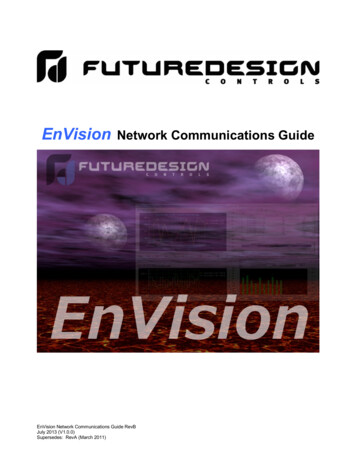
EnVision2.2.3Setting the PC-E Communications ParametersOnce the connection to the PC-E has been verified, access the configuration web page by entering thefollowing address, http://192.168.0.112/ip.htm, into your web browser. The web page will display 3 separatetables; Ethernet Configuration Parameters, Communication Modes and RS232/RS485 Communication PortParameters. Each of these tables contain specific communications parameters that must be set properly forthe PC-E to connect the Orion-M, 100, 300, C or P-Series control, L41/91 limit control or FDC I/O Modules tothe Ethernet network.The Ethernet Configuration Parameters table is at the top of the configuration web page. Note that the PC-Euses a fixed IP address. Regardless of the PC-E mode, server or client, the PC-E IP address must be uniqueand can not be a duplicate of any other address on the network it is going to be connected to.2.4EnVisionPC-E ETHERNET TCP/IP-SERIAL CONVERTER
EnVisionContact your network administrator for an available IP address and the proper defaultgateway and subnet mask to be used for the PC-E network parameters. If a duplicate IPaddress is used or the subnet mask and default gateway are not properly assigned, thePC-E will not be able to communicate over your network.To adjust the settings, enter in the IP address, default gateway and subnet mask assigned for the PC-E byyour network administrator. The socket time out can be left at the default 90 second setting. Once the newvalues have been entered, press the “Submit” button just below the table. This will refresh the web page andsave the settings to the PC-E.IMPORTANT: DO NOT cycle power to the PC-E at this time. Proceed to section 2.2.4, PC-E Server ModeSettings (Device Connection) or section 2.2.5, PC-E Client Mode Settings (EnVision ModbusMaster Connection) to finish the PC-E configuration.The PC-E does not operate under the new Ethernet configuration settings until power iscycled to the PC-E. Once power is cycled, the new IP address assigned under the EthernetConfiguration Parameters must be used to reconnect to the PC-E. If power is cycled prior tocompleting the configuration process, remember to use the new IP address when trying toreconnect to the PC-EAlso note that the TCP/IP settings of your PC’s network adapter may also have to bechanged to correspond with the new PC-E settings in order to establish the connection.2.2.4PC-E Server Mode Settings (Device Connection)The Ethernet Connection Parameters only define the PC-E’s connection to the network, not the connection tothe controller or the mode of operation of the PC-E. To set these settings, the Communication Modes andRS232/RS485 Communications Port Parameters are used. These tables are accessed by scrolling down theconfiguration web page.When the PC-E is used to attach a controller to the network, it must be set for the server mode of operation.By default, the factory communication mode settings are correct and do not need to be changed. Thesettings are as follows:Converter Mode Char Timeout Port Number Server IP 005020.0.0.0 (not applicable for server mode)In order for the PC-E to be able to communicate with the controller over its serial connection, theRS232/RS485 Communications Port Parameters must be according to the controller settings set as follows:Baud Rate Data Bits Parity Stop Bits RS232/RS485 Serial Reply Timeout RS485 On Delay RS485 Off Delay 960081 (even parity)11 (RS485) - can be set to 0 (RS232) for single nCompass LC use100 (sets 1 second timeout – recommended)00NOTE: Remember to press the “Submit” button below the respective settings table to save any changesmade to the parameters. Changes to these settings take affect immediately.PC-E ETHERNET TCP/IP-SERIAL CONVERTEREnVision2.5
EnVision2.2.5PC-E Client Mode Settings (EnVision Modbus Master Connection)The Ethernet Connection Parameters only define the PC-E’s connection to the network, not the connection tothe Modbus Master or the mode of operation of the PC-E
If more than 31 Orion-M systems are going to be installed on the communications network, Orion-M controls with the same Modbus slave address must be placed on separate PC-E converters. The Moxa, MGate Modbus master can then be configured to assign a controller address of 42 in EnVision for example, to an Orion-M controller with a Modbus slave