Transcription
GModBus over TCPUSER GUIDEP.1.1
Table of contents1.Foreword . 32.Configuration . 42.1Software configuration. 42.2Hardware : Network connection . 43.GModBus . 53.14.GModBus over TCP within LabVIEW . 5GModBus over TCP components . 64.1Foreword and writing conventions . 64.2Client tools . 64.2.1Open . 74.2.2Close . 74.2.3Request VIs . 74.2.3.aConnector model . 74.2.3.bRequest 1: Reading of N output bits . 84.2.3.cRequest 2: reading of N input bits . 84.2.3.dRequest 3: reading of N output words . 94.2.3.eRequest 4: reading of N Input words. 94.2.3.fRequest 5: writing of an output bit . 94.2.3.gRequest 6: writing of an output word . 104.2.3.hRequest 15: writing of N output bits . 104.2.3.iRequest 16: writing of N output words. 104.2.4Advanced palette . 114.2.5EZ Coding VIs . 114.3Server tools . 124.3.1Connections scanning. 124.3.1.aInitialization of the scanning . 134.3.1.bListening of the connections . 134.3.1.cStop of the scanning . 134.3.2Requests management . 144.3.2.aRequests reception. 144.3.2.bConnector model of answer to the requests VIs . 144.3.2.cAnswer to requests 1 and 2 (reading N input or output bits) . 154.3.2.dAnswer to requests 3 and 4 (reading N input or output words) . 15P.1
4.3.2.eAnswer to request 5 (writing an output bit) . 154.3.2.fAnswer to request 6 (writing an output word) . 154.3.2.gAnswer to request 15 (writing N output bits) . 164.3.2.hAnswer to request 16 (writing of N output words) . 164.3.2.iGeneration of an exception code . 164.4Tools . 164.4.1GModBus . 184.4.2GModBus over TCP server. 205.GModBus over TCP activation . 226.GModBus over TCP support . 237.GModBus over TCP driver errors . 248.7.1Specific errors . 247.2Exception codes . 24Frequently asked questions . 25P.2
1. ForewordTCP/IP ModBus protocol is a communication protocol based on a client serverstructure. The network can be composed of several clients and several serversconnected with a RJ45 link. One or several ModBus networks can be implemented on asame platform.Through this protocol, only the client can prompt the exchange with the server bysending a request and waiting for an answer. The validity of the communication iscontrolled by the TCP/IP layer.GModBus over TCP driver encapsulates all these layers in order to make it easy forthe developer to insert a computer, as client or server, within such a network.The following functionalities, hidden to the user, are managed:-Link and Network low layers of ModBus procedureEncoding/decoding ModBus framesFrames control through identification and timeoutTCP/IP communication managementP.3
2. Configuration2.1 Software configurationdriver runs under the following LabVIEW:-2010 and laterAnd on the following platforms:-PC under Windows XP and laterRT system (Real Time)2.2 Hardware : Network connectionThere are 2 ways to connect a computer to an Ethernet ModBus network:--Point to point link:The computer and the equipment are networked through a « crossed » Ethernetwire.Ethernet network:The computer is connected to an existing network through a straight Ethernetwire.P.4
3. GModBus3.1 GModBus over TCP within LabVIEWGModBus over TCP driver installation adds the GModBus over TCP palette toLabVIEW functions palette.Figure 1 : "GModBus over TCP" within LabVIEW functions paletteP.5
4. GModBus over TCP components4.1 Foreword and writing conventionsThe set of VIs that composesbelow:driver follows the connector modelFigure 2 : Connector model of-over TCP drivererror in: describes the error conditions found before the VI. The default valuecorresponds to "no error". If an error is transmitted to the error in input of theVI, this error is relayed to error out without the VI executing its function. If anerror occurs when the function is running, this error is automatically relayed toerror out .The connectors respect LabVIEW conventions as follows:The label connectorname (x) means x is the default value associated with thisconnector if no other value is conveyed to its Input.The connectors which names appear in bold in the context help of a VI must bewired. Otherwise the caller VI will not be able to run (broken arrow).4.2 Client toolsThis chapter describes the VIs to use to realise a client for a ModBus network. These VIsare found in the Functions palette by selecting Functions SAPHIR Client Tools.Figure 3: Clients VIs paletteP.6
4.2.1 OpenFigure 4: MBVTCP open.viThis VI initializes the TCP/IP communication described by Network. NetRefTCP out ,unique reference to the network, is required by the other GModBus over TCP VIsmanaging the same client.-Network: input is defined by the two following elements:- Server address: IP address of the server concerned by the requests (ex-:196.168.25.42).Remote port (502) : port used for the TCP/IP communication.If the connection is not opened within the time defined by timeout ms (60000) , the VIgenerates an error.4.2.2 CloseFigure 5: MBVTCP close.viThis VI closes the TCP/IP communication of the Network associated with NetRef in .It is imperative for the release process to be done properly to free the memoryresources of the computer.4.2.3 Request VIs4.2.3.a Connector modelThe set of VIs that composes the Client part ofconnector model below:driver follows theFigure 6: Connector model of Clients VIs-NetRefTCP in / NetRefTCP out : NetRefTCP in is the reference to the ModBusnetwork obtained at the opening of the communication (cf § 4.2.1-) NetRefTCPout is a copy of NetRefTCP in .P.7
--error in / error out : error in describes the errors conditions found before theVI. The default value corresponds to "no error". If an error is transmitted to theerror in input of the VI, this error is relayed to error out without the VI executingits function. If an error occurs when the function is running, this error isautomatically relayed to error out .Timeout : If the client request does not get any response within the time definedby timeout ms (10000) , the VI exits with an error.Unit identifier (x1): is used for the communication with a serial networkthrough a gateway.Information out: is a cluster that contains the following information:Unit Identifier: Identical to Unit identifier (x1).exceptionCode: Code refering to ModBus protocol exceptions (cf. § 7.2). Thedefault value is 0: no exception occurred.functionCode: Number of the used requestsendFrame: String sent to the server equipment. (This data is given forinformation,driver deals with the sending of the frame byitself).receivedFrame: String received by the client (sent by the server as an answerto the request)4.2.3.b Request 1: Reading of N output bitsFigure 7: MBVTCP lecNBitsSortie(1).viThis VI is used to read consecutive output Bits defined in the memory of the destinationserver.-Bit address : address of the first bitQuantity of bits (1): number of bits to readBits: value of the read bits4.2.3.c Request 2: reading of N input bitsFigure 8: MBVTCP lecNBitsEntree(2).viThis VI is used to read consecutive input Bits defined in the memory of the destinationserver.-Bit address: address of the first bitQuantity of bits (1) : the number of bits to readP.8
-Bits: value of the read bits4.2.3.d Request 3: reading of N output wordsFigure 9: MBVTCP lecNMotsSortie(3).viThis VI is used to read consecutive output Words defined in the memory of thedestination server.-Word address: address of the first wordQuantity of Words (1): number of words to readWords value of the read words4.2.3.e Request 4: reading of N Input wordsFigure 10: MBVTCP lecNMotsEntree(4).viThis VI is used to read consecutive input Words defined in the memory of thedestination server.-Word address: address of the first wordQuantity of Words (1): number of words to readWords: value of the read words4.2.3.f Request 5: writing of an output bitFigure 11: MBVTCP ecrBitSortie(5).viThis VI is used to write (at 0 or at 1) an output Bit in the memory of the destinationserver.-Bit address : address of the bit to writeBit (F): value of the bit to writeP.9
4.2.3.g Request 6: writing of an output wordFigure 12: MBVTCP ecrMotSortie(6).viThis VI is used to write an output Word in the memory of the destination server.-Word address: address of the word to writeWord (0) : value of the word to write4.2.3.h Request 15: writing of N output bitsFigure 13: MBVTCP ecrNBitsSortie(15).viThis VI is used to write (at 0 or at 1) a group of consecutive output bits in the memoryof the destination server.-Bit address : address of the first bit to writeBits: number of bits to write and their valuesThe driver sends groups of 8 bits. If the number of bits written is not a multiple of 8,the driver fills the missing bits as FALSE. Depending on the equipment of destination,these bits can be interpreted or not.4.2.3.iRequest 16: writing of N output wordsFigure 14: MBVTCP ecrNmotsSortie(16).viThis VI is used to write a group of consecutive output words (16 bits) in the memory ofthe destination server.-Word address : address of the first word to writeWords: number of words to write and their valuesP.10
4.2.4 Advanced paletteThese VIs manage basics communication functions and make it possible to gainperformance in comparison with the requests VIs that are more high level.The MBVTCP SendRequest.vi sends a request to a ModBus server and returns areference to this request through the Expected answer field. This reference is used toget the associate answer with MBVTCP ReceiveResponse.vi.The Send frame is given just for information.According to the request type the type of data received will be different (some data inthe dataReceived frame may be empty).These functions could be useful in some specific use case performance or4.2.5 EZ Coding VIsEZ Coding VIs are to be dropped on an existing VI. They propose a starting architectureto the implementation of a ModBus client.Drop this VI into the block diagram to place his content and customized it.This code implements a simple request to a ModBus server.P.11
This code implements a way to interpret 2 words to obtain a single.This code implements a way to interpret a single to obtain 2 words.4.3 Server toolsThis chapter describes the VIs to use to realise a Server for ModBus network. These VIsare found in the Functions palette by selecting Functions SAPHIR Server Tools.Figure 15: Server VIs paletteIn Server mode, the computer never initiates the communication. It carries out threedifferent tasks:-Receive the requests sent by the clients.Answer to the clients' requests.4.3.1 Connections scanningThe scanning of the clients' connections and the managing of the communicationswith the clients must be carried out independently.P.12
The three following VIs are used to implement the scanning of the differentconnections to the server.4.3.1.a Initialization of the scanningFigure 16: MBVTCP initializeListener.vi-port (502): number of the port to scan.listener ID out: reference needed for the scanning of the connections.4.3.1.b Listening of the connectionsFigure 17: MBVTCP listenConnections.vi-listener ID in: reference obtained during the initialization of the listening.TimeOut ms (1000): maximum time to wait for a connection.listener ID out: copy of listener ID in .[connections out]: array containing the TCP/IP communication reference(NetRefTCP out) and the IP address (remote address) of each client connectedto the server.# of connections in progress: number of clients connected to the server.4.3.1.c Stop of the scanningVI.When you stop the server, you must close the listener ID reference with the aboveThis process makes it possible to release properly the memory resources of thecomputer.Figure 18: MBVTCP closeListener.vi-listener ID in: reference to close.P.13
4.3.2 Requests management4.3.2.a Requests receptionThe reception of the requests sent by the client(s) is carried out with the following VI:Figure 19: MBVTCP listenRequest.vi-[received request] returns a table of which each element describes the request-Connection ID: TCP/IP reference of the client who sent the request.remote address: IP address of the client who sent the request.receivedFrame : String written in the request.Transaction Identifier: Specific number of the request sent by the client-received :allowing identifying the answer to send.Unit Identifier: identifies a client located on a serial network andcommunicating through the Ethernet network.exceptionCode: Code refering to ModBus protocol exceptions (cf. §7.2). 0 bydefault, no exception occured.functionCode: Number of the request sent.data : Data contained in the request.# of received request: number of requests received.After receiving a request, the answer must be sent as soon as possible to avoidtimeout errors on the Client side.4.3.2.b Connector model of answer to the requests VIsThe set of VIs that composes the answer request part offollows the connector model below:driverFigure 20: Connector model of answer to requests VIs-Received request: contains data about the processed request.Error in: describes the errors conditions found before the VI. The default valuecorresponds to "no error". If an error is transmitted to the error in input of theVI, this error is relayed to error out without the VI executing its function. If anerror occurs when the function is running, this error is automatically relayed toerror out .P.14
-Send frame: describes the frame sent by the server to the client. (This data isgiven just for information)4.3.2.c Answer to requests 1 and 2 (reading N input or output bits)Figure 21: MBVTCP repLectureNBits(1 2).viThis VI permits to answer to the requests 1 or 2 sent by the client through ModBusnetwork.-Bits: array containing the values of all the registers of the server4.3.2.d Answer to requests 3 and 4 (reading N input or output words)Figure 22: MBVTCP repLectureNMots(3 4).viThis VI permits to answer to the requests 3 or 4 sent by the client through ModBusnetwork-Words: array containing the values of all the registers of the server4.3.2.e Answer to request 5 (writing an output bit)Figure 23: MBV repEcritureBit(5).viThis VI permits to answer to request 5 sent by the client through ModBus network.-Bits in: array containing the values of all the registers of the serverBits out: values of the server registers after the processing of the request4.3.2.f Answer to request 6 (writing an output word)Figure 24: MBVTCP repEcritureMot(6).viThis VI is used to write an output Word in the memory of the destination server.P.15
-Word address: address of the word to writeWord (0) : value of the word to write4.3.2.g Answer to request 15 (writing N output bits)Figure 25: MBVTCP repEcritureNBits(15).viThis VI permits to answer to request 15 sent by the client through ModBus network.-Bits in : array containing the values of all the registers of the serverBits out : values of the server registers after the processing of the request4.3.2.h Answer to request 16 (writing of N output words)Figure 26: MBV repEcritureNMots(16).viThis VI permits to answer to request 16 sent by the client through ModBus network.-Words in: array containing the values of all the registers of the serverWords out : values of the server registers after the processing of the request4.3.2.iGeneration of an exception codeFigure 27: MBV repException.viThis VI returns an exception to a ModBus network client in case its request is notsupported by the server.-Exception Code: Code of the exception to send (cf § 7.2).4.4 ToolsThis chapter describes tools to quickly simulate a ModBus client or server. You will findthem in the LabVIEW Tools menu bar.P.16
Figure 28: Tools to simulate ModBus network elementsP.17
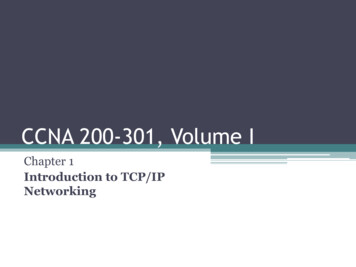
4.4.1 GModBus« GModBus over TCP » will quickly test the communication with a server through ModBusnetwork.Figure 29: Client windowThe interface falls into two sections:-Network settings: defines the TCP/IP parameters of the ModBus network:Server address: IP address of the server to test.Remote port: Number of the port used for the TCP/IP communication.Timeout (in ms): maximum time to wait to receive the server answer.P.18
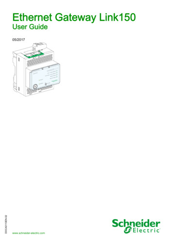
Communication testRequest parametersRequest dataContent of the sentand received framesFigure 30: Counication test interface in Client modeAll the types of Request of GModBus over TCP driver are managed:Figure 31: Requests choiceUnit Identifier identifies an equipment located on a serial network andcommunicating through the Ethernet network. If the contacted server is on theEthernet network, keep the FF hexadecimal value (256 in decimal).The first register to read or write is defined by From address.The field With N is only available for requests 1, 2, 3 and 4. It represents thenumber of bit(s) or word(s) to read or to write.The data zone, located below the request parameters, permits to determine thevalues to write during the use of writing requests.When all the settings are done, click on SEND REQUEST button to start thecommunication with the server. The content of the frames sent and received by theclient is displayed below the data zone.The Exception code refers to ModBus protocol exceptions (cf. §7.2).P.19
4.4.2 GModBus over TCP server« GModBus over TCP Server» application simulates a server of which registers arerepresented with an array of bits and an array of words.A ModBus network client can read or write these tables.Figure 32: Server windowThree sections compose this interface:The Network settings permits to configure the ModBus server parameters:Remote port (502): Ethernet communication port of the serverTimeout (in ms): time left for each scanning of the Ethernet port.When clicking on the RUN SERVER button the server begins to scan the client sconnections (listening state).This change of state is notified by the computer icon which becomes green.The address and the Connection ID of the connected clients are displayed inthe array besides.P.20
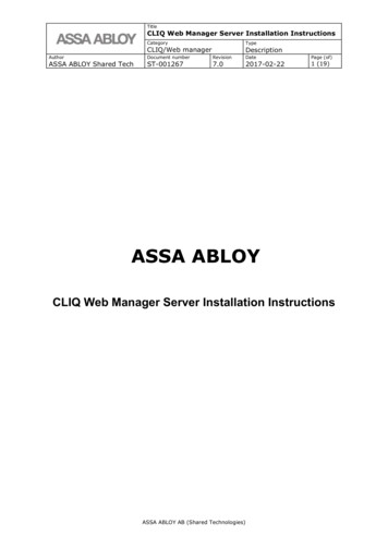
The received and sent frames are displayed in hexadecimal code below the registertables.timeout determines the maximum time itcould take.Table ofwordsTable ofbitsReceived andSent framesList of current connectionsFigure 33: Communication test interface of the serverThe Exception cod refers to ModBus protocol exceptions (cf. §7.2).P.21
5. GModBus over TCP activationAfter the download and installation of GModBus over TCP toolkit, an activation windowwill pop up at LabVIEW launching. Follow the steps of the add-on activation as shown in thepicture below.Figure 34: Third Party Add-onYou can tryduring 30 days. After thisbecome broken. To activate the toolkit after this period, simply go to Help menu and selectActivate Add-P.22
6. GModBus over TCP ps/saphir-toolkitOn these pages, you can find documentation or start discussions with other users ofthe toolkit.Figure 35: Online supportFor direct contact with SAPHIR support team, send us an e-mail atsupport@saphir.fr.P.23
7. GModBus over TCP driver errors7.1 Specific errorsFollowing errors can be generate byfunctionsErrorExplanation6101TimeOut error.6102Unable to connect server.6103Connection rejected by the server.6104The function used to answer the request is not adapted to the request.Figure 36: Specific errors7.2 Exception codesFollowing exception codes are specific to ModBus protocol.Decimal CodesExplanation1Not implemented function2Out of limits address3Out of limits data4Defective equipment5Acquit/release.6Busy equipment7Impossible to release8Memory errorFigure 37: Exception codesWhen an exceptionP.24
8. Frequently asked questionsThe list below collects the most common problems encountered during theimplementation ofdriver:Network setting:The IP address keyboarded must not contains any non-significant zero(ex : 192.168.011.002 192.168.11.2).The values returned by the server do not correspond to the expected values:To return a float number (point) 32 or 64 bits, the server uses respectively 2 or 4words. The Figure below shows the most common way to interpret 2 words to make a32 bits float (number).Figure 38: Interpretation of 2 words in 32 bits floatThe way to interpret words can change according to the type of server. For moreP.25
INDEXFigure 1 : "GModBus over TCP" within LabVIEW functions palette . 5. 6Figure 3: Clients VIs palette . 6Figure 4: MBVTCP open.vi . 7Figure 5: MBVTCP close.vi . 7Figure 6: Connector model of Clients VIs . 7Figure 7: MBVTCP lecNBitsSortie(1).vi . 8Figure 8: MBVTCP lecNBitsEntree(2).vi . 8Figure 9: MBVTCP lecNMotsSortie(3).vi . 9Figure 10: MBVTCP lecNMotsEntree(4).vi. 9Figure 11: MBVTCP ecrBitSortie(5).vi . 9Figure 12: MBVTCP ecrMotSortie(6).vi . 10Figure 13: MBVTCP ecrNBitsSortie(15).vi . 10Figure 14: MBVTCP ecrNmotsSortie(16).vi . 10Figure 15: Server VIs palette . 12Figure 16: MBVTCP initializeListener.vi . 13Figure 17: MBVTCP listenConnections.vi . 13Figure 18: MBVTCP closeListener.vi . 13Figure 19: MBVTCP listenRequest.vi . 14Figure 20: Connector model of answer to requests VIs . 14Figure 21: MBVTCP repLectureNBits(1 2).vi . 15Figure 22: MBVTCP repLectureNMots(3 4).vi . 15Figure 23: MBV repEcritureBit(5).vi . 15Figure 24: MBVTCP repEcritureMot(6).vi . 15Figure 25: MBVTCP repEcritureNBits(15).vi . 16Figure 26: MBV repEcritureNMots(16).vi . 16Figure 27: MBV repException.vi . 16Figure 28: Tools to simulate ModBus network elements . 17Figure 29: Client window . 18Figure 31: Requests choice . 19Figure 30: Counication test interface in Client mode . 19Figure 32: Server window . 20Figure 33: Communication test interface of the server . 21Figure 34: Third Party Add-on. 22Figure 35: Online support. 23Figure 36: Specific errors . 24Figure 37: Exception codes . 24Figure 38: Interpretation of 2 words in 32 bits float . 25P.26
Other add-ons that could be helpful
TCP/IP ModBus protocol is a communication protocol based on a client server structure. The network can be composed of several clients and several servers connected with a RJ45 link. One or several ModBus networks can be implemented on a same platform. Through this protocol, only the client can prompt the exchange with the server by