Transcription
Ozden Supplement for 6/055/9/0510:40 AMPage 94WELDING RESEARCHService Life of Tungsten Electrodes inHyperbaric Dry Underwater WeldingService life diagrams were developed for two types ofcommonly used tungsten electrodesBY H. OZDEN AND K. T. GURSELABSTRACT. In hyperbaric dry underwater welding, the hyperbaric gas tungstenarc welding (GTAW) procedure offersmany advantages. However, determination of the electrode service life is a substantial condition for good results in unmannedandcomputer-remotecontrolled hyperbaric GTAW. Electrodeservice life is the time in which one electrode can be welded from a polished stateto reaching a wear mark as an applied condition criterion under certain conditions.Extending electrode service life can drastically reduce the cost of the process; however, many influencing factors, as well asunpredictable occurrences during hyperbaric GTAW, make exact determination ofthe electrode service life more difficult. Inthis study, electrode service life was examined in the dependence on the electrodetype, arc current, and arc power under different ambient pressure levels. For determining service life of the electrodes in hyperbaric GTAW, wear rate (percentageshortening of the electrode point due towear) was considered as an evaluation criterion, because the wear rate contains allof the above-mentioned parameters andreflects all the effects of them.For the delimitation of the service lifetests, two kinds of tungsten electrodes[WL10 (with 1.0% LaO2) and WT 20 (with2.0% ThO2)] were selected, which are thetypes predominantly preferred in practice.The results of this work indicate that theelectrode service life heavily depends onthe type of electrode under high ambientpressure. The WL10 electrode exhibits alonger arc-on time and a greater electricalload capacity and, therefore, a longer service life than the WT20 electrode. Thecompiled formulas for the computation ofthe electrode service life have an empirical form, which can be used for estimationas well as for comparison of the service lifeof electrodes in hyperbaric GTAW. Theprovided service life diagrams as a funcH. OZDEN and K. T. GURSEL are with the Mechanical Engineering Department, Faculty of Engineering, Ege University, Izmir, Turkey.9494 -s-S JUNE 2005tion of ambient pressure and arc power, inwhich the test results are represented, canbe of great relevance for use both in onshore and offshore technology, especiallyin performing reproducible, high-qualitywelded underwater joints.IntroductionThe intensified use of computers inwelding makes it necessary to collaterallyimprove the pertinent peripheral devicesand to adapt to the new requirements. Forexample, in fully mechanized hyperbaricGTAW, exact determination of the electrode service life as a function of the procedure and electrode parameters is veryimportant, because service life has crucialeffects on performing good, reproducibleweld joints and the cost of the procedure,especially for underwater welding in deepwater where remote control is necessary.Barely any literature can be founddealing with the determination and calculation of electrode service life in hyperbaric GTAW. Some investigations on electrode service life in spot welding areavailable, but, in practice, these are hardlyapplicable to hyperbaric GTAW (Refs.1–11). The aim of this study is to make acontribution regarding the questionsabout electrode service life in hyperbaricGTAW in both onshore and offshore conditions.Problems in DeterminingElectrode Service LifeThe electrode service life tEl is the timein which one electrode can be welded fromKEY WORDSService LifeTungsten ElectrodeHyperbaric GTAWUnderwater Weldinga polished state to reaching a wear markas an applied condition criterion undercertain conditions. Apart from the servicelife, different condition sizes such as weldbead (crawler) length, joint surface, andjoint volume can be consulted for evaluating the serviceability of an electrode. Theelectrode service life depends essentiallyon the following parameters (Refs. 1–11): Process variables (especially arc current,arc voltage) Inert gas type Electrode parameters (type, dimensions, tip included angle, diameter, andsurface of the electrode) Cooling of the electrode (water cooled) Ignition parameters, ignition of the arc Environmental medium.The numerous variables of influenceand their mutual relations make an exactmathematical description of electrode service life more difficult. In addition, themissing guidelines for determining servicelife hinder the accurate definition of theproblem. An exact experimental servicelife determination of the electrodes is connected with a high expenditure of material and time (Refs. 6, 7, 10). Hence, themain objective of the present study is toexamine the service life of tungsten electrodes in the dependence on the electrodetypes, arc current, and arc power underdifferent ambient pressures.In normal current load, the lifespan ofan electrode can persist several days.However, the degradation of arc stabilityresulting from electrode wear can be corrected by adjusting the parameters such asincreasing the arc current or decreasingthe welding speed and the arc length. Ifthe required joint quality cannot be ensured with the electrode under high ambient pressure due to the wear, it should bewelded under lower ambient pressure.Further, the selection of the wear mark fora condition criterion is pressure dependent and can be different according toproducible joint quality and welding type.In determining the service life of electrodes, an accurate definition of theircharacteristics and features is necessary
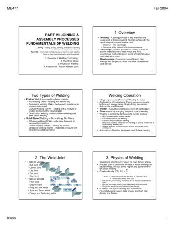
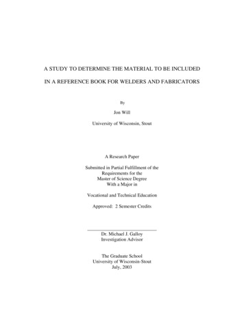
Ozden Supplement for 6/055/9/0510:40 AMPage 95WELDING RESEARCHfor the serviceability of the electrodes incertain weld joint quality. If strong shortening and rounding of the electrode pointas well as wear debris at the electrodepoint occur, the electrode must be replaced. However, shortening of the electrode point due to electrode wear cannotbe an exclusive criterion for determiningservice life. In addition, for preservationof permissible joint quality, the arising deformations and pollutions are also of importance. In the examples shown in Figs.1 and 2, different wear features such asdeformations at the electrode point arerepresented. After arc ignition, a ballforms at the electrode point. The formation of such a slight blunt end extends theservice life of the electrode and enablesstabilization of the arc-on time as shownin Fig. 2, Field III. The service life is alsoextended substantially with aftertreatment of the surfaces of the electrodepoints — Fig. 2, Field II. With increasedpollutants and wear debris at the electrode point, the instability of the arc increases; this effect becomes drastic withincreasing ambient pressure (Refs. 3–6,10, 11). The wear debris descends in thecourse of time into the melting bath, andthus, weld joint quality is reduced. Furthermore, the gradual wear of the electrode point accelerates — Fig. 2, Field IV.Fig. 1 — Electrode wear; 1 — before welding, 2–12 — after welding.Fig. 2 — Electrode ends and point surfaces. I — Unpolished; II — polished; III — ball; IV — erosionat the electrode point.Service Life CriteriaFor determining service life of tungsten electrodes in underwater welding, thefollowing evaluation criteria are used: Wear rate VR in % (percentage shortening of the electrode point due towear), Rounding diameters of the electrodeend in mm, Increased instability of the welding arcin %, Increased arc voltage in %, Uniform weld bead formation, Modification of the shape of the core arc(as seen in Fig. 3), Electrode temperature in C.Electrode wear influences arc instabilityand the rise of the arc voltage more effectively when the ambient pressure increases (Refs. 1–11). The occurring voltage fluctuations as well as the arcdiversions in frequency and height can beconsulted as criteria for the service life determination of the electrodes. These service life criteria can be an advantage infully automated hyperbaric GTAW, inwhich the electrode change can take placeautomatically after reaching these servicelife criteria with or without inquiries. Figure 4 schematically represents the types ofwear. From this, the percentage wear ratecan be calculated as follows:Fig. 3 — Close-up view of the arc and the electrode during welding. A — Shortly after arc ignition; B —during buildup welding; C — passes with filler metal; D — electrode point burned strongly during fillerpass.VR1 100VR2 100VDd ElVT(1)SL 100VD2 SLcotb(2)2where VR1 is the wear rate of the electrodein % under consideration of electrodepoint length, VR2 is the wear rate in %under consideration of the electrode pointdiameter, VT is shortening of the electrode point in mm, VD is the wear diameter (i.e., final state of the electrode pointdiameter in mm), SL is the electrode pointlength in mm before welding, dEl is theelectrode diameter in mm, and b is the tipincluded angle in degrees — Fig. 4.The temperature in the electrode pointdepends on the type, the dimensions, andthe cooling of the electrode when weldingparameters are held constant. With longerarc-on time or higher current rate, the sustainable heat capacity can be exceededdue to the Joule’s resistance heating according to Equation 3.Q UIt I 2 Rt U 2tR(3)where Q is arc energy in J W.s, U is arcvoltage in V, I is arc current in A, R is electrical resistance of the electrode in ohms,and t is the duration of the current flow inseconds.Apart from the current heating theelectrode, thermal conduction from thearc to the electrode and the radiant heatof the arc contribute to its heating. Ac-WELDING JOURNAL 9595 -s-S
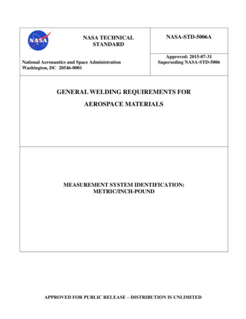
Ozden Supplement for 6/055/9/0510:40 AMPage 96WELDING RESEARCHtests, percentage shortening of the electrode point was selected as a main condition criterion because the wear rate contains all the parameters mentioned in theprevious sections and reflects all the effects of them.Tests for Determining ElectrodeService LifeFig. 4 — Wear dimensions at the electrode point.Fig. 5 — Computer numerically remote-controlled GTAW device of the hyperbaric pressure chamber.cording to an equation for the heat development in the electrode, the current heatincreases with cubic power of time. Equation 4 after Aman (Ref. 1) can be used toqualitatively compare the GTAW electrodesQ1 0.24specific heat c, density s, and electricalconductivity s during the entire weldingtime t as follows:DT QIs I 2cs q 2t[ C](5)I 2 L0qt0 È0.39 3t - 0.1t0 t calÍ 0.53t 3 ÍÎt0[ ](4)where Q1 is the theoretical amount of heatwithout losses, which is developed in theelectrode within the time interval betweenthe beginning t0 and end of welding t; I isthe arc current, and q is the electrode crosssection.Equation 5 gives the temperature riseDT in C in the electrode as a function of9696 -s-S JUNE 2005Long arc-on time and high current loadcan lead to a fast destruction of the electrode point and, thus, to instabilities in thearc and weld joint errors. Therefore, it ispossible that the electrode temperaturecan be regarded as a condition criterion.Selection of the condition criterion depends especially on the test conditions.The choice of a wear mark on electrodesin different pressure levels resulted in difficulties, because a “new” wear mark ineach test should be determined dependingupon ambient pressure. For the followingBoth long-term and short-term testsfor determining electrode service life canbe performed. In long-term tests, servicelife values can be determined more precisely than in short-term tests. Because ofthe high expenditure of materials andtime, short-term service life tests wereused for this study. In these tests, sufficiently exact reference values could alsobe obtained. Depending upon the testaim, service life tests with current load orwear were executed. In the test with current load, the electrode was loaded in acertain time period with different amperages. The rising electrode wear was determined for comparison and extrapolatedfor longer periods of operation. In the service life test according to wear, the timeperiod in which a respective wear criterionlimit applied under certain welding conditions was achieved was measured. In orderto shorten the test duration, one operateswith higher amperages and standard welding values.The test facilities consisted of a hyperbaric welding chamber, energy and gassupply system, and testing devices forwelding, control, and monitoring as well asdocumentation. A pressure chamber witha volume of 10 m3, a swivel-mounted andCNC remote-controlled welding device, awater cooler, and smoke filter made upthe hyperbaric welding chamber — Fig. 5.In the tests, the buildup and joint weldingwere accomplished with V joint preparation for all welding positions in differentwater depths. Basic material S235JR (EN10025) steel with a thickness of 15 mm wasused. In direct current operation, the arccurrent was increased gradually from 50 to300 A. Argon with a 4.6 grade and a mixture of argon and helium as shielding gas,as well as a “tri mix” (He, CO2, and N2)mixture as chamber gas were used. TheGTAW machine with water cooling usedin the test had a ceramic 10-mm-diameterinert gas nozzle. For the investigations,GTAW electrodes WT 20 and WL 10 withtip included angles of 30, 45, and 60 deg(EN 26848) and with diameters of 3.2 and4.0 mm were selected — Fig. 4. The electrodes were abraded mechanically and accurately polished with a diamond disk.The contact ignition of the electrodes,which had proved more favorable thanhigh-frequency ignition in hyperbaricGTAW conditions, took place alterna-
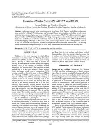
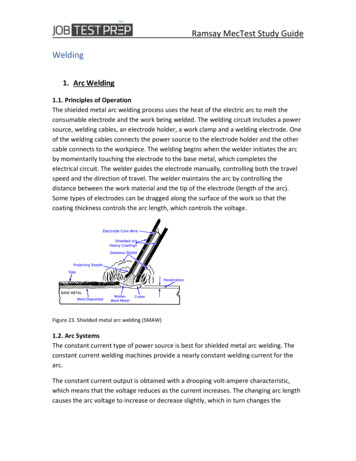
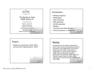
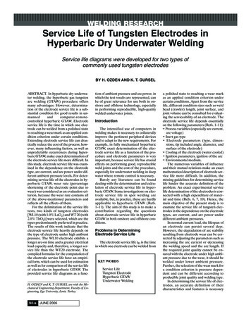
Ozden Supplement for 6/055/9/0510:40 AMPage 97WELDING RESEARCHHyperbaric GTAWHyperbaric GTAWFig. 6 — Percentage of wear rate as a function of arc-on time and ambient pressure at the electrode point.tively on a Cu sheet metal or on the workpiece with an arc length of 4 mm that waskept constant by an arc voltage control device — Fig. 3A. The prepared CNC program prevented excessive mechanical orelectrical loading and, thus, possible damage to the electrode points during the ignition process.Test Results and DiscussionA significant characteristic of electrode wear arises in the beginning of thetest with the ignition process. After a fewseconds, the wear process stabilizes and,then, a continuous wear that is dependenton the welding conditions arises. Duringthe ignition process, about two-thirds ofthe entire point shortening of the electrode takes place. Figure 6 shows the timedependence of the wear rate percentage(VR) on the arc duration tBr in GTAWunder hyperbaric conditions. The measured values of the wear are approximately on a straight line in low ambientpressure. With rising ambient pressure,the gradient of the curves increases due tofaster chemical destruction of electrodescaused by high temperatures.The selection of the straight line of thewear mark VT20 (shortening of the electrode point around 20%) as condition criterion refers to previous test results (Ref.10). Up to this wear mark, a reproduciblejoint quality is ensured. The intersectionpoints of the straight lines of the wear ascondition criterion are at approximately10 min for WT 20, and at approximately 35min for WL 10 in the ambient pressure of30 bars.The important test parameters are tobe determined from the correspondingfigures. Figure 7 gives the wear rate (usedas a condition criterion) as a function ofFig. 7 — Wear rate as a function of the ambient pressure and arc current.the ambient pressure with different current loads of 75, 100, 150, 200, and 250 A.Herein, the gradient of the curves risesalso with increasing amperage. In normalatmospheric conditions, the difference isslight, about 5% up to 10 bars. However,the difference rises up to 20% in high ambient pressure of 30 bars. The investigations indicate that the instability of the arcincreases with increasing ambient pressure at the same wear. Hence, for the selection of the service life mark, the arc stability and the weld joint formation areconsulted as auxiliary criteria. The gradient of the curve of service life criterion decreases with rising ambient pressure. According to this characteristic, by areduction of the amperage from 200 to 100A, the intersection of the curves for wearand service life is raised from an ambientpressure of 25 bars up to 100 bars as seenin Figs. 8 and 9, respectively. Figure 8shows percentage electrode wear rate VRrepresented double-logarithmically as afunction of the arc power in different pressure phases. The most important test parameters are to be taken from the samefigure. With rising arc power that dependson arc current and ambient pressure, thewear rate increases due to overheatingelectrode points. The average values areapproximately on the straight lines ofEquation 6:CVT PLBVT( );- 1/ k( k tan a)logarithmic diagram. The values are on approached straight lines of Equation 7.( )t KP - m K UIm tan a mlogPPDÊ P ˆÁ Ë PD -m(7)logtD - logtlogP - logPD logtD(9)tm tD(10)tt t tD PDm(11)PmK(12)PmThe constant m is also called the Woehlercurve exponent, and one receives the constant K from Equation 13, which denotesthe gradient of the life curve as given inFig. 9, as follows:K tD PDm(6)In Equation 6, CVT and k are constants tobe determined from the tests. Figure 9 indicates another service life diagram.Herein the service life of the WT 20 electrode is represented as a function of the arcpower in hyperbaric GTAW on a double-(8)(13)These constants can be determined fromthe test results as follows:m  logPi  logt j - n logt j logPi( ) - [ logP ]n logPi22(14)iWELDING JOURNAL 9797 -s-S
Ozden Supplement for 6/055/9/0510:48 AMPage 98WELDING RESEARCHHyperbaric GTAWWELDING ARC POWER P UI, WHyperbaric GTAWFig. 8 — Wear rate as a function of arc power and ambient pressure.Fig. 9 — Service life of the tungsten electrode under hyperbaric weldingconditions.abscissa on thetime axis for tEl.The inclinationof the straight linesdepends on theelectrode parameters, especially thechemical composition and the geometrical dimensionsoftheelectrode. For selection of theGTAW electrodesHyperbaric GTAWand for the estimation of their servicelife, considerationof the arc power asa variable is ofgreat relevance.The determinedvalues exhibit alonger service lifeand a higher electrical load capacityfor the WL 10 electrode than for theWT 20, as shown inFig. 10. This is exFig. 10 — Lifetime straight lines of WL 10 and WT 20 electrode S235JR.plained by the factthat the alloy components of the WL 10 containing lanthanum oxide constituents possess higherlogK wear resistances at higher temperatures.2That means that the decomposition and logPi  logt j -  logti  logt j logPi(15)the demolition of the thorium oxides, of22which the WT 20 consists, are faster andn logPi -  logPitheir oxidation resistances are smaller athigher temperatures than those of lanwhere P is arc power in watts, tEl is electhanum oxides.trode service life in minutes, m is the tanIn the tests performed, the influencesgent of the inclination angle a of the serof the following parameters on electrodevice life lines, and K is the value of the( )( ) [98 -s JUNE 2005]service life were not considered: coolingwater, type of current, inert gas, medium,and tip included angle of the electrodes.Effective cooling and high surface qualityof electrodes can reduce electrode wearand extend the service life.For accurate life expectancy of thetungsten electrodes, data from the experimental realizations are missing. At present, a solution of regression analysiswould not be meaningful because of themissing knowledge, since many influencescannot be included yet. By the diagramsprepared with the test results, one can determine the ignition duration of the electrodes by means of the selected arc currentand arc voltage. In Fig. 9, service life linesof the tungsten electrode represented as afunction of the arc power with an instanceof PD 1800 W point out an infinite arcon time. Figure 10 shows the service livesof the examined electrodes. So, with thesediagrams given, missing data and experiences can be bridged over.The question is whether the expenditure for an exact determination of theelectrode service life is precious. For remote-controlled, unmanned hyperbaricGTAW, its exact determination would beof great importance in onshore and offshore technology.Discussion and ConclusionsCorrect electrode selection and extending the service life of electrodes cansubstantially increase the efficiency of theprocedure. For these reasons, in thisstudy, the influences of the electrodes andthe adjusting parameters such as the arccurrent and ambient pressure on the electrode service life were examined. Further,
Ozden Supplement for 6/055/9/0510:40 AMPage 99WELDING RESEARCHthe other examined influences of the electrode parameters on the welding process— arc stability, ignition readiness, weldjoint geometry, and electrode wear—were analyzed and will be published at alater time. Moreover, for determining andcomputing the service life of tungstenelectrodes, wear criteria were compiled bymeans of the tests that were carried out.The choice of a wear mark on electrodesin different pressure levels resulted in difficulties, because a “new” wear mark ineach test should be determined dependingupon pressure levels. Already small wearleads to large arc fluctuations under highambient pressure. For the delimitation ofthe service life tests, two kinds of electrodes (WL10 and WT 20), which are predominantly preferred in practice, were selected. The present study produced thefollowing results: The provided service life diagrams ofWL 10 and WT 20 electrodes as a function of ambient pressure and arc powerare of great importance for practice inhyperbaric GTAW procedure. The determined values exhibited longerarc-on time and higher electrical loadcapacity and, thus, better performancefor the WL 10 electrode than for theWT 20 electrode. This is of great importance for remote-controlled, unmanned underwater welding. By the diagrams prepared with the testresults, one can determine the ignitionduration of the electrodes by means ofthe selected arc current and arc voltage. The investigations showed that the contact ignition of the arc marginally depends on the type and tip included angleof the electrodes. The ignition current and affected periodproved to be pressure-dependent.The many influencing factors as well asunpredictable occurrences during hyperbaric GTAW make it more difficult to obtain an exact and generally accepted determination of the service life of theelectrodes. The service life diagrams provided herein apply only under the test conditions given. The compiled formulas forcomputation of electrode service life havean empirical form, which can be used forestimation as well as for the comparison oftheir service life in hyperbaric dry GTAW.Further, an automated electrode changeafter a defined service life, such as with anautomatic change of cutting tools duringrotation or boring, is of great advantage inhyperbaric GTAW.References1. Conn, W. M. Technical physics of the arcwelding. Berlin, Germany: Springer-Verlag (inGerman).2. Bohlen C. 1982. Textbook of the GasShielded Welding. Girardet, Schwerte (in German).3. Allum, C. I. 1982. Characteristics andstructure of high pressure 0–42 bars welding.Ph.D. thesis, Cranfield Institute of Technology.4. Huisman, G. 1985. Investigations to hyperbaric TIG welding within the pressure rangebetween 1 and 16 bars. Ph.D. thesis, Universityof German Federal Armed Forces, Hamburg(in German).5. Huismann, G., Hoffmeister, H., and Kragenheim, H. O. 1989. Effect of TIG-electrodeproperties on wear behaviour under hyperbaricconditions of 40 bars. Sept. 4, 5, Helsinki, Finland, pp. 239–246.6. Ozden, H. 1992. CNC remote controlledhyperbaric TIG welding up to 280 m depth ofwater. Ph.D. thesis, University of German Federal Armed Forces, Hamburg (in German).7. Flemming, D. 1966. Characteristics oftungsten electrodes for TIG welding.Schweißen & Schneiden 8: H5 497–502 (in German).8. Matsuda, F., Ushio, M., and Kumagai, T.1989. Fundamental arc characteristics of La-,Y- and Ce-oxide tungsten electrodes. WeldingInternational, pp. 497–502.9. Savage, W. F., and Strunck, S. S. 1965. Theeffect of electrode geometry in gas tungsten arcwelding. Welding Journal 44(11): 489–496.10. Ozden, H. 1992. Influence of the electrodes on the TIG welding in hyperbaric conditions up to 280 m depth of water. GKSS Research Center, Geesthacht GmbH, Germany(in German).11. N. N. 1983. Underwater welding and cutting. Int. Symposium, pp. 23–34 , Geeshacht,Germany (in German).Call For PapersThe 6th European Conference on Welding, Joining, and CuttingSantiago de Compostela, Spain, June 28–30, 2006The 6th European Conference on Welding, Joining, and Cutting, sponsored by the European Federation for Joining, Welding, andCutting (EWF), in association with the Spanish Association of Welding and Joining Technologies (CESOL), and the MetallurgicalResearch Association of the Northwest (AIMEN), has issued a call for papers and posters.Papers are sought on a wide variety of topics including welding, joining, surfacing, cutting and related processes and equipment,such as laser beam and plasma arc welding, brazing and soldering, adhesive bonding, friction stir welding, resistance welding, welding consumables. Visit www.cesol.es/EUROJOIN6/16JTS.php for a complete list of recommended topics, detailed author’s submittal information, and description of the prizes to be presented in four categories.The deadline for submission of titles and 300–500-word abstracts is September 30, 2005. The deadline for submission ofcompleted conference papers or posters is February 28, 2006. Manuscripts and oral presentations may be presented in English orSpanish. Documents must be submitted in electronic MS Word format with figures provided in TIFF, JPEG, or GIF formats.Send your intention to participate, including title and abstract of the work to be presented, to CESOL, Gabino Jimeno 5B, 28026Madrid, Spain; FAX: 34 91 500 53 77; cesol@cesol.es, by September 30, 2005.WELDING JOURNAL 99 -s
Page 100s5/12/052:15 PMPage 100Preparation of Manuscripts for Submissionto the Welding Journal Research SupplementAll authors should address themselves to the following questions when writing papers for submission tothe Welding Research Supplement: Why was the work done? What was done? What was found? What is the significance of your results? What are your most important conclusions?With those questions in mind, most authors can logically organize their material along the following lines,using suitable headings and subheadings to divide thepaper.1) Abstract. A concise summary of the major elements of the presentation, not exceeding 200 words, tohelp the reader decide if the information is for him orher.2) Introduction. A short statement giving relevantbackground, purpose, and scope to help orient thereader. Do not duplicate the abstract.3) Experimental Procedure, Materials, Equipment.4) Results, Discussion. The facts or data obtainedand their evaluation.5) Conclusion. An evaluation and interpretation ofyour results. Most often, this is what the readersremember.6) Acknowledgment, References and Appendix.Keep in mind that proper use of terms, abbreviations, and symbols are important considerations in processing a manuscript for publication. For welding terminology, the Welding Journal adheres to AWS A3.0:2001,Standard Welding Terms and Definitions.Papers submitted for consideration in the WeldingResearch Supplement are required to undergo PeerReview before acceptance for publication. Submit anoriginal and one copy (double-spaced, with 1-in. marginson 8 1 2 x 11-in. or A4 paper) of the manuscript. A manuscript submission form should accompany the manuscript.Tables and figures should be separate from themanuscript copy and only high-quality figures will bepublished. Figures should be original line art or glossyphotos. Special instructions are required if figures aresubmitted by electronic means. To receive completeinstructions and the manuscript submission form,please contact the Peer Review Coordinator, DoreenKubish, at (305) 443-9353, ext. 275; FAX 305-4437404; or write to the American Welding Society, 550 NWLeJeune Rd., Miami, FL 33126.WELDING JOURNALInstructions and Suggestions for Preparation of ArticlesText approximately 1500–3500 words in length submit hard copy submissions via disk or electronic transmission —preferred format is Mac but common PC files arealso acceptable acceptable disks include floppy, zip, and CD.Format include a title include a subtitle or “blurb” highlighting major point oridea include all author names, titles, affiliations, geographic locations separate paper into sections with headingsPhotos/Illustrations/Figures glossy prints, slides, or transparencies are acceptable black and white and color photos must be scanned ata minimum of 300 dpi line art should be scanned at 1000 dpi photos must include a description ofaction/object/person and relevance for use as a caption prints must be a minimum size of 4 in. x 6 in., makingcertain the photo is sharp do not embed the figures or photos in the text acceptable electronic format for photos and figuresare EPS, JPEG, and TIFF. TIFF format is preferred.Other illustrations should accompany article drawings, tables, and graphs should be legible forreproduction and labeled with captions references/bibliography should be included at the endof the articleEditorial Deadline January issue deadline is November 11 February issue deadline is December 10 March issue deadline is January 13 April issue deadline is February 10 May issue deadline is March 10 June issue deadline is April 9 July issue deadline is May 12 August issue deadline is June 13 September issue deadline is July 11 October issue deadline is August 11 November issue deadline is September 12 December issue
WELDING RESEARCH 9494-s-S JUNE 2005 ABSTRACT. In hyperbaric dry underwa-ter welding, the hyperbaric gas tungsten arc welding (GTAW) procedure offers many advantages. However, determina-tion of the electrode service life is a sub-stantial condition for good results in un-manned and computer-remote-controlled hyperbaric GTAW. Electrode