Transcription
ME477Fall 2004PART VII JOINING &ASSEMBLY PROCESSESFUNDAMENTALS OF WELDINGJoining - welding, brazing, soldering, and adhesive bondingto form a permanent joint between partsAssembly - mechanical methods (usually) of fastening parts togetherSome of these methods allow for easy disassembly.1. Overview of Welding Technology2. The Weld Joints3. Physics of Welding4. Features of a Fusion Welded Joint1. Overview Welding – A joining process of two materials thatcoalesced at their contacting (faying) surfaces by theapplication of pressure and/or heat.– Weldment – The assemblage– Sometime a filler material to facilitate coalescence. Advantage: portable, permanent, stronger than theparent materials with a filler metal, the mosteconomical method to join in terms of material usageand fabrication costs . Disadvantage: Expensive manual Labor, highenergy and dangerous, does not allow disassembleand defects12Two Types of WeldingWelding Operation Fusion Welding – melting base metals– Arc Welding (AW) – heating with electric arc– Resistance welding (RW) – heating with resistance toan electrical current– Oxyfuel Welding (OFW) – heating with a mixture ofoxygen and acetylene (oxyfuel gas)– Other fusion welding – electron beam welding andlaser beam welding Solid State Welding – No melting, No fillers– Diffusion welding (DFW) – solid-state fusion at anelevated temperature– Friction welding (FRW) – heating by friction– Ultrasonic welding (USW) – moderate pressure withultrasonic oscillating motion 50 types processes (American Welding Society) Applications: Constructions, Piping, pressure vessels,boilers and storage tanks, Shipbuilding, Aerospace,Automobile and Railroad Welder - manually controls placement of welding gun Fitter assists by arranging the parts prior to welding Welding is inherently dangerous to human workers––––High temperatures of molten metals,Fire hazard fuels in gas welding,Electrical shock in electric weldingUltraviolet radiation emitted in arc welding (a special helmet with adark viewing window) and– Sparks, spatters of molten metal, smoke, and fumes (goodventilation). Automation - Machine, Automatic and Robotic welding32. The Weld Joint3. Physics of Welding Types of Joints––––– Coalescing Mechanism: Fusion via high-density energy Process plan to determine the rate at which welding canbe performed, the size of the region and power densityfor fusion weldingP Powder density (PD): PD Butt jointCorner jointLap jointTee jointEdge jointAwhere P power entering the surface, W (Btu/sec); andA the surface area, mm2 (in2) Types of Welds–––––– With too low power density, no melting due to the heat conducted intowork– With too high power density, metal vaporizes in affected regions– Must find a practical range of values for heat density.Fillet weldGroove weldPlug and slot weldsSpot and Seam weldsFlange and Surfacing welds In reality, pre & post-heating and nonuniform For metallurgical reason, less energy and high heatdensity are desired.5Kwon461
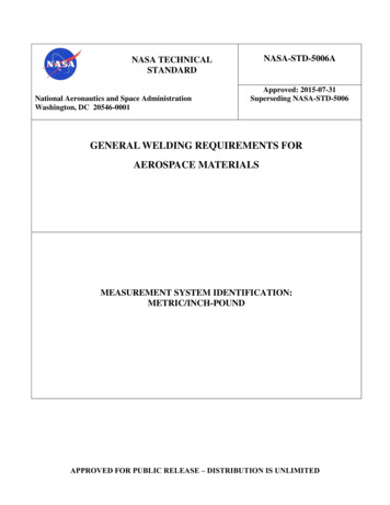
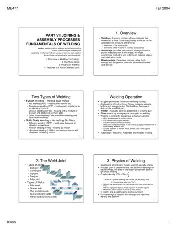
ME477Fall 2004Approximate Power Densities andEfficiencyPhysics of Welding II The estimated quantity of heat:where K 3.33x10⁻⁶U m KTm2 Heat waste:– Heat transfer efficiency, f1, between heat source and surface Heat problem: Oxyfuel gas welding is inefficient while Arc weldingis relatively efficient.– Melting efficiency, f2 , due to the conduction of a work material Conduction problem: Al and Cu have low f2 Net Heat Available for Welding: H w f1 f 2 H Balance between energy input and energy for welding:H w U mV Rate Balance: HR U WVRwW/mm2Welding processmwhere WVR volume rate of metal welded10(6)Arc50(30)Resistance1,000(600)Laser beam9,000(5,000)Electron beam10,000(6,000)f1Arc Welding Process f1 f 2 HR U m AwV7(Btu/sec-in2)OxyfuelShield Metal Arc Welding0.9Gas Metal Arc Welding0.9Flux-cored Arc Welding0.9Submerged Arc Welding0.95Gas Tungsten Arc Welding0.784. Features of Fusion Welded JointWeldInterface Fusion zoneHAZUBMZA typical fusion weld joint consists of fusion zone, weldinterface, heat affected zone and unaffected base metalzone.Fusion zone: a mixture of filler metal and base metalmelted together homogeneously due to convection as incasting. Epitaxial grain growth (casting)Weld interface – a narrow boundary immediatelysolidified after melting.Heat Affected Zone (HAZ) – below melting butsubstantial microstructural change even though thesame chemical composition as base metal (heattreating) – usually degradation in mechanical propertiesUnaffected base metal zone (UBMZ) – high residualstressWELDING PROCESSESFusion welding – Heat & meltingArc WeldingResistance WeldingOxyfuel WeldingOther Fusion WeldingSolid-state welding – Heat and pressure, butno melting & no fillerWeld QualityWeldabilityDesign Consideration9101. Arc Welding (AW) A fusion welding where thecoalescence of the metals(base metals and filler) isachieved by the heat fromelectric arc. Productivity: Arc time Technical issuesArc Welding Process– Electrodes – consumable and nonShield Metal Arc Weldingconsumable electrodesGas Metal Arc Welding– Arc Shielding – To shield the arcFlux-cored Arc Weldingfrom the surrounding gas. HeliumSubmerged Arc Weldingand argon are typically used. Fluxdoes a similar function.Gas Tungsten Arc Welding– Power source – dc for all metals orH w f1 f 2 H U mVac for typically steels Heat loss due to convection,conduction and radiationAW with Consumable Electrodes Shielded Metal Arc Welding (SMAW)– A consumable electrode – a filler metal rodcoated with chemicals for flux and shielding(230-460mm long and 2.5-9.4mm indiameter)– The filler metal must be comparable withbase metals.– Current: 30-300A and Voltage: 15-45V– Cheaper and portable than oxyfuel welding– Less efficient and variation in current due tothe change in length of consumableelectrodes during the process.f10.90.9 0.9Gas Metal Arc Welding (GMAW)– Use a bare consumable electrode– Flooding the arc with a gas which dependson the metal– No slag build-up and higher deposition ratethan SMAW– Metal Inert Gas (MIG) or CO2 welding0.950.7where f1 is the heat efficiencyf 2 is the melting efficiencyH is the total heat generated1112V is the metal volume meltedKwon2
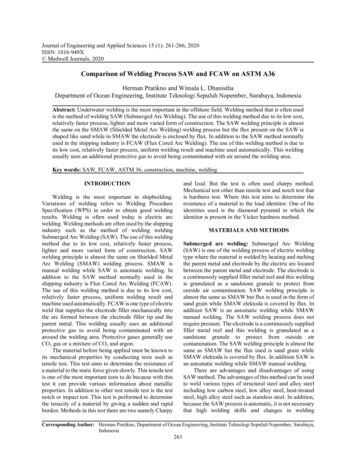
ME477Fall 2004AW with Consumable Electrodes Flux-cored Arc Welding (FCAW)AW with non-consumable Electrodes – Use a continuous consumable tubewith flux and others such as deoxidizerand alloying elements– Two typesGas Tungsten Arc Welding (GTAW)–––––Tungsten (Wolfram) Inert Gas (TIG) WeldingWith or without a filler metalTungsten melts at 3410 CShielding gas: argon, helium or a mixtureAll metals (commonly Al and Stainless steels)in a wide range of thickness– Slow and costly but high quality weld for thinsections Self-shielded – flux has an ingredient forshielding Gas-shielded – external gas– Produce high quality weld joint Electrogas Welding (EGW)– Flux-cored or bare electrode withexternal shield gas and water-cooledmolding shoes.– Used in shipbuilding Plasma Arc Welding (PAW) – a special formof GTAW but with a constricted plasma gas toattain a higher temperatureCarbon Arc Welding – Graphite is used aselectrodeStud Welding – for cookware, heat radiationfin. Submerged Arc welding (SAW)– Shielding is provided by the granularflux– Large structures 13142. Resistance Welding Force RW – heat and pressure toaccomplish coalescence. Power source: heat generated: H I 2 Rt Resistance Welding Processes– Resistance spot welding (RSW)Spot Welding Cycle electrodeWeld nugget- electrodeForce Electrodes – Cu-based orrefractory(Cu W) Rocker-arm spot welders(1) Upset welding – similar to FW but pressedduring heating and upsetting. Percussion welding – similar to FW butshorter duration– High-frequency (induction and resistance)welding(2)Force, Current– Resistance seam welding (RSEW)– Resistance projection welding (RPW)– Flash welding (FW) – Heating me15164. Other Fusion Welding3. Oxyfueld gas Welding Oxyfuel gas weldings (OFW) – Usevarious fuels mixed with oxygen Oxyacetylene welding – A mixture ofacetylene and oxygen Electroslag Welding – similar to electrogas welding, no arc isusedThermit (from Thermite ) Welding, dated 1900, is a fusion –welding process that uses a mixture of Al powder and ironoxide in 1:3 ratio for exothermic reaction (reaching 2500 C)– Used in railroad, repair cracks in ingot and large frame and shaft.– Total heat: 55x106J/m3– Acetylene: odorless but commercialacetylene has a garlic order.– Unstable at 1atm thus dissolved inacetone. Other gases– MAPP (Dow), Hydrogen,Propylene, Propane and Natural gasKwonOuter Envelope(1260 C)Acetylene feather(2090 C)Inner cone17(3480 C)183
ME477Fall 2004High Energy beam Welding 5. Solid-State Welding No filler metals but w/o local melting with eitherpressure-alone or heat and pressure. Intimate contact is necessary by a through cleaningor other means. Solid-state Welding ProcessesElectron Beam Welding– A high-velocity, narrow-beam electron converting into heat toproduce a fusion weld in a vacuum (Multiple degrees of vacuum)– From foil to plate as thick as 150mm– Very small heat effected zonef EI– Power density PD A––––––Forge welding – Samurai swordCold welding – high pressureRoll weldingHot-pressure weldingDiffusion welding at 0.5TmExplosive welding – mechanical locking commonly used tobond two dissimilar metals, in particular to clad one metalon top of a base metal over large areas– Friction welding – friction to heat– Ultrasonic welding – oscillatory shear stresses of ultrasonic1 Laser Beam welding– A high-power laser beam as the source of heat to produce a fusionweld without a filler material– Due to the high density energy on a small focused area, narrow anddeep penetration capability– Pulsed beam for spot-weld thin samples– Continuous beam for deep weld and thick sample– e.g.: Gillette Sensor razor19Explosive, Friction & UltrasonicWelding20Comparison21226. Weld Quality Residual Stress and Distortion– Welding fixtures, Heat sink,Tack welding, control weld condition, Preheating,Stress-relief heat treatment, Proper design Welding Defects Visual Inspection – Most widely used welding inspection, Limitations:– Cracks, Cavities, Solid Inclusions, Incomplete Fusion– Imperfect shape, Miscellaneous Defects such as arc strike and excessive spatter.– dimensional, warpage, crack– Only surface defects are detectable– Internal defects cannot be discovered– Welding inspector must also determine if additional tests are warranted Nondestructive– dye- and fluorescent-penetrant - detecting small defects open to surface– Magnetic particle testing - iron filings sprinkled on surface reveal subsurfacedefects by distorting magnetic field– Ultrasonic - high frequency sound waves directed through specimen, sodiscontinuities detected by losses in sound transmission– Radiograph - x-rays or gamma radiation to provide photographic film record of anyinternal flaws Destructive – mechanical & metallurgical tests23Kwon244
ME477Fall 2004Mechanical Tests for Welding7. Weldability Similar to Machinability, it defines the capacity of a metalto be welded into a suitable design and the resultingweld joint to perform satisfactorily in the intendedservice. The factors affecting weldability, welding process, basemetal, filler metal and surface condition. Base metal – melting point, thermal conductivity andCTE Dissimilar or filler materials, Strength, CTE mismatchand compatibility must be considered. Moisture and oxide film affects porosity and fusionrespectively.25268. Design Considerations Design for welding Minimum parts Arc WeldingBRAZING SOLDERING ANDADHESIVE BONDING– Good fit-up of parts– Access room for welding– Flat welding is advised Spot welding––––1. Brazing2. Soldering3. Adhesive BondingLow carbon steel up to 3.2mmFor large components: reinforcing part or flangesAccess room for weldingOverlap is required27Introduction1. Brazing Brazing and soldering – A filler metal ismelted and distributed by capillary action butno melting of parent metals occurs. Brazing & soldering instead of fusion welding If properly designed and performed, solidified joint willbe stronger than filler metal. Why?– Small part clearances used in brazing– Metallurgical bonding that occurs between base and fillermetals– Geometric constrictions imposed on joint by base parts––––Join the metals with poor weldability.Join dissimilar metals.No heat damage on the surfaces.Geometry requirement is more relaxed thanwelding.– No high strength requirement Adhesive Bonding – similar to brazing andsoldering but adhesives instead of fillermetals.Kwon28 Applications–––––Automotive (e.g., joining tubes and pipes)Electrical equipment (e.g., joining wires and cables)Cutting tools (e.g., brazing cemented carbide inserts to shanks)Jewelry-makingChemical process industry, plumbing and heating contractorsjoin metal pipes and tubes by brazing– Repair and maintenance work29305
ME477Fall 2004Advantages and DisadvantageBrazed Joints Butt Advantages– Any metals can be joined– Certain methods are quickly and consistently orautomatically done– Multiple brazing at the same time– Very thin parts can be joined– No heat affected zone– Joints inaccessible by welding can be brazed Lap – a wider area for brazing metal Disadvantage– Strength,– Low service temperature,– Color mismatch with the color of base metal parts Lap joints take more load than butt joints.Brazed JointsJoint strength3132Common Filler Metals Clearance between mating surface for capillary clearanceaction (0.025 and 0.25mm) Cleanliness of the joint – chemical (solvent cleaning& vapor degreasing) and mechanical (wire brushing& sand blasting) treatments Fluxes are used during brazing to clean surfaces andto promote wetting Common filler metals– Compatible melting temperature compatible with base metal– Low surface tension for wetting– High fluidity, Strength and no chemical and physicalinteractions with base materialsFiller Metal TypicalCompositionBrazingTemp.( C)Base metalsAl & Si90Al, 10Si600AlCu99.9Cu1120Ni and CUCu & P95Cu, 5P850CuCu & Zn60Cu, 40Zn925Steels, Cast Ironand NiAu & Ag80Au, 20Ag950Stainless steeland Ni alloysNi alloysNi, Cr, others1120Stainless steeland Ni alloysSilver alloysAg, Cu, Zn, Cd730Ti, Monel, Inconel,Tool steel and Ni3334Brazing method2. Soldering Similar to Brazing but the filler material melts below450 C A filler material is solder and sometimes tinning (coatingthe faying surfaces) is needed. Typical clearance ranges from 0.076 to 0.127mm. After the process, the flux residue must be removed. Advantage Several techniques for applying filler metal Brazing fluxes– Avoids oxide layers or unwanted by-product– Low melting, low viscosity, wetting, protection until brazingmetals solidify– Borax, borates, fluorides and chlorides in a form of powder,paste or slurries– Low energy, variety of heating methods, good electrical andthermal conductivity, air-tight & liquid-tight seams and reparable Disadvantage– Low strength, weak in high temperature applications For mechanical joints, the sheets are bent and the wiresare twisted to increase joint strength. Brazing methods depending on heat source– Torch, Furnace, Induction, Resistance, Dip (either molten saltbath or molten metal bath), Infrared and brazing welding– Electronic applications: electrical connection.– Automotive application: vibration.35Kwon366
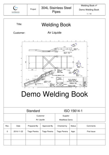
ME477Fall 2004Materials and Methods 3. Adhesive bonding The filler material is called adhesive (usually polymer)requiring curing sometime with heat. Strength depends on chemical bonding, physicalinteraction (secondary bonds) and mechanical locking. Surface preparationSolders – mainly alloys of tin and lead (low melting point) but in solderingcopper, intermetallic compounds of copper and tin and in soldering alloyssilver and antimony.Fluxes: Melt at soldering temperature, Remove oxide films, Prevent oxideformation, Promote wetting, Displaced by the molten solder– Types: Organic and inorganic – clean and rough surfacesMethods Application methods– Hand soldering – soldering gun– Wave soldering– Brushing, rollers, silk screen, flowing, splaying, roll coating Multiple lead wires on a printed circuit board(PCB) Advantage– a wide variety of materials, different sizes, bonding over an entiresurface and flexible adhesives, low temp. curing, sealing, simplejoint design Disadvantage– Reflow soldering – A solder paste consists of solder powders in a fluxbinder, which is heated either using vapor phase reflow or infraredreflow.37– weaker bonding, compatible, limited service temperature, curingtimes and no inspection method38Adhesive typesJoint Design Natural adhesives - derived from natural sources,including gums, starch, dextrin, soy flour, collagen Adhesive joints are not as strong as welded, brazed, or soldered joints Joint contact area should be maximized Adhesive joints are strongest in shear and tension Joints should be designed so applied stresses are of these types Adhesive bonded joints are weakest in cleavage or peeling Joints should be designed to avoid these types of stresses– Low-stress applications: cardboard cartons, furniture,bookbinding; or large areas: plywood Inorganic - based principally on sodium silicate andmagnesium oxychloride– Low cost, low strengthTension Synthetic adhesives - various thermoplastic andthermosetting polymersShearcleavagepeeling– Most important category in manufacturing– Synthetic adhesives cured by various mechanisms, such asMixing catalyst or reactive ingredient with polymer prior toapplying, Heating to initiate chemical reaction, Radiation curing,such as ultraviolet light, evaporation of water from liquid or paste,Application as films or pressure-sensitive coatings on surface ofone of adherents39Kwon407
Welding process W/mm2 (Btu/sec-in2) Gas Tungsten Arc Welding 0.7 Submerged Arc Welding 0.95 Flux-cored Arc Welding 0.9 Gas Metal Arc Welding 0.9 Shield Metal Arc Welding 0.9 Arc Welding Process f 1 9 4. Features of Fusion Welded Joint A typical fusion weld joint consists of fusion zone, weld interface, heat affected zone and unaffected base .