Transcription
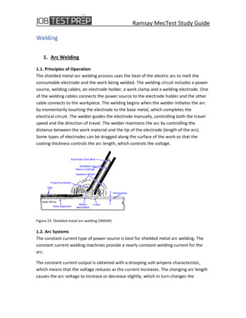
Ramsay MecTest Study GuideWelding1. Arc Welding1.1. Principles of OperationThe shielded metal arc welding process uses the heat of the electric arc to melt theconsumable electrode and the work being welded. The welding circuit includes a powersource, welding cables, an electrode holder, a work clamp and a welding electrode. Oneof the welding cables connects the power source to the electrode holder and the othercable connects to the workpiece. The welding begins when the welder initiates the arcby momentarily touching the electrode to the base metal, which completes theelectrical circuit. The welder guides the electrode manually, controlling both the travelspeed and the direction of travel. The welder maintains the arc by controlling thedistance between the work material and the tip of the electrode (length of the arc).Some types of electrodes can be dragged along the surface of the work so that thecoating thickness controls the arc length, which controls the voltage.Figure 23. Shielded metal arc welding (SMAW)1.2. Arc SystemsThe constant current type of power source is best for shielded metal arc welding. Theconstant current welding machines provide a nearly constant welding current for thearc.The constant current output is obtained with a drooping volt-ampere characteristic,which means that the voltage reduces as the current increases. The changing arc lengthcauses the arc voltage to increase or decrease slightly, which in turn changes the
Ramsay MecTest Study Guidewelding current. Within the welding range, the steeper the slope of the volt-amperecurve, the smaller the current change for a given change in the arc voltage.1.2.1. Electrical TermsMany terms are associated with arc welding. The following basic terms are especiallyimportant.Alternating current — Alternating current is an electrical current that has alternatingnegative and positive values. In the first half-cycle, the current flows in one directionand then reverses itself for the next half-cycle. In one complete cycle, the currentspends 50 percent of the time flowing one way and the other 50 percent flowing theother way. The rate of change in direction is called frequency, and it is indicated bycycles per second. In the United States, the alternating current is set at 60 cycles persecond.Ampere — Amperes, sometimes called “amps,” refers to the amount of current thatflows through a circuit. It is measured by an “amp” meter.Conductor — Conductor means any material that allows the passage of an electricalcurrent.Current — Current is the movement or flow of an electrical charge through a conductor.Direct current — Direct current is an electrical current that flows in one direction only.Electrical circuit — Electrical circuit is the path taken by an electrical current flowingthrough a conductor from one terminal of the source to the load and returning to theother terminal of the source.Polarity — Polarity is the direction of the flow of current in a circuit. Since current flowsin one direction only in a DC welder, the polarity becomes an important factor inwelding operations.Resistance — Resistance is the opposition of the conductor to the flow of current.Resistance causes electrical energy to be changed into heat.Volt — A volt is the force which is required to create the current flow in an electricalcircuit. It can be compared to pressure in a hydraulic system. Volts are measured with avoltmeter.
Ramsay MecTest Study GuideMetal TransferThe intense heat of the welding arc melts the tip of the electrode and melts the surfaceof the base metal. The temperature of the arc is about 9000 F (5000 C) which causesalmost instantaneous melting of the surface of the work. Globules form on the tip of theelectrode and transfer through the arc to the molten weld puddle on the surface of thework. When the detaching globules are small during the transfer, this is known as “spraytype metal transfer”. When the globules are relatively large during transfer, it is knownas globular type metal transfer. Surface tension sometimes causes a globule of metal toconnect the tip of the electrode to the weld puddle, causing an electrical short andmaking the arc go out. Usually, this is a momentary occurrence, but occasionally theelectrode will stick to the weld puddle. When the short circuit occurs, the current buildsup to a short circuit value and the increased current usually melts the connecting metaland reestablishes the arc.1.3. The Basic Equipment for WeldingThe equipment for the shielded metal arc welding process consists of a power source,welding cable, electrode holder, and work clamp or attachment. Figure 24 shows adiagram of the equipment.
Ramsay MecTest Study GuideFigure 24. Equipment for shielded metal arc welding.1.3.1. Power SourcesThe purpose of the power source or welding machine is to provide the electric power ofthe proper current and voltage to maintain a welding arc. Many different sizes and typesof power sources are designed for shielded metal arc welding. Most power sourcesoperate on 230-volt or 460-volt input electric power, but power sources that operate on200 or 575-volt input power are also available.1.3.2. Types of CurrentShielded metal arc welding can use either direct current (DC) or alternating current (AC).Electrode negative (straight polarity) or electrode positive (reverse polarity) can be usedwith direct current. Each type of current has distinct advantages, but the selection ofthe type of welding current used usually depends on the availability of equipment andthe type of electrode which is selected. Direct current flows in one directioncontinuously through the welding circuit. The advantage it has over alternating currentis that direct current is better at low currents and with small-diameter electrodes.
Ramsay MecTest Study GuideAll classes of covered electrodes can produce satisfactory results. Arc starting isgenerally easier with direct current.Maintaining a short arc is easier. Direct current is easier to use for out-of-positionwelding because lower currents can be used.Direct current is easier to use for welding sheet metal. It generally produces less weldspatter than alternating current.Polarity or direction of current flow is important in the use of direct current. Electrodenegative (straight polarity) is often used when shallower penetration is required.Electrode positive (reverse polarity) is generally used where deep penetration is needed.Normally, a negative electrode negative provides higher deposition rates than electrodepositive. The type of electrode often governs the polarity to be used.1.3.3. Power Source Duty CycleDuty cycle is the ratio of arc time to total time. For a welding machine, a 10-minute timeperiod is used. Thus, for a 60% duty cycle machine, the welding load would be appliedcontinuously for 6 minutes and would be off for 4 minutes. Most industrial typeconstant current machines are rated at 60% duty cycle. The formula for determining theduty cycle of a welding machine for a given load current is:(𝑅𝑎𝑡𝑒𝑑 𝐶𝑢𝑟𝑟𝑒𝑛𝑡)2%𝐷𝑢𝑡𝑦 𝐶𝑦𝑐𝑙𝑒 %𝑅𝑎𝑡𝑒𝑑 𝐷𝑢𝑡𝑦 𝐶𝑦𝑐𝑙𝑒(𝐿𝑜𝑎𝑑 𝐶𝑢𝑟𝑟𝑒𝑛𝑡)2For example, if a welding machine is rated at a 60% duty cycle at 300 amperes, the dutycycle of the machine when operated at 350 amperes would be:%𝐷𝑢𝑡𝑦 𝐶𝑦𝑐𝑙𝑒 (300)2 60% 44%(350)21.3.4. Selecting a Power SourceSelecting a welding machine is based on: The amount of current required for the work.The power available to the job site.Convenience and economic factors.The size of the machine is based on the welding current and duty cycle required.Welding current, duty cycle, and voltage are determined by considering weldjoints, weld sizes, and welding procedures. The incoming power available
Ramsay MecTest Study Guide dictates this fact. Finally, the job situation, personal preference, and economicconsiderations narrow the field to the final selection. Consult with the localwelding equipment supplier to help make your selection. Be knowledgeable ofthe following data when selecting a welding power source:Rated load amperes (current)Duty cycleVoltage of power supply (incoming)Frequency of power supply (incoming)Number of phases of power supply (incoming)Figure 25. Arc welding setup1.3.5. ControlsThe controls are usually located on the front panel of the welding machine. Theseusually consist of a knob or tap switch to set the rough current range and a knob toadjust the current within the set range. On DC welding machines there is usually aswitch to change polarity, and on combination AC-DC machines, there is usually a switchto select the polarity or AC current. An On-Off switch is also located on the front of themachine. Arc Force Control is a function of amperage triggered by a preset (internalmodule) voltage. The preset trigger voltage is 18 volts. What this means is that anytimethe arc voltage drops from normal welding voltage to 18 volts or less, the drop triggersthe arc force current, which gives the arc a surge of current to keep the arc from goingout. When an arc is struck, the electrode is scratched against the work. At that point,the voltage goes to -0- which triggers the arc force current and the arc is initiatedquickly.On a standard machine without arc force control, arc striking is difficult and electrodesticking may occur. After the arc is established, a steady burn-off is desired. As theelectrode burns and droplets of metal are transferred from the end of the electrode tothe workpiece, there is a time period when the droplet is still connected to the end ofthe electrode but is also touching the workpiece. When this occurs, the machine is, in
Ramsay MecTest Study Guideeffect, in a "dead-short. The voltage drops, the arc force is triggered, and the droplet istransferred. On machines without arc force, the burn-off is the same; however, withoutthe arc force to help, an arc outage may occur, and the electrode will stick in the puddle.In tight joints, such as pipe welding, the arc length is very short and with standardmachines, it is difficult to maintain the arc since it wants to "short-out" against thesidewalls or bottom of the joint. The arc force control can be adjusted on this typeapplication to prevent electrode sticking; whenever the voltage drops, the drop triggersthe arc force current and the sticking doesn't happen because the current surge occurs.1.3.6. Electrode HolderAn electrode holder, commonly called a stinger, is a clamping device for holding theelectrode securely in any position. The welding cable attaches to the holder through thehollow insulated handle. The design of the electrode holder permits quick and easyelectrode exchange. Two general types of electrode holders are in use: insulated andnon-insulated . The non-insulated holders are not recommended because they aresubject to accidental short-circuiting if they bump against the workpiece during welding.For safety reasons, try to ensure that only insulated stingers are used on the job site.1.3.7. Welding CablesThe welding cables and connectors connect the power source to the electrode holderand to the work. These cables are normally made of copper or aluminum. The cable thatconnects the work to the power source is called the work lead. The work leads areusually connected to the work by pincher clamps or a bolt. The cable that connects theelectrode holder to the power source is called the electrode lead. The welding cablesmust be flexible, durable, well insulated, and large enough to carry the required current.Use only cable specifically designed for welding, and always use a highly flexible cablefor the electrode holder connection. This is necessary so the operator can easilymaneuver the electrode holder during the welding process. The work lead cable neednot be so flexible because once it is connected, it does not move. Two factors determinethe size of the welding cable to use: the amperage rating of the machine and thedistance between the work and the machine. If either amperage or distance increases,the cable size must also increase. Cable sizes range from the smallest at AWG No.8 toAWG No. 4/0 with amperage ratings of 75 amperes and upward. Table 8-1 showsrecommended cable sizes for use with different welding currents and cable lengths. Thebest size cable is one that meets the amperage demand but is small enough tomanipulate easily. As a rule, the cable between the machine and the work should be as
Ramsay MecTest Study Guideshort as possible. Use one continuous length of cable if the distance is less than 35 feet.If you must use more than one length of cable, join the sections with insulated lock-typecable connectors. Joints in the cable should be at least 10 feet away from the operator.1.3.8. Welding ElectrodesWhen a piece of metal is heated in the atmosphere it combines with the oxygen andnitrogen to form oxides and nitrides which combine with the metal. If these wereallowed to form in the weld it would result in a poor quality, weak and brittle weld. It is,therefore, necessary to protect the weld area from the air. This can be done either bysurrounding the weld area by an inert gas or via the use of suitable fluxes. It is commonwith manual metal arc welding to use coated electrodes, for example. These electrodesconsist of a metal core surrounded by a layer of suitable flux coating.1.3.8.1. Covered electrodesThe covered electrode provides both the filler metal and the shielding for the shieldedmetal arc welding process. Covered electrodes have different compositions of the corewire and a wide variety of types of flux coverings that perform one or all of the followingfunctions, depending upon the type of electrode:1. Forming a slag blanket over the molten puddle and solidified weld2. Providing shielding gas to prevent atmospheric contamination of both the arc streamand the weld metal3. Providing ionizing elements for smoother arc operation4. Provides deoxidizers and scavengers to refine the grain structure of the weld metal5. Providing alloying elements such as nickel and chromium for stainless steel6. Providing metal such as iron powder for higher deposition rates1.3.8.2. Functions of the Electrode CoatingThe six main functions of the electrode coating are as follows:1. To act as a flux and remove the impurities from the surfaces being welded.
Ramsay MecTest Study Guide2. To form a protection layer (slag) over the weld, which prevents contact with the air asit starts to cool down. This prevents the weld from becoming brittle and provides asmoother surface by preventing ripples caused during the welding process.3. It forms a neutral gas atmosphere, which helps to protect the molten weld pool fromoxygen and nitrogen in the surrounding air.4. It helps to stabilize the arc, allowing Alternating Current (AC) to be used.5. It can add certain constituents to the weld by replacing any that are lost during thewelding process.6. It can speed up the welding process by increasing the speed of melting the metal andthe electrode.The first two functions listed prevent the pickup of nitrogen and oxygen into the weldpuddle and the red-hot solidified weld metal. The nitrogen and oxygen form nitrides andoxides which cause the weld metal to become brittle.1.3.8.3. Electrodes ClassificationThe classification system for covered electrodes used throughout the industry in theUnited States was devised by the American Welding Society. In this system, designationsfor covered electrodes consist of the letter E (for electrode) and four (or five) digits forcarbon steel and low-alloy steel covered electrodes. Sometimes a suffix appears on theend as well. These digits have specific meanings, which are:1. The first two (or three) digits indicate the minimum tensile strength in 1,000 psi, ofthe weld metal deposited. Figure 26 lists the different digits used.2. The third (or fourth) digit indicates the welding positions in which the electrode canbe used. Table 8-3 lists the use of the different digits.3. The fourth (or fifth) digit indicates the current characteristics and the types ofelectrode coating.Table 8-4 describes what the different digits indicate.4. A suffix is sometimes added to the EXXXX designation (it does not apply to the E60XXclassification). The suffix indicates the chemical composition of the deposited weldmetal.
Ramsay MecTest Study GuideFigure 26. Electrode classification2. Air Carbon-Arc CuttingAir carbon-arc cutting (ACC) is a process of cutting, piercing, or gouging metal by heatingit to a molten state and then using compressed air to blow away the molten metal. Theequipment consists of a special holder that uses carbon or graphite electrodes andcompressed air fed through jets built into the electrode holder. A push button or a handvalve on the electrode holder controls the air jet. The air jet blows the molten metal
Ramsay MecTest Study Guideaway and usually leaves a surface that needs no further preparation for welding. Theelectrode holder operates at air pressures between 60 and 100 psi.3. Gas WeldingOxy-fuel welding, commonly referred to as oxy welding or gas welding, is a process ofjoining metals by application of heat created by a gas flame. The gas is commonlyacetylene, which when mixed with a proper proportion of oxygen in a mixing chamberwith a welding torch, produces a very hot flame of about 5700-5800 F. With this flame,it is possible to bring any of the so-called commercial metals, namely: cast iron, steel,copper, and aluminum, to a molten state and cause a fusion of two pieces of like metalsin such a manner that the point of fusion will very closely approach the strength of themetal fused. If more metal of a like nature is added, the union is made even strongerthan the original. This process is called oxy-acetylene welding.Cutting with the oxy-fuel process is essentially just the opposite form of welding. Oxyfuel cutting uses acetylene and oxygen to preheat metal to red hot and then uses pureoxygen to burn away the preheated metal. Because this is achieved by oxidation, it isonly effective on metals that are easily oxidized at this temperature. Such metals aremild steel and low allow steels. Oxy-fuel cutting can be used to cut thicknesses from2/8″ to up to 12″.Traditionally oxy-fuel processes are used for brazing, fusion welding, flame hardening,metalizing, soldering, stress relieving, cutting and bending. The primary uses today arewelding, brazing, and cutting. This course describes the basic concepts of oxy-fuelwelding and cutting including what equipment and safety precautions are needed.3.1. Oxy-Acetylene Apparatus
Ramsay MecTest Study GuideFigure 26. Equipment for Oxy-acytelene weldingThe basic equipment used to carry out gas welding and cutting is:1. Oxygen gas cylinder (green)2. Acetylene gas cylinder (maroon/red)3. Oxygen pressure regulator4. Acetylene pressure regulator5. Oxygen gas hose(Blue)6. Acetylene gas hose(Red)7. Welding torch or blowpipe with a set of nozzles and gas lighter8. Trolleys for the transportation of oxygen and acetylene cylinders9. Set of keys and spanners10. Filler rods and fluxes
Ramsay MecTest Study Guide11. Protective clothing for the welder (e.g. asbestos apron, gloves, goggles, etc.)3.1.1. Oxygen Gas CylinderAn oxygen cylinder is drawn from a piece of high-strength steel plate and is available incommon sizes of:1.- 244 cu ft (for industrial plants);2.-122 cu ft;3.- 80 cu ftOxygen is stored within cylinders at a pressure of 2200 psi when filled at 70 F and iscapable of retaining a pressure of almost twice the fill pressure.3.1.2.Acetylene Gas CylinderAn acetylene cylinder is also a solid drawn steel cylinder and the common sizes are 300,120, and 75 cubic feet. Cylinder pressure is 250 PSI when filled. An acetylene cylinder ispainted maroon and the valves are screwed left-handed (with a grooved hex on the nutor shank).Acetylene is extremely unstable in its pure form at a pressure above 15 PSI. Thisinstability places special requirements on the storage of acetylene. Acetylene cylindersare packed with porous materials (balsa wood, charcoal, corn pith, or Portland cement)which are saturated with acetone to allow the safe storage of acetylene. These porousfiller materials aid in the prevention of high-pressure gas pockets forming in thecylinder.Acetone, a colorless, flammable liquid, is then added to the cylinder until about 40percent of the porous material is saturated. Acetone is a liquid chemical that dissolveslarge portions of acetylene under pressure without changing the nature of the gas, andis a liquid capable of absorbing 25 times its own volume of acetylene gas at a normalpressure. Being a liquid, acetone can be drawn from an acetylene cylinder when it is notupright.3.1.3. Pressure RelationshipIn an oxygen cylinder, there is a precise relationship between cylinder pressure andcylinder contents. A standard oxygen cylinder that contains 244 cu-ft at 2200 psi at700 F will contain 122 cu-ft when the pressure has dropped to 1100 psi at 700 F. Incontrast, an acetylene cylinder will not be precisely half-full when its pressure drops tothat of half. Note that the changes in temperature affect the pressure in an acetylene
Ramsay MecTest Study Guidecylinder at a much faster rate than it affects the pressure in an oxygen cylinder. Thepressure in an oxygen cylinder will go up or down only about 4 percent for each 20degree change in temperature (F) from 70 deg. A full acetylene cylinder which has apressure of 250 psi at 700 F will have a pressure of 315 psi at 900 F and a pressure of190 psi at 500 F. You must always take temperature into account when estimating howmuch acetylene the cylinder contains.3.1.4. Safety Devices on Acetylene Cylinder and oxygen cylinderAn acetylene cylinder is protected by a number of fusible plugs which melt at 220 F(104 C). These plugs melt and release the pressure in case the cylinder is exposed toexcessive heat. Small cylinders (the 10 cu-ft. and 40 cu-ft. sizes) have one fusible metalchannel located in the cylinder valve. The large cylinders normally used in welding andcutting, with capacities ranging up to nearly 300 cubic feet of acetylene, have two tofour plugs, located in both the tops and bottoms of the cylinders. If a cylinder is exposedto a fire, one or more safety devices will melt and allow the acetylene and acetone toescape and burn gradually. If it did not have such a safety device, a full acetylenecylinder exposed to a fire would rupture and release its contents all at once, perhapsexplosively.a.- DO NOT adjust, alter, change, build, or do any experimental work on cylinders,regulators, torches, or any other gas equipment;b.-DO NOT lift cylinders by the caps or valves;c.-DO NOT transport the cylinders without the caps in place;d.- Cylinders must be stored in an upright position;e.- KEEP valves closed on empty cylinders;f.- MAKE sure that cylinders are regularly re-tested using hydrostatic testing (NDE) whilein service.3.1.5. Oxygen & Acetylene Pressure RegulatorsThe pressure of the gases obtained from cylinders is considerably higher than the gaspressure used to operate the welding torch. The purpose of using a gas pressureregulator is: to reduce the high pressure of the gas in the cylinder to a suitable working pressure,and
Ramsay MecTest Study Guide to produce a steady flow of gas under varying cylinder pressures.A pressure regulator is connected between the cylinder/generator and the hose leadingto the welding torch. The desired pressure at the welding torch may be somewhere upto 35 psig (psi gauge) for oxygen and 15 psig for acetylene.A pressure regulator is fitted with two pressure gauges. One indicates the gas pressurein the cylinder and the other displays the reduced pressure at which the gas is going out.Figure 27. Gas pressure regulator3.1.6. Gas Hoses & ClampsThe hoses used to make the connections between the torch and the regulators must bestrong, nonporous, light, and flexible enough to make torch movements easy. The mostcommon type of cutting and welding hose is the twin or double hose that consists of thefuel hose and the oxygen hose joined together side by side.Size is determined by the inside diameter, and the proper size to use depends on thetype of work for which it is intended. The hose used for light work has a 3/1 6 or 1/4inch inside diameter and one or two plies of fabric. For heavy-duty welding and cuttingoperations, use a hose with an inside diameter of 5/1 6 inches and three to five plies offabric. A single hose is available in the standard sizes as well as 1/2-, 3/4-, and 1-inchsizes. These larger sizes are for heavy-duty heating and for use on large cuttingmachines.
Ramsay MecTest Study GuideOxygen hoses are green in color and have right-handed thread. Acetylene hoses are redin color with left-handed thread. The nut on the acetylene connection has a notch thatruns around the center, distinguishing it from the nut on the oxygen connection. This isa safety precaution which prevents hoses from being hooked up the wrong way.3.1.7. Welding Torch & Blow PipeA welding torch mixes oxygen and acetylene in the desired proportions, burning themixture at the end of the tip and providing a means for moving and directing the flame.There are two types of welding torches, namely:a) High pressure (or equal pressure) typeb) Low pressure (or injector) typeHigh-pressure blowpipes or torches are used with (dissolved) acetylene stored incylinders at a pressure of 117 psi. Low-pressure blowpipes are used with acetyleneobtained from an acetylene generator at a pressure of 8 inch - head of water(approximately 0.3 psi).In a high-pressure blowtorch, both the oxygen and acetylene are fed at equal pressuresand the gases are mixed in a mixing chamber prior to being fed to the nozzle tip. Thehigh-pressure torch, also called the equal pressure torch, is most commonly usedbecause:a) it is lighter and simpler;b) it does not need an injector;c) in operation, it is less troublesome since it does not suffer from backfires to the sameextent.Figure 28. Welding torch
Ramsay MecTest Study GuideTo change the power of the welding torch, it is only necessary to change the nozzle tip(size) and increase or decrease the gas pressures accordingly.3.2. Oxy-Acetylene WeldingThe oxyacetylene welding process uses a combination of oxygen and acetylene gas toprovide a high-temperature flame. The high-temperature flame melts the metal faces ofthe work-pieces to be joined, causing them to flow together. A filler metal alloy isnormally added and is sometimes used to prevent oxidation while facilitating the unionof the metal.The amount of heat applied to the metal is a function of the welding tip size, the speedof travel, and the welding position. The flame size is determined by the welding tip sizeand the proper tip size is determined by the metal thickness and the joint design.Characteristics of the oxy-acetylene welding process include:a.-The use of dual oxygen and acetylene gases stored under pressure in steel cylinders;b.-Its ability to switch quickly to a cutting process, by changing the welding tip to acutting tip;c.-The high temperature the gas mixture attains ( 5800 F);d.- The use of regulators to control gas flow and reduce pressure on both the oxygenand acetylene tanks;e.- The use of double line rubber hoses to conduct the gas from the tanks to the torch;f.-Melting the materials to be welded together;g.-The ability to regulate temperature by adjusting gas flow.3.2.1. Types of Welding FlamesIn oxyacetylene welding, the flame is the most important tool; all the weldingequipment is simply there in order to maintain and control the flame. The flame mustbe of the proper size, shape, and condition in order to operate with maximumefficiency. Three distinct types of flames are possible in adjusting the proportions ofacetylene and oxygen:1. Neutral Flame (Acetylene oxygen in equal proportions)2. Oxidizing Flame (Excess of oxygen)3. Reducing Flame (Excess of acetylene)
Ramsay MecTest Study GuideNeutral FlameA neutral flame is produced when the ratio of oxygen to acetylene, in the mixtureleaving the torch, is almost exactly one-to-one. The temperature of the neutral flame isof the order of about 5900ºF.The tip of the inner flame is the hottest part of the flame and is approximately 5850ºF,while at the end of the outer sheath or envelope the temperature drops toapproximately 2300ºF. This variation within the flame permits some temperaturecontrol when making a weld. The position of the flame relative to the molten puddle canbe changed, and the heat is controlled in this manner.Carburizing or Reducing Flame:If the volume of oxygen supplied to the neutral flame is reduced, the resulting flame willbe a carburizing or reducing flame, i.e. rich in acetylene. A reducing flame can berecognized by acetylene feather which exists between the inner cone and the outerenvelope. The outer flame envelope is longer than that of the neutral flame and isusually much brighter in color.Figure 28. Carburizing flameCarburizing Flame (Excess acetylene with oxygen, 5700 F) Used for hard-facing andwelding white metal.It is used for welding with low alloy steel rods and for welding those metals, (e.g.nonferrous metals) that do not tend to absorb carbon. This flame is very well used forwelding high carbon steel.Oxidizing FlameThe oxidizing flame is the third possible flame adjustment. It occurs when the ratio ofoxygen to acetylene required for a neutral flame is changed in order to give an excess ofoxygen. This flame type is observed when welders add more oxygen to the neutralflame.Figure 29. Oxidizing flame
Ramsay MecTest Study GuideAn oxidizing flame is of limited use in welding. It is not used in the welding of steel. Aslightly oxidizing flame is helpful when welding:a.- Copper-based metalsb.-Zinc-based metals, andc.- a few types of ferrous metals, such as manganese steel and cast iron.3.2.2. Setting up an Oxyacetylene TorchBefore you begin a welding operation, make a thorough inspec
Ramsay MecTest Study Guide Welding 1. Arc Welding 1.1. Principles of Operation The shielded metal arc welding process uses the heat of the electric arc to melt the consumable electrode and the work being welded. The welding circuit includes a power source, welding cables, an electrode holder, a