Transcription
MANUAL
IntroductionThank you for purchasingIP Cameras.A IP Camera (including Storage IP Camera, WiFi/Storage IP Camera, IR Dome IP Camera, IRDay and Night Waterproof IP Camera, and High Speed Dome IP Camera, etc.) is an integrated networkvideo surveillance device. With high performance and low cost single chip SOC, it realizes audio andvideo collection, compression, and network transmission in one camera. Optimized H.264 videocompression algorithm assures clear and fluent image transmission. Its built-in web server allows usersto remotely control the camera through Internet Explorer browser. In addition, the central managementsoftware is used for convenient management of multiple IP Cameras. Therefore it is easy to build a largevideo surveillance system withIP Cameras (hereinafter the IP Camera).The IP Camera is for small business and home use, and all places which require remotevideo transmission and surveillance. It is easy to install and use.Please check all the following items have been included with your IP Camera. Contact your vendorif anything is missing.Item Check List:1IP Camera1 pc2WiFi Antenna (for those models with WiFi function)1 pc3DC12V Power Supply Adapter1 pc4CD with User Manual1pcNotes: The IP Cameras series include Storage IP camera, WiFi/Storage IP camera, IR Dome IPcamera, IR Day and Night waterproof IP camera, and High Speed Dome IP camera. The default administrator and user name of the IP Camera: adminThe default password: admin. The default Web Port: 802 / 45
The default Data Port: 4000Statement: The version of this manual may be different with it of your IP Camera. If you have anyproblem which is not answered in this manual, please contact your vendor or technicalsupport of our company. Technology Co., Ltd. reserves the right to update the manual without notice.3 / 45
Table of Content123.4.5.6.Product Overview. 51.1 Product Application . 51.2 Brief Introduction . 51.3 Product Features . 61.4 Technical Specifications. 71.5 System Requirement. 7Appearance and Installation . 92.1. Appearance. 92.2. The Ports of the IP or IPWiFi Camera. 92.3. Installation . 10IE Browser Setup . 133.1. Searching Device and Modify the Network Settings . 133.2. Check Connection . 153.3. Install ActiveX and Login . 16Operation Instruction . 204.1. Buttons’ Function . 204.2. IP Camera Setup . 204.3. Device. 214.4. Network . 214.5. User . 274.6. Audio & Video . 274.7. Video Overlay. 294.8. Motion Detection. 304.9. Digital Input . 314.10. Digital Output. 314.11. Storage. 324.12. Recording Options. 334.13. Scheduled Recording. 344.14. Terminal Settings. 344.15. Log Information . 354.16. Maintenance . 364.17. Local Settings . 37Appendix. 395.1. DDNS Settings . 395.2. Router Port Forwarding Settings . 40Troubleshooting . 424 / 45
1Product Overview1.1 Product ApplicationThe IP Camera is used for public locations surveillance, such as supermarkets, schools,factories, and warehouses etc. With its powerful image-processing capabilities, it also canbe used in places which require high resolution video surveillance, such as banks andtransportation management. Please see the picture below:1.2 Brief IntroductionThe IP Camera is a stand-alone web-server with network video surveillance application.With it, you can monitor the spot in real time from anywhere in the world through aninternet webpage browser or client software.The IP Camera is a low-cost video and audio remote transmission solution. It useshighly integrated chip to realize audio and video data collection, compression, and networktransmission on a single media process platform. By typing the IP address or the domainname of the IP Camera on a webpage browser, the remote user can monitor the real-timevideo and audio of the spot and talk to the persons at the spot through a computer. This IPcamera is for office or home use, and all places which require remote network videosurveillance and transmission. It is easy to install and use.You can set up 12 user accounts of the IP Camera simultaneously and fix the IP address5 / 45
range of each user to increase the network security.The IP Camera also has the motion detection function. It can send an email, takesnapshot, or record the video on the SD card in the camera if it detects a moving object.In addition, it has a set of multi-screen management software for Microsoft Windowssystem, so that the user can monitor maximum 36 channels video simultaneously on amonitor.1.3 Product Features High-density and programmable media processor Hi3512, single chip SOC, and high speed videocoprecessor. Support both high sensitivity CCD or progressive CMOS sensor H.264 Main Profile @ Level 2.2, which is easy to transmit high definition video data throughlimited network bandwidth Support up to 12 users simultaneously Built-in web server allows the use of standard IE browser for real-time monitor and management Support WiFi 802.11b/g wireless network Support SD card storage with maximum capacity 32G (please refer to specific models). Support remote system upgrade Support dynamic IP address, LAN, and Internet (ADSL and Cable Modem access) Support multiple network protocols: TCP/IP, UDP, SMTP, PPPoE, Dynamic DNS, DNSClient, SNTP, BOOTP, DHCP, FTP, SNMP , WIFI 802.11b/g Support two-way real-time audio talk-back Support motion detection function (area and sensitivity can be set) Support video shield/picture snap shot function Auto recovery if exception occurs and auto-connection if the internet is disconnected. Support dynamic alarm function to set alarm time6 / 45
1.4 Technical SpecificationsItemVideo CompressionData PortSpecificationsH.264 Main Profile @ Level 2.2CCD up to D1 (720 x 576 PAL, 720 x 480 NTSC)CMOS up to VGA (640 x 480)Brightness, Color, Contrast, Saturation, Hue, ImageQualityVideo Streaming or Audio & Video CompositeStreamingCCD:1-25 Frame/Second (PAL), 1–30 Frame/Second(NTSC), AdjustableCMOS: 1-25 Frame/Second, adjustable16Kbit /Second 4Mbit /Second1 Channel Microphone input1 Channel Linear OutputG.7261 10M/100M Self-adapting Ethernet PortPower InputMaximum PowerWorking TemperatureDC 12V 1ALess than 6W0-60 CWorking Humidity10 85%Operating System: Microsoft Windows 2000/2003/XPWeb Browser: Microsoft Internet Explorer 6.0 or aboveIEEE802.11b/g Wireless NetworkVideo ResolutionAdjustment of Video SettingsStreaming FormatVideo Frame RateVideo Compression Bit RateAudio Talk-backAudio OutputAudio CompressionSystem RequirementWiFi Module1.5 System Requirement¾Minimum Requirement CPU: Pentium 2.0Ghz Memory: 256MB Video Card: TNT2 Sound Card: Necessary for audio monitoring and two-way talking Hard Drive: To record video, minimum 40G¾Recommended System CPU: Pentium 2.6GMhz Memory: 512MB Video card: NVidia Geforce FX5200 or ATI RADEON 7000(9000) Series 128M7 / 45
Memory¾Operating System 32bit Windows2000/2003/XP/Vista and 64bit Windows2003/XP/Vista¾Software Requirement IE 6.0 or above DirectX8.0 or above TCP/IP protocol¾Other Requirement The PC video card must support color conversion and zoom in & out function. Thefollowing video cards are tested and recommended: NVidia TNT/TNT2, GeforceMx200/400/420/440, Fx5200/5600 series, ATI Radeon7000/7200/7500/8500/9000/9200/9500/9600 series, MatroxG450/550, and Intel 845G/865G series, etc. Please notethat the drive software of video card must support hardware zoom in & out function.8 / 45
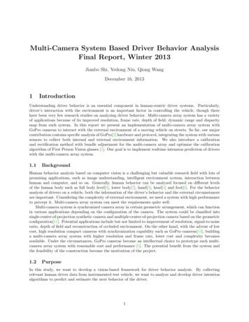
2Appearance and Installation2.1. Appearance2.2. The Ports of the IP or IPWiFi CameraBullet Camera:9 / 45
PT Camera:A outA inDC 12VANTRS485、GND、ALM in、ALM outRSTMicro SDLANLAN:Ethernet Network Card PortRST:Reset ButtonDC12V:DC 12V/1A Power SupplyA out:Audio OutputA in:Audio InputSD Card:SD card slotANT:WiFi Antenna PortALM out:Two Channels Alarm OutputALM in:One Channel Alarm InputGND:Signal ground, Alarm ground, RS485 groundRS485:RS485 Control Window. The left one is connected to negative pole of RS485 andthe right one is connected to the positive pole of RS485. It can be connected toPan/Tilt or encoder and can support multiple protocols2.3. InstallationThe IP Camera transmits image over the internet with current network technology. Itsupports dynamic DNS (Domain Name System) for users with dynamic IP and PPPoEthrough xDSL and PPPoE dial-up.For the two often used internet access methods: WEB verification and PPPoE dial-up,we can connect the IP Camera in the following three ways:10 / 45
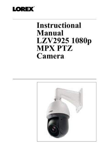
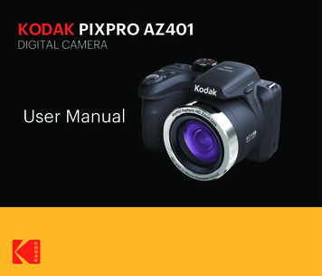
1.Connect an IP Camera to a router and access to the internet by a xDSL Modem:This is the often used internet access method. You can connect the IP Camera to a RJ45port of a router with a network cable. Then the IP Camera can access to the internet like aPC.2.Connect an IP Camera to a HUB and access to the internet by a xDSL Modem:The user should set the PPPoE dial-up as follows: input user name and passwordprovided by your ISP, and allow the IP Camera to dial up to access the internet.3.Connect an IP Camera to a Modem directly:Same as the second way, you should set up the PPPoE dial-up.11 / 45
Connect the IP Camera to the internet, or connect it with a PC with a network cabledirectly.After the IP Camera is connected to the internet, plug in the power of DC 12V, thenetwork connection light will be on in 5 seconds. Now, the physical connection of the IPCamera is finished.12 / 45
3. IE Browser Setup3.1. Searching Device and Modify the Network SettingsUse the DVS Search software to search the device and modify the network settings.Run DVS Search as follows:1.Find DVSImageCenter V1.2.7 in the tool software list of the enclosed CD and double click itto install into the computer.2.After the software is installed, find the DVS Search by Start All Programs DVSImageClient and click it to start.Notes: The firewall shall be shut off before DVS software searches the IP Camera.3.Click “Search” button to run DVS Search as follows:4.【Local IP address】 shows the local IP address of the connected device. If the current PChas multiple network cards or multiple local IP addresses, please select one IP address tosearch the IP Camera.The software will search the IP Camera in the network and display the result in the【Device Information Area】 The information includes the device name, model, channelnumber, IP Address, subnet mask, gateway, data port, web port, multicast IP, multicast port,DNS, MAC, and start DHCP.5.Select a device of IP Camera and click “Modify”, you will see the following picture:13 / 45
6.After the network settings are modified, click “OK” button, then the IP Camera will restartautomatically.Note: You can visit the IP Camera only when your PC and the IP Camera arein the same subnet. You may have to reset the IP address of the IP Camera.Check the IP address of the your PC: Start Run, type “command” or “cmd” (forWindows2000/XP, click “Confirm”).Then press the [Enter] key. Input “ipconfig” andpress [Enter], the network IP information will show up as follows:14 / 45
Now record the IP Address, Subnet Mask, and Default Gateway. Then set the IPaddress of the IP Camera in the same subnet of the user’s PC. Forexample:192.168.1.100. Please make sure the Default Gateway and Subnet Mask are assame as them of the PC.Notes:The default User Name: adminThe default Password: admin3.2. Check Connection1.The default IP address for the IP Camera is 192.168.0.250. The Subnet Mask is255.255.255.0. The DHCP function is turned on. Set the IP address of your PC in thesame subnet of IP Camera, which is explained in the above.2.Test the IP camera startup and connection: “Start” “Run” input “command” or “cmd” (forWindows 2000/XP). You will get the following window, then input “ping 192.168.1.5” andpress [Enter], you will see the following picture:15 / 45
Check the report and if you can ping through the IP Camera, that means the IP Cameraworks normally and connects to network correctly. If the screen displays other information thatyou cannot ping through, please double check the IP address settings and the cableconnections.3.3. Install ActiveX and LoginYou need to install ActiveX Control when you visit IP Camera for the first time through the IEbrowser. There are two ways to install ActiveX Control:1)Auto InstallationThe IE security settings must be downgraded temporarily so that the ActiveX component canbe installed on the PC. The installation steps are as follows:i.ii.Select Internet option in the tools menu of the IE browser;Click the “Security” tag and remember your default security settings;iii.Set the security level to “Low” and click “Apply”;iv.Input the web address of the IP Camera (such as abc.3322.org) in the IE browser addressbar or click the live show link to open the IE browser. A window will pop up askingwhether you would like to install ActiveX. Click “Yes” to start the installation;v.2)Reset the security settings to the default after the ActiveX installation is completed.Download Installation16 / 45
Visit the web address of the IP Camera, download the compressed package, decompress itinto a temporary folder, close all the IE web pages, then double click the install.bat file underthe decompressed folder and start to install as the following picture:The system will show that the installation is successful as the following pictureafter the installation is completed:17 / 45
Open the IE browser. Input the IP address of the IP Camera 192.168.1.5. Then thelogin window shows up as the following picture:Input the User Name (admin by default) and Password (admin in default), press“Enter” to enter into the main window as the following picture:18 / 45
Now the IP Camera is successfully installed and you can use it to monitor the spot.19 / 45
4. Operation Instruction4.1. Buttons’ Function: You can move up/down or left/right to control the direction of the IP【Pan Control】Camera.: Zoom in or out control.【Zoom Control】: Increase or reduce Aperture/Iris of the lens.【Iris Control】: Control focus of the lens.【Focus Control】: Open or close the light and brush.【Light and Brush】: Control the rotation speed.【PTZ Speed】: Click to start to record the image of spot. Double click to stop the【Video Record】recording. The image can be stored in the hard drive of the PC.【Playback】: Click, the viewer software will pop up. You can select the videoor picture to be played back.: Take snap shot of the spot and store the picture in the hard drive of【Snap Shot】the PC.: Choose the image size 1X, 2X or full screen of the【Video Size Zoom】IP Camera.: Flip or mirror the picture.【Flip and Mirror】【Setup】: Clickto setup the IP Camera. There are detailed instructions in thebelow.: Click【Audio Monitoring & Talk-back】of the spot through the PC. Clickso you can hear the soundto talk to the person at the spot.4.2. IP Camera SetupYou can login the IP Camera Setup window as the system administrator.20 / 45
When you click the【Setup】button, the following window will pop up:4.3. Device【Device Time】 You can set the time, or synchronize time with the PC. There are:1.Keep the current time;2.Synchronize with PC clock;3.Manually set the time;4.Synchronize with NTP server and select the proper time zone.【Device Information】System includes Device Name, Serial Number, Channel Count,Version, Build Date and Language.【Standard】Choose the video format.4.4. NetworkThe general Network Settings is as follows:21 / 45
Network SettingsExplanationIP AddressThe IP address of the IP CameraSubnet MaskSubnet Mask of the IP CameraGatewayThe gateway of the IP CameraDNS IP AddressDomain Name Server IP AddressData PortThe default data port of the IP Camera is 4000Web PortThe default WEB Port of the IP Camera is 80. If we set other numbersas the WEB Port, a complete IP address and port numbers are requiredto access to the web page of the IP Camera (For example, if the webport is 81, you need to input http://192.168.1.5:81 in order to access theweb page of the IP Camera)MAC AddressThe MAC Address of the IP CameraOther SettingsExplanationDDNSThe IP Camera supports the Dynamic Domain Name Service (DDNS)22 / 45
function. Please go to www.3322.org to register a free domain namebefore using this function, and then login with the registered user nameand password.With this setup the IP Camera is linked with a fixed Internet DomainName. No matter how the IP address of the IP Camera is changed, youcan visit the IP Camera through that domain name at any time.FTPPlease input the settings of FTP server, including the FTP serveraddress, the user name, and the password.EmailIt is to set the email server address and other information.Server URL: Input the SMTP address of your email server.User Name: Input the user name of your email account to send emails.Password: Input the password of your email account.From: Input the account name where the email is from.To: Input which email address you want to send the email.CC: Input which email address you want to send a copy of the email.23 / 45
P2PThis is to connect the IP Camera to the PC Point to Point. It issupported by our company’s P2P Server. For details please check thespecific modules.WiFiThis is to set the wireless connection between the IP Camera and thewireless router.24 / 45
If you want to use the wireless network, please click “Enable WIFI”first. And then set the IP address of wireless network to be the fixed IPaddress of internal network. Set up the wireless network correctly.Note: The IP address of the wireless IP Camera should be in differentsegment with the IP address of the wired IP Camera. Otherwise theymay affect each other and cannot be used properly.Modify the “General” settings of the IP Camera to comply with the wireless router’ssettings. We use D-Link DI-624 wireless router as an example:25 / 45
The left side is the settings of the wireless router. The WiFi settings must be the sameas it of the wireless router. And the wire IP address of the IP Camera should be in differentsubnet of the wireless router. For example, the network gateway of the wireless router is192.168.1.1. You can set the wire IP address of the IP Camera to be 192.168.55.1. Save thechange and unplug the power and network cable. Connect the USB wireless network card tothe IP Camera. Now the connection to the wireless router is ready.26 / 45
4.5. UserThe User Settings of the IP Camera are as follows:Each IP Camera can have maximum twelve user accounts simultaneously. One of themis the administrator; ten of them are the regular account and the other one is a guest account.Only the administrator account can set up the settings of the IP Camera.4.6. Audio & VideoThe Audio and Video Settings of the IP Camera are as follows:27 / 45
【Encode Settings】 The encode settings of video and audio:a)Stream No.Choose the stream (support only one stream currently)b) Image size:Four types of image size are available: D1, Half-D1, CIF, Q-CIFAccording to different network situation, we recommend the following settings:Applied Bandwidth and SettingsResolutionBandwidthc)Image Max bitrate: This is to set the image quality of the IP Camera. You can adjust itaccording to the internet speed 16000 - 8192000pbs.28 / 45
d) Bitrate type: Can choose CBR or VBR.e)Key frame interval: Choose from 1 to 100 frames.f)Image quality level: Choose from 0 to 5, only effective when choose VBR.【Image Settings】 The image parameter settings, there are:a)Brightnessb) Huec)Contrastd) Saturation【CMOS Settings】Only effective when the IP Camera has a CMOS sensor. It includes:a)Flip: To set the image upside down.b) Mirror: To exchange the left and right side of the image.c)Power line frequency: To Choose 50 or 60HZ of the electricity frequency.【Audio Settings】It can choose enable audio and audio input type: Line in or Microphone.4.7. Video OverlayThe Video Overlay Settings are as follows:【OSD】It is to add the character on top of the image, the contents are as follows:29 / 45
a)Show Date/Timeb) Show Bitratec)Show Title【Logo Settings】It is to add a picture (BMP format only with maximum pixel 96 x 96) on top ofthe image.【Video Cover】It is to set the covered area on the image with position and size ;4.8. Motion DetectionThe Motion Detection Settings are as follows:【Motion Detection】 It is to set the time of detection.【Detect Area】It is to test the specified detect area in the image. Left click and drag themouse to draw the detect area.a)Sensitivity: This is to set the high/low sensitivity of the motion detection area.b) Show Grids: To show the grids of the image.【Trigger Output Alarm】 It is to set whether to trigger the alarm equipment when the IPCamera detects a moving object.【Send Snapshots to】 It is to set where the snapshot image is sent and how long the30 / 45
interval between two snapshots is.【Corresponding Recording】 It is to save the record in the SC card and set the recordduration time.4.9. Digital InputThe Digital Input Settings are as follows:【Alert Time of Digital Input】It is to set the working time of the detector.【Trigger Output Alarm】It is to output alarm when the alarm is triggered.【Send Snapshots to】 It is to set where the snapshot image is sent and how long theinterval is between two snapshots.【Corresponding Recording】 It is to save the record in the SC card and set the recordduration time.4.10. Digital OutputThe Digital Output Settings are as follows:31 / 45
It is to set the alert time of digital input (arming time) and alarm detector test on/off.4.11. StorageThe Disk Settings are as follows:32 / 45
The disk of the IP Camera is the Micro SD card, which can be formatted by the settings.4.12. Recording OptionsThe Record Settings are as follows:33 / 45
【Recording Settings】It is to set whether to delete old files or stop record while the diskdoes not have enough space. You can also choose whether to record audio (only effectivewhen Encode Audio is clicked in the Video Settings).【Manual Recording】 It is to manually start/stop record. The default record time is 5minutes.4.13. Scheduled RecordingThe Schedule Record Settings are as follows:The IP Camera will start/stop record according to the time schedule and save the fileson the Micro SD card.4.14. Terminal SettingsThe Terminal Settings are as follows:34 / 45
It is to set the serial ports parameters of the IP Camera and to download the PT protocols tothe IP Camera, and to set the address for each channel corresponding with the PT decoder.The downloaded PT protocols are called the built-in protocols. We should set proper baudrate and data bit of RS485 serial port when using this built-in protocol.If we use RS232 serial port, similarly we need to set proper baud rate and data bit of it.4.15. Log InformationThe Alarm Message Settings are as follows:35 / 45
The settings include Alarm Type, Alarm Server, Alarm Channel, and Alarm time.4.16. MaintenanceIt is to maintain the IP Camera, including the reboot, restore and upgrade.36 / 45
【Reboot】IP CAMERA will reboot by clicking this button.【Restore】To restore the parameters to the default settings except the IP address;【Upgrade】To choose the file to upgrade;4.17. Local SettingsThe PC Parameters Settings are as follows:【 Disk Settings 】 To choose one or more disk partitions and the video files on PC will bekept in the chosen disk directory.【Recorder File Size】To set the maximum length of each video file. It will automaticallygenerate a new video file when the size exceeds the set length in the following two ways:a)Time limit : The time of each video file should not exceed the set length.b)Size limit : The bytes of each file should not exceed the set size.Note: Since it will generate a new video file when the key frame is received, there willbe a slight deviation in the video file size limitation.【 Clear Alarm 】 To set whether clear alarm and the alarm time automatically. When thealarm was not triggered in the stated time, it will clear the alarm status automatically. Agreen light will flash in the preview window to show the alarm status.37 / 45
【 Frame buffer 】 To set the frame buffer when we watch the video at the PC client end.The smaller the value, the less delay of video streaming. The larger the value, the moredelay of the video streaming. But the image will be more smooth.38 / 45
5. Appendix5.1. DDNS SettingsTo use www.3322.org DDNS as an example:On the webpage of www.3322.org, input your registered user name and password. Click“Manager Host” as follows:After entering the “Manager Host” page, click “Dynamic DNS” on the left side. Amenu will popup.Click “New” and input the secondary domain name which you want to create. Leaveother settings unchanged. Then click “OK”, the domain name will become effectiveimmediately as follows:39 / 45
Input the Registered domain name of the DDNS setup window of the IP Camera as follows:5.2. Router Port Forwarding SettingsTo remotely visit the IP Camera through router on Internet, the Web Port 80 and the Data Port4000 on the router should be opened. The port 80 is for visit with Web Browser, and port 4000 isfor transmit compressed video and audio data.Usually, Port Forwarding settings are in the Virtual Server option. You should set theforwarding to the LAN IP address of the IP Camera. We use D-Link DI-624 wireless router asan example:40 / 45
41 / 45
6. Troubleshooting1.Forget the pa
port of a router with a network cable. Then the IP Camera can access to the internet like a PC. 2. Connect an IP Camera to a HUB and access to the internet by a xDSL Modem: The user should set the PPPoE dial-up as follows: input user name and password provided by your ISP, and allow the IP Camera to dial up to access the internet. 3.