Transcription
Professional Central Monitoring SoftwareCMS ProFull-featured Enterprise Class Surveillance SolutionUser s ManualMADE IN KOREAM11131CMSProDRThis document contains preliminary information and is subject to change without notice.v1.09
Table of Contents1.6.2FEATURES.3Exit . 231.1Introduction .37.1.2Features .37.11.3System Requirements.37.2Live Monitor Menu. 247.2.1Full Screen On . 247.2.2Instant Playback . 257.2.3PTZ Control . 257.2.4Screen Capture & Print . 267.2.5Audio On/Off. 277.2.6Mike On/Off . 287.2.7Display Option . 282.2.1INSTALLATION.4Software Installation.42.2Login .52.2.1Login Process .53.MENU.74.SETUP .84.1Local Setup - Device .84.1.1Remote Site Connection Setup.84.1.1.1.New Device Register .84.1.1.2.Edit Registered Site .94.1.1.3.Remove Registered Site .94.1.2Device Group Setup.94.1.2.1.New Grouping Setting.104.1.2.2.Edit Group Setting.104.1.2.3.Remove Group Setting .105.Server List .185.2Remote Device System Log.185.3Remote Device Event Log .185.4CMS System Log .205.5Health Check.205.6Show All Windows.226.6.1Screen Layout Control. 287.4Change Division Display . 297.5Audio Volume Control . 29SEARCH . 308.1Overview . 308.2Time Bar Search . 308.3Event Search. 318.4POS/ATM Search. 328.5Thumbnail Search . 328.6Smart Search . 339.9.1E-MAP . 34Overview . 349.2Controls . 349.2.1E-map Camera – Instant Playback. 349.2.2Alarm In/Out Control. 359.2.3Audio . 3510. UNINSTALLING CMS PRO . 36VIEW .185.1Overview . 247.38.4.2Local Setup - Environment.104.2.1System .104.2.2Viewer .114.2.2.1.Audio.114.2.2.2.Video Display .114.2.3Record .114.2.4Setup.124.2.5Instant Playback.124.3Local Setup - Account .134.3.1Add User Account .134.3.2Edit User Account .144.3.3Remove User Account .144.3.4Login Setting .144.4Local Setup – E-map .144.4.1Registering a New E-map .144.4.2Remote Device Setup .164.4.3Change Password.174.5Help.174.5.1About.17LIVE (LIVE VIDEO MONITORING SYSTEM). 24APPLICATION.23Search.232
1. Features1.1 Introduction The CMS Pro is a central surveillance system solution that monitors multiple sites with video, audio and event signalsfrom DVR over networks. The software supports different windows of live viewer, playback player, interactive map viewer, various search panesand event signal monitoring panes.1.2 Features This program does not limit the number of units to register and monitor. The program displays up to 512 live videos; up to256 channels on one screen and 256 channels on the other screen. The program supports as many monitors as a PCsupports. Users may open windows or panes of live video displaying, data playing, event signal monitoring, map displaying,etc. Users can compose the central management system by choosing required widows or panes. The software supports different windows of live viewer, interactive map viewer, and event signal monitoring panes. The program displays event signals in real-time by receiving from devices over the network. On the program, users may control PTZ cameras and relay outputs on the server or DVR. By attaching microphone andspeaker system to devices on site, users may make bi-directional audio communication over the network. The main Search window provides users with various ways of searching data on DVR. The map supports multi-layer structure, so that each map on different layers can respond interactively. On the map, usersmay lay out icons of each device. Event signal triggers the icons on the map to blink, so that users may monitor eventsignals on the map. And Users can check the live view of individual camera on the map by clicking the video icon. With 5 different types of search function, users can search the recorded data according to user’s needs.1.3 System Requirements CMS Pro may not run properly if the PC does not meet minimum requirements. Other programs should not run on the samePC where this is running. Otherwise, CMS Pro software may not perform as designed.MinimumRecommendedDual Core 2.0GHzQuad Core 2.5GHz or higherMain Memory1GB2GB or higherVideo Memory512B1GB or higherCPUDisplay Resolution1024ⅹ768 (with 32bit color) or higherHDD Storage Space160GB or higherNetworkOperating SystemOthers100 1000 Mbps Fast EthernetWindows XP Professional SP3 / Windows 7 Home edition(32/64) / Windows 7 ultimate K(32/64)DirectX 9.0 C or higher3
2. Installation2.1 Software Installation Please follow the program installation procedures below.① If an old version of CMS Pro program was installed, completely uninstall or delete the old version.CAUTIONUSERS SHOULD COMPLETELY REMOVE CMS PRO PROGRAM OF AN OLD VERSION BEFORE INSTALLING NEW VERSION INORDER TO REDUCE COLLISION.② Insert the provided CD in a PC.③ Run the CMS Pro Setup.exe file.④ When the following screen appears, click “Next.”⑤ When the following screen appears, select folder and click “Next.”⑥ When the following screen appears, select the check box according to user’s preference and click “Next.”⑦ When the following screen appears, click “Install.”4
⑧ When the following screen appears, click “Finish” to complete the installation.CAUTION If the PC has a previously installed CMS Pro, the installer asks whether to overwrite the existing DB or not. The DBcontains setting values on the program. If desired to maintain the existing values, click ‘No’ button. If the Os is Windows 7, then users have to run the program as “Run as an administrator.” Or you can change the property of the program from the menu, properties(right mouse click on the CMS pro icon) Compatibility check “ Run this program as an administrator”2.2 Login2.2.1Login Process Open the CMS Pro. Users may open it by selecting the execution file through ‘Start’ menu [Start] – [CMS Pro] or by doubleclicking the execution icon on the background. Select a user ID in the ‘Login’ window. Users may see the entire list of IDs that are registered into the program by clicking onthe drop-down menu in the right-side. Initially, only the Administrator is registered as default. Enter the corresponding password with the selected ID. The default password of the ‘Administrator’ ID is ‘1111’.5
Administrator may change the password in the program.(NOTE)Users may change the password in [Setup] – [Change Password] menu. For the detailed information, please refer to the ‘4.4.3Change Password’ page.The CMS Pro archives settings and layouts on the program of the current user when the program is closed.6
3. Menu Below shows the brief explanation of each part on the screen.1Application2View set3Setup menu4Help menu5Server list pane6Display windows7Health check pane8Map list pane9Screen split selection icons10Audio control bar11Remote device system log pane12Remote device event log pane13CMS system log pane7
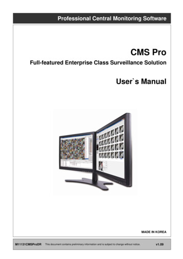
4. Setup4.1 Local Setup - Device Please make sure the network setting of DVR has been done properly prior to the remote connection setting.4.1.1Remote Site Connection Setup Click Setup – Local Setup – Device to enter the setup and a dialog will pop up as below picture.4.1.1.1. New Device RegisterDevice Select “Device Connection List” on left-hand side and click [New] to register new devices. Describe the connection information as below. User must fill in where information requested in bold.- Device Name: Type the DVR name to be displayed in the server list pane. Please note that this name has no relation tothe ID registered in DVR. Users may create a name to be easily distinguished.- Description: Type brief description of the site- IP Address: Input IP address or Domain Name of DVR (check from the SETUP DEVICES Network in DVR)- Command Port: Input Administrator’s number among port numbers set in DVR (check from theSETUP DEVICES Network in DVR). Default port number is 5920- Stream Port: Input Video/Audio number among port numbers set in DVR (check from the SETUP DEVICES Network inDVR). Default port number is 5921- Login ID: Type authorized ID of the DVR. Default ID is admin.- Login Password: Type correspond password of the ID. Default Password is 1111- Confirm Password: Retype the password to confirmCamera8
Choose a camera name between DVR and CMS setting or both.- By DVR setting: Display camera name of DVR.- By CMS setting: Display Camera name of CMS.- Both: Display both as [DVR name]-[CMS name]. Type the name of each camera in “Camera Name” item. Users will be able to type not only in English but also their own languages. It is possible to erase all names by clicking “Clear all names”. Save and close the setting panel by clicking “OK”. If users wish to exit without saving, then click “Cancel”.Scan DVR This function automatically detects and registers units where currently connected to local networks. Click “Scan DVR”, then following will pop up.4.1.1.2. Edit Registered Site Select a site to adjust on local setup window and click “Edit” Change the setting then click “OK” to save and exit.4.1.1.3.Remove Registered Site Select a site to delete on local setup window and click “remove” The site will be removed on the local setup window.4.1.2Device Group Setup It is possible to make a group of multi-devices for user’s convenience.- Users are able to combine multiple devices as one group of connection for easy control.- Users are able to extract the cameras from different registered DVRs to make own group of channel.9
4.1.2.1. New Grouping Setting Please click “New” to set up the Group Name, select Division (from 4 to 144), and type the Description. Select the site from the server list in the left-hand side of the window. Right mouse click and click “connect” on the site or double clicking the device will show the tree of cameras and here users canextract the channel they want. To add the channels into new group, drag & drop or double click on the camera. Users are able to continue to extract and add the channel by connecting other DVRs to the program. Click “OK” to save and exit.4.1.2.2. Edit Group Setting Select a group to adjust on Group Setting window then click “Edit” Change the setting then click “OK” to save and exit.4.1.2.3. Remove Group Setting Select a group to delete on Group Setting window then click “remove” The group will be removed on the local setup window.4.2 Local Setup - Environment This enables users to adjust the default setting for user’s convenience.4.2.1System Users are able to check the current version of the software. Users are able to select the language between English and Korean.10
4.2.2Viewer4.2.2.1. Audio Users are able to control the Audio volume.4.2.2.2. Video Display Users are able to control the Audio volume. Users can adjust and set the environment of the Display window. The Display option will be applied after program restarts and the contents are as below.- Display Mode: It shows the format of display and YUV Mode is the default and it is not adjustable.- Default Division: Users can select the number of division of display channels when the program initially displays thescreen. (from 1 to 144 division)- Show Channel Toolbar Always: If this box is checked, the toolbar which enables to control the audio and snapshot of theeach channel appears all the time. But if users move the mouse cursor around the top of the each channel in playbackmode, the hidden toolbar appears.- Deinterlace Off: This function changes playback display into Progressive Scan or Interlace Scan. Uncheck ( ) DeinterlaceOff, then frame will display as the Progressive Scan and shows the better picture quality.(NOTE)This option will be applied after program restarts. Date / Time format: Users can adjust and set the mode of date / time display in accordance with the location.- Date/Time: show current time.- Date Format: select the date format among YYYY-MM-DD/MM-DD-YYYY/DD-MM-YYYY.- Time Format: select the time format between 24Hours/ 12 Hours AM/PM. Display Font: Users can change the font of the name and display time of each channel.- Type: select the type of font between Arial / Curier.- Size: select the size of the font from 10 to 20and the default is 15.- Color: select the color among 16 different colors.4.2.3Record Users can set the storage path of the image file of Screenshot or Zoom In Screenshot by typing the path or clicking the folder icon.- Save Directory: Select the save directory by designating the folder in the PC and save format between bmp and jpg.- Save Directory (Zoom In Screenshot): Select the save directory by designating the folder in the PC and save formatbetween bmp and jpg.11
(NOTE)Please refer to Chapter 7.2.4 for Zoom In Screenshot4.2.4Setup Select save directory: Users can select the save directory of setup data or log data by designating the folder in the PC or otherstorage device and the change of the directory will be applied only after clicking “OK” button and exit. Select Data: Select data which users would like to save in the storage devices. Default setup: Initialize the setup to factory default. Click “OK” to exit the program. Setup Import: Copy the Menu setup stored in USB memory stick(or PC HDD) into DVR. Please plug in the memory stick and thenclick ( ) Import. Setup Export: Store the Menu setup of DVR in USB memory stick(or PC HDD). Please plug in the memory stick and then click ( )Export. Apply: Click the “Apply” button to apply the settings.4.2.5Instant Playback Instant Playback: Users are able to see the recorded data easily by using instant playback function. Set the time from which the recorded data is displayed.12
Instant Playback is displayed from the last preset time. (1, 3, 5, 10, 15, 30Min, 1, 3Hour, Default is 3Min) For example, if 5 Min is set as a playback period, then users are able to see the last 5 minute’s data from the current time.4.3 Local Setup - Account When more than 2 users control this program, multiple users ID and authorization is able to set in this menu. This setup is only permitted to access by Admin account.4.3.1Add User Account Click “New” button and the following will appear.13
Type: Select one of the two types of user account, Manager and User from the drop-down menu. While Manager Account allows all of the authorization to be controlled, User Account is permitted to set only Search, PTZ control,and Emap functions. Create a User name and Password and then type Description of the account. Mark the authorization check boxes ( ) to allow. It is possible to give an authorization selectively to the individual user account. “Check All” grants all the authorizations and “Uncheck All” deprives all the authorizations. Click “OK” to save and exit.4.3.2Edit User Account Users are able to adjust its authorization and Password from EDIT button. All the procedures are same as Add User Account.4.3.3Remove User Account Users are able to remove the existing account. Select an account to delete then click “REMOVE” button.4.3.4Login Setting This function protects any activities of all Manager/User accounts by asking ID and Password prior to the fulfillments. Select the activities from the list ( ) and click “Apply” to save.4.4 Local Setup – E-map Users are able to create various E-maps and it enables monitoring both Live and Playback screen.4.4.1Registering a New E-map Click “New” Tab to set up the E-Map.14
In order to load an image of the map, click “Load Map Image” that users would like to use as an E-Map. Users should select the image format between BMP and JPG. Place the icon of cameras, audios and alarms on the map. Each icon’s detail is as below.-Box Camera. Generally indicates as Outdoor camera.-Dome Camera. Generally indicates as Indoor camera.-Users can hear the audio in the site by clicking the icon after setting the Emap.-The icon will be light on when the alarm in is activated.-If users click the icon, the light is on the icon and the alarm equipment such as siren and buzzer will be activated in thesite.-Users are able to put description in the map using the Text Box. Select component-,,,,,Click the icon you want(then the icon turns to orange color) andclick again on the place you’d like to locate on the loaded image.- Users can rotate the icon to the direction that they want and move to other places by dragging.- Select Size: Size of the icon varies from 24*24, 32*32 to 48*48.15
Edit Name: Type the name of the icon and click the “Apply” to change the name. Reposition: The icons which are set up on the map can be repositioned into the right place even if the map size is changed(enlarged/reduced). Delete All Components: By clicking this button, users can delete all the components in the map at once. Font: Change the font of the text of the icon.- Click “font”, then submenu will appear.- Users can select the font style, color, size, and other effects.- Check “Apply to All” to apply the change to all the components. Click “File” Tab to continue to set up the E-map. Type a name of E-map when you finish map setting in “New” menu. Click “new” to add a new location in Location list. If the other location is already saved, then select the location from the list. Select type among Outdoor, Floor, and Room.- Users can set up the hierarchical E-map in their taste.- For example, after setting up the floor map, room maps are added under the floor map. DVR Name: Select the specific DVR from the list to connect E-map. Users are able to check the E-map and its hierarchical structure from the “Registered E-map list”.- Here, users are able to load the map, delete the map and show map viewer by clicking mouse right button on the map list. Click “Save” to save and exit.4.4.2Remote Device Setup Select one among the connected devices and click “OK”. Then the setup window appears same as the one in the DVR.16
Click “OK” to save and exit4.4.3Change Password Users are able to change the password of the ID.- Password: input the current password.- New Password: input the new password.- Confirm Password: confirm the new password.(NOTE)User “ID” cannot be modified.4.5 Help4.5.1About The version of CMS Pro can be checked here.17
5. View The viewer of this program is composed with 5types of different panes.- Server List, Remote Device System Log, Remote Device Event Log, CMS System Log and Health Check.5.1 Server List When the device is registered, then it is displayed on the Server List. If uncheck “Visible” in the server list menu, then the list will not be shown. Check “Left” or “Right” to move the list to left or right side of the screen.5.2 Remote Device System Log User can check the system log of the device in this menu. Type, Date/Time/Description can be checked. The contents in the parenthesis show the name of the device. Ex) [Demo] Check “Visible” in the Remote Device System Log menu to see the menu or uncheck “Visible” in order not to see the menu.5.3 Remote Device Event Log18
Check “Visible” in the Remote Device Event Log menu to see the menu or uncheck “Visible” in order not to see the menu. Users can select the registered device from the drop down box menu. Alarm In / Motion / Video Loss / Alarm Out can be selected separately as Event. (More than 2 events can be selected at the sametime.) And by clicking “Event log On/Off” after right mouse click on the device in the server list, users can check/uncheck all the events atonce. When the event operates, the event log will show the information of the event in the list. If click the pause button in the menu, then event log will be stopped. Click the resume button to resume the system event log. (The log data will be lost during the pause.)(NOTE)The Remote Device Event Log is on when the “pause” is shown while the log is stopped when the “resume” is shown in themenu. Double click the detected “ Alarm In” or “Motion” event in the remote device event log to check the video of the event. Click the “Refresh” button to refresh the data.19
Click the right mouse button on the registered device to on/off Event Log in the Server List.5.4 CMS System Log This is the log menu where users can check the log information of the CMS program. Check “Visible” in the CMS System Log menu to see the menu or uncheck “Visible” in order not to see the menu. Click the “Update Log” button to update the log. Users can classify the Manager and User by checking the ID and get the information of connect/disconnect and shutdown of theuser.5.5 Health Check This is the menu where users can easily check the overall status of the device.20
Check “Visible” in the Health Check to see the menu or uncheck “Visible” in order not to see the menu. Left mouse click on the device in the server list to see the information of health check. HDD Status-HDD is not connected and cannot be added.-HDD is connected.-HDD is not connected currently but can be added.-An error occurred in HDD. Camera Status-Camera is in covert mode.-Camera is connected.-Camera is not connected currently but can be added.-Camera is not connected and cannot be added. Recording Data Status-The channel is not being recorded because it’s not supported.-The channel is being recorded.-The channel is not being recorded currently but can be recorded later. Alarm In Status-Alarm In is not activated and cannot be added.-Alarm In is being activated.21
-Alarm In is not activated currently but can be added later. Alarm Out Status-Alarm Out is not activated and cannot be added.-Alarm Out is being activated.-Alarm Out is not being activated but can be added later. Motion Status-Motion is not activated and supported.-Motion is being activated.-Motion cannot be activated but can be activated later.5.6 Show All Windows This function will make visible all the invisible window panes.22
6. Application6.1 Search There are five different types of search menu; Timebar, Event, POS/ATM, Thumbnail and Smart Search The detailed information and directions is described in chapter 8.6.2 Exit If users wish to exit the program, then click the “Exit” in the Application menu.23
7. Live (Live Video Monitoring System)7.1 Overview This program is to display live video from multiple channels in customized screen format. The program is based on user friendly interface. Users may configure the entire program and open or close the panes andscreens in the program. The information of the device can be checked and monitored in real time. The overall information of recording/live view can be checked. ‘Login Display’ pane is to display the current user ID, authority group, data and time information. Dual, Triple monitor can be available and the quadruple monitor can be available by using splitter. Two live panes. 256 channels for each pane.7.2 Live Monitor Menu The following functions are operated when the right mouse button is clicked on the screen.7.2.1Full Screen On Click “Full Screen On” to make selected channel into a full screen after right mouse click on the screen. Click “Full Screen Off” to exit the full screen after right mouse click on the full screen mode.24
7.2.2Instant Playback Instant playback is available in both Live1 and Live2 pane, but screen capture is available in either live1 or live2. After right mouse click, move the mouse cursor to “Instant Playback”. Then, play and setup menu will appear.- Play: The recorded video of the pre-setup time will be displayed in the playback viewer.- Setup: The time of instant playback can be setup in this menu, from 1minute to 3hours.(1Min, 3Min, 5Min, 10Min, 15Min, 30Min, 1Hour, 3Hour. The default time is 3Min.)(NOTE)Users can also set up the Instant playback in the menu, “Local Setup – Environment”. The image capture is supported in the instant playback viewer by clicking right mouse button on “Capture Image.”(NOTE)For more detailed information of captured image, please refer to the Chapter 7.1.4 “Screen capture & Image”.7.2.3PTZ Control After right mouse click on the channel that PTZ camera is connected, select “PTZ control”. Users can designate the certain area and set the name by using “Preset” function. Up to 255 presets can be designated.25
Zoom-Zoom in-Zoom out Focus-Near Focus-Far Focus Iris-Iris Open-Iris Close Preset-Preset setup-Go to Preset7.2.4Screen Capture & Print After right mouse click, select “Capture & Print Screen” The brightness, contrast and saturation can be adjusted to store in users’ taste and can be printed directly in the menu. Click the “Show captured image” to see all the images that are captured and stored in C:\Program Files\CMSPro\images\ScreenShot)26
Click “Hide Captured Image” to hide the captured images. Users can even recapture the part of the captured image by dragging the place users want. Click “Print” button to print all the captured images at once. If users want to print the image one by one, then click the “Print Preview” button.- Users can type the title in the text box on the top- Add Text: Users can add the description in the text box on the bottom.- Delete Text: Delete the last written text at once.- Delete all: Delete the all the text in the captured image.7.2.5Audio On/Off Click right mouse button to on/off audio in the channel. Audio On/Off function is applied to only individual channel.27
7.2.6Mike On/Off Click right mouse button to on/off Mike. Users can deliver the audio through the speaker connected
Choose a camera name between DVR and CMS setting or both. - By DVR setting: Display camera name of DVR. - By CMS setting: Display Camera name of CMS. - Both: Display both as [DVR name]-[CMS name]. Type the name of each camera in "Camera Name" item. Users will be able to type not only in English but also their own languages.