Transcription
Technical ReportNetApp HCI with Mellanox SN2100 andSN2700 Network Switch, Best Practice CablingGuideMike Geroche, NetAppMay 2020 TR-4836
TABLE OF CONTENTS1Introduction . 42Prerequisites . 43NetApp HCI Network Topology . 44Mellanox Switch Overview . 5564.1SN2010 .54.2SN2100 .54.3SN2700 .64.4Breakout Cable Usage .7Cluster Network Planning, Connection Diagrams and Cabling . 75.1Minimum HCI Cluster .75.2Small HCI Cluster .95.3Mid-Size HCI Clusters .115.4Large HCI Clusters .115.5Maximum Size HCI Cluster .125.6NetApp Orderable Cabling for Mellanox Switches .13General Switch Configuration, Small Cluster Network Example . 146.1General Protocol Requirements .146.2VLAN Requirements .146.3Configure Switch -to-Switch Inter-Peer Link and Multi-Chassis Link Aggregation .156.4Configure Uplink .156.5Configure Management Ports .156.6Configure Storage Ports, iSCSI Network .166.7Configure VM Data, vMotion Network .167Mid-Size Cluster Network Configuration . 178Large-Size and Max-Size Cluster Network Configuration . 179Sample Network Configuration for a 16 Storage / 32 Compute Node NetApp HCI Cluster . 1829.1Initial Switch Setup and Onyx OS Update .189.2Switch Programming with the CLI .19NetApp HCI with Mellanox SN2100 and SN2700Network Switch, Best Practice Cabling Guide 2020 NetApp, Inc. All Rights Reserved.
Where to Find Additional Information . 22Acknowledgements . 23LIST OF TABLESTable 1) Network cables for node to switch and switch to switch connections. .13LIST OF FIGURESFigure 1) Simplified 1 Compute / 1 Storage Node, Reference Network Topology for NetApp HCI. .5Figure 2) SN2010 faceplate and ports. .5Figure 3) SN2100 faceplate and ports. .6Figure 4) SN2700 front and back. .6Figure 5) QSFP Port Splitting on the SN2700 with corresponding port deactivation. .6Figure 6) QSFP breakout cable for cluster node connections. .7Figure 7) NetApp HCI minimum size 2 Storage Node / 2 Compute Node Cluster with High-speed Data, Managementand OOB Networks with 1RU H610S Storage with H615C Compute nodes. .8Figure 8) NetApp HCI minimum size 2 Storage Node / 2 Compute Node Cluster with High-speed Data, Managementand OOB Networks with 2RU H410S Storage with H410C Compute nodes. .8Figure 9) Typical 4 Storage / 4 Compute Node HCI Cluster with Data, Management and OOB Networks. .9Figure 10) Typical 4 Storage / 4 Compute Node HCI Cluster with Data, Management and OOB Networks, 6-CableCompute Option. .10Figure 11) 16 Storage / 32 Compute Node HCI Cluster using one pair of SN2100 ToR switches. .11Figure 12) Large Size HCI Cluster with Maximum number of Compute Nodes (64). .12Figure 13) Large Size HCI Cluster with Maximum number of Storage Nodes (40). .12Figure 14) NetApp HCI Maximum Cluster Size, 64 Compute and 40 Storage Nodes. .133NetApp HCI with Mellanox SN2100 and SN2700Network Switch, Best Practice Cabling Guide 2020 NetApp, Inc. All Rights Reserved.
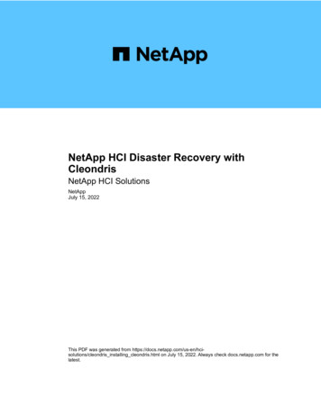
1 IntroductionThis document describes the preferred network architecture for integrating the Mellanox SN2000 family ofEthernet switches into the NetApp HCI system. This information includes network design, cabling, andswitch configuration for small, medium, and large NetApp HCI cluster deployments using the MellanoxSN2010, SN2100, and SN2700 switches. Building high-speed data storage network for various NetAppHCI cluster sizes is the primary focus of this document. As such, we assume that medium size and largerHCI clusters will reside in a datacenter or IT space that has an existing 1/10GbE network for themanagement and out-of-band networks.2 PrerequisitesThis document assumes the following: You are familiar with the content of NetApp HCI Networking Quick Planning Guide. You have completed the NetApp HCI prerequisites checklist. You have not yet deployed the NetApp HCI system software with the NetApp Deployment Engine(NDE). You are ready to rack the Mellanox SN2100 or SN2700 switches, and, given the chosen clusterconfiguration, you have or are ready to purchase the NetApp HCI Mellanox networking kit cables. You are ready to or have already racked all NetApp HCI chassis and installed all NetApp HCI nodes.Additional resources and documentation for NetApp HCI can be found in the NetApp ProductDocumentation center.For detailed information about Mellanox Ethernet switches, see the Mellanox Scale-Out SN2000 EthernetSwitch Series. This webpage includes links to SN2000 series switch family information anddocumentation.3 NetApp HCI Network TopologyNetApp HCI is deployed in clusters that consist of specialized compute and storage resources that areredundantly interconnected to top-of-rack (ToR) network switches. By physically disaggregating thecompute and storage nodes, NetApp HCI can independently scale out to meet the needs of the workload.Figure 1 shows a simplified reference network topology for a single storage node and a single computenode.4NetApp HCI with Mellanox SN2100 and SN2700Network Switch, Best Practice Cabling Guide 2020 NetApp, Inc. All Rights Reserved.
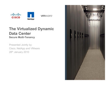
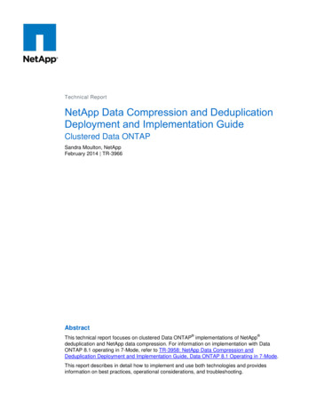
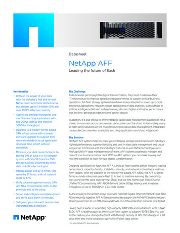
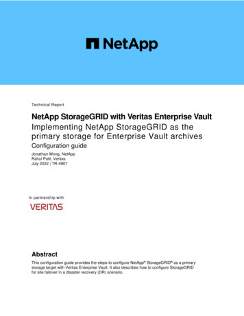
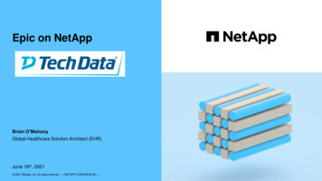
Figure 1) Simplified one compute and one storage node reference network topology for NetApp HCI.Note:The minimum cluster size for NetApp HCI is two storage nodes and two compute nodes, and themaximum cluster size is 40 storage nodes and 64 compute nodes.4 Mellanox Switch OverviewThe Mellanox SN2000 series of Ethernet switches are ideal for ToR leaf and spine use in NetApp HCIsolutions. NetApp HCI requires configuring the switches with the Mellanox Onyx operating system, andairflow is configured in the power cord-to-cable (P2C) direction. The Mellanox Spectrum 1U SwitchSystems Hardware User Manual can be found here.4.1SN2010The Mellanox SN2010 (NetApp PN MSN2010-CB2F-NTAP) is a 1RU-high, half-width switch with 18 portsof 1/10/25GbE and 4 ports of 10/25/40/100GbE. The ideal use case is for small cluster size deploymentsand the inclusion of management network ports (Figure 2).Figure 2) SN2010 faceplate and ports.4.2SN2100The Mellanox SN2100 (NetApp PN MSN2100-CB2F-NTAP) is a 1RU-high, half-width switch with 16 portsof 10/25/40/100GbE in a QSFP transceiver form factor. Its use case is anywhere from small to largecluster sizes. Given that all of the ports are QSFP, 4:1 breakout cables must be used for HCI computeand storage node connections (Figure 3).5NetApp HCI with Mellanox SN2100 and SN2700Network Switch, Best Practice Cabling Guide 2020 NetApp, Inc. All Rights Reserved.
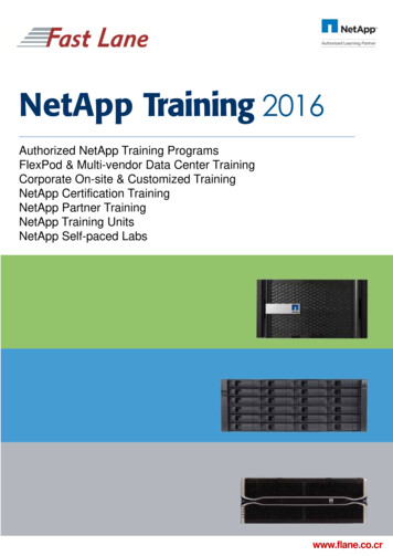
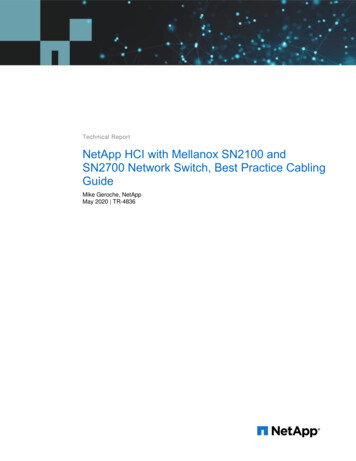
Figure 3) SN2100 faceplate and ports.4.3SN2700The Mellanox SN2700 (NetApp PN MSN2700-CB2F-NTAP) is a 1RU-high, full-width switch with 32 portsof 10/25/40/100GbE in a QSFP transceiver form factor (Figure 4).Figure 4) SN2700 front and back.Note:Note that, while it has 32 ports (double the number of the SN2100), the SN2700 switch can onlysupport 64 connections. When using 4:1 breakout cables for the node connections, half of theQSFP ports are blocked. Therefore, it has the same number of ports for node connections as theSN2100 (Figure 5).Figure 5) QSFP port splitting on the SN2700 with corresponding port deactivation.The SN2700 can be used in place of the SN2100 for spine switching, expansion, and where highserviceability is desired, because the power supplies and fan modules are field-replaceable units. If aPSU or fan module fails, it can be easily be replaced without chassis removal or uncabling while theswitch is operating.6NetApp HCI with Mellanox SN2100 and SN2700Network Switch, Best Practice Cabling Guide 2020 NetApp, Inc. All Rights Reserved.
4.4Breakout Cable UsageThe QSFP ports on SN2100 and SN2700 switches require 4:1 breakout cables to connect to clusternodes. Each QSFP breakout cable connects to four cluster nodes as shown below (Figure 6).Figure 6) QSFP breakout cable for cluster node connections.5 Cluster Network Planning, Connection Diagrams and CablingThe planned number of compute nodes and storage nodes (cluster size) is the primary determining factorin sizing and selecting an appropriate Mellanox Ethernet switch for your HCI deployment. Otherdetermining factors include the management network, out-of-band network, and compute node cabledeployment requirements. The following sections provide various NetApp HCI cluster sizes withrecommended switches and cabling diagrams.5.1Minimum HCI ClusterThe minimum cluster size for NetApp HCI is two storage nodes and two compute nodes. Figure 7 andFigure 8 are network connection diagrams for a minimum-size NetApp HCI system, including all highspeed, management, and out of band networks.7NetApp HCI with Mellanox SN2100 and SN2700Network Switch, Best Practice Cabling Guide 2020 NetApp, Inc. All Rights Reserved.
Figure 7) NetApp HCI minimum size two-storage-node / two-compute-node cluster with high-speed data,management, and OOB networks with 1RU H610S storage with H615C compute nodes.Cabling configuration: High-speed node connections: (8) direct-attach copper Twinax or optical, 10/25GbE Management: (6) Cat 6 RJ-45 for storage management and compute OOB, 1/10GbE Management: (6) 1GbE SFP 1000BASE-T transceiver, adapt SFP to Base-T Storage OOB is assumed to be assigned to the management network. Compute management is onthe high-speed data network (for example, the two-cable option) ISL: (2) QSFP to QSFP copper cable, 100GbE Uplink: (4) optical or Twinax cable, 10/25GbE, or optionally (4) QSFP 100GbEFigure 8) NetApp HCI minimum size two-storage-node / two-compute-node cluster with high-speed data,management and OOB networks with 2RU H410S storage with H410C compute nodes.Cabling configuration: High-speed node connections (12) direct-attach copper Twinax or optical, 10/25GbE Management: (10) Cat 6 RJ-45 for storage management, compute management, and compute OOB,1GbE8NetApp HCI with Mellanox SN2100 and SN2700Network Switch, Best Practice Cabling Guide 2020 NetApp, Inc. All Rights Reserved.
Management; (10) 1GbE SFP 1000BASE-T transceiver, adapt SFP to Base-T ISL: (2) QSFP to QSFP copper cable, 100GbE Uplink: (4) optical or Twinax cable, 10/25GbENetwork notes: In the example above, the SN2010 is connecting the high-speed data network as well as themanagement and out-of-band networks. Compute nodes in Figure 7 use the two-cable option, which combines data and management on asingle interface logically segregated with VLANs. Compute nodes in Figure 8 use the six-cable option, which segregates the data storage, vMotion, andmanagement networks onto separate physical interfaces. The IPMI OOB network is not redundant and is only connected on compute nodes. We assume that storage IPMI OOB network traffic is redirected to the storage management ports,and therefore they are not included in port usage. The network uplinks can be configured on 10/25GbE SFP ports 17 and 18 (as shown), or optionallyconfigured on the 100GbE QSFP ports 19 and 21. A Multi-Chassis Link Aggregation Group (MLAG) must be established between the two ToR switches,and configuring the Link Aggregation Control Protocol (LACP) between the storage nodes andswitches is a best practice. Jumbo frames must be configured on all high-speed interfaces within the HCI cluster network and arerecommended for the network uplinks.5.2Small HCI ClusterSmall cluster sizes range from four storage and four compute nodes up to 12 storage and 12 compute ifthe management and OOB networks are not included on the Mellanox switch (Figure 9).Figure 9) Typical four-storage-node / four-compute-node HCI cluster with data, management, and OOBnetworks.Cabling configuration: High-speed node connections: (12) direct-attach copper Twinax or optical, 10/25GbE Management: (10) Cat 6 RJ-45 for storage management, compute management, and compute OOB,1GbE9NetApp HCI with Mellanox SN2100 and SN2700Network Switch, Best Practice Cabling Guide 2020 NetApp, Inc. All Rights Reserved.
Management: (10) 1GbE SFP 1000BASE-T transceiver, adapt SFP to Base-T ISL: (2) QSFP to QSFP copper cable, 100GbE Uplink: (4) optical or Twinax cable, 10/25GbENetwork notes: This HCI system example is shown using 1RU compute and storage nodes. NetApp HCI systems canalso be configured in 2RU chassis as shown below in Figure 10 with four slots per chassis forcompute or storage resources. The compute IPMI OOB network is not redundant, and connections are split between the A and BToR switches. Optionally, these connections can be connected to a separate, dedicated IPMInetwork.Figure 10) Typical four-storage-node / four-compute-node HCI cluster with data, management, and OOBnetworks, six-cable compute option.Cabling configuration: High-speed node connections: (12) copper Twinax or optical, SFP28 / SFP28, 10/25GbE High-speed node connections: (4) copper Twinax, QSFP / SFP28, 4:1 breakout cables Management: (20) Cat 6 RJ-45 for storage management, compute management, and compute OOB,1GbE Management: (20) 1GbE SFP 1000BASE-T transceiver, adapt SFP to Base-T ISL: (2) QSFP to QSFP copper cable, 100GbE Uplink: (4) optical or Twinax cable, 10/25GbENetwork notes: With 2RU-chassis compute-node models, it is possible to unbundle the management network, thehigh-speed vMotion network, and the high-speed storage network (this option is shown and is calledsix-cable compute). When configuring networks with this cable option, compute nodes use twice thenumber of high-speed data ports (two network switch ports consumed per compute node), and twoadditional Cat 6 ports per node.10NetApp HCI with Mellanox SN2100 and SN2700Network Switch, Best Practice Cabling Guide 2020 NetApp, Inc. All Rights Reserved.
5.3Mid-Size HCI ClustersMedium cluster sizes for NetApp HCI start at 12 storage / 12 compute nodes and range up to 16 storage /32 compute nodes. The SN2100 (or SN2700 if high serviceability is required) is an ideal fit here, becausea single pair of ToR switches can support up to 16 storage and 32 compute node clusters (Figure 11).Figure 11) 16-storage-node / 32-compute-node HCI cluster using one pair of SN2100 ToR switches.Network Notes: Depicted above are the high-speed data network connections. All management and OOB networkports are assumed to be connected to an existing datacenter rack infrastructure. With medium and larger cluster sizes, multiple racks might be required for equipment installdepending on the rack size and datacenter cooling and power concerns. The location of the nodes inthe racks relative to the switches dictate cable length requirements. Other rack node placementconcerns such as protection domains are not within the scope of this document. Each quad breakout cable supports four node connections. These network diagrams show each ofthese breakouts connected to either storage or compute nodes (not intermixed). This configuration isused for ease of switch programmability but is not a requirement. Uplinks to the data center network can be 10GbE or 25GbE if interfaces are split, or 100GbE nativelyusing QSFP. It is a best practice is to use multiple uplinks configured with link aggregation.5.4Large HCI ClustersCluster sizes beyond 16 storage and 32 compute nodes require multiple pairs of ToR switches,configured in a full mesh spine-and-leaf, scale-out arrangement. Configured as such, two pairs of ToRswitches can support a maximum of 64 compute and 32 storage nodes (Figure 12 and Figure 13).11NetApp HCI with Mellanox SN2100 and SN2700Network Switch, Best Practice Cabling Guide 2020 NetApp, Inc. All Rights Reserved.
Figure 12) Large-size HCI cluster with maximum number of compute nodes (64).Figure 13) Large-size HCI cluster with maximum number of storage nodes (40).Network Notes: As with leaf ToR pairs, spine switch pairs are required to be interconnected with MLAG. Multiple network uplinks are shown at 100GbE connectivity. Configured this way, the SN2700 spinedoes not block the corresponding port beneath. See Section 4.3, Figure 5 for the blocking diagram. If your data center cannot connect to 100GbE QSFP uplink ports, you can split the uplink ports andconnect at 10GbE or 25GbE. In this case, the ports beneath are blocked as shown in Section 4.3,Figure 5.5.5Maximum Size HCI ClusterA maximum cluster size of 64 compute and 40 storage nodes requires three pairs of ToR leaf switchesconnected to a spine switch layer (Figure 14).12NetApp HCI with Mellanox SN2100 and SN2700Network Switch, Best Practice Cabling Guide 2020 NetApp, Inc. All Rights Reserved.
Figure 14) NetApp HCI maximum cluster size, 64 compute and 40 storage nodes.Network Notes: Additional leaf pairs require a set of connections to each spine switch. Therefore, with a single pair ofspine switches, you can support multiple clusters.5.6NetApp Orderable Cabling for Mellanox SwitchesTable 1) Network cables for node-to-switch and switch-to-switch connections.Marketing Part No.Item DescriptionUse CaseX6584-R61Gb cables, 1mCat 6 RJ-45 Ethernet cableX6585-R61Gb cables, 3mCat 6 RJ-45 Ethernet cableMCP2M00A001E30NCable, 25Gb, copper, SFP28-SFP28, 1mNode to SN2010 SFP28 switch portMCP2M00A003E30LCable, 25Gb, copper, SFP28-SFP28, 3mNode to SN2010 SFP28 switch portMCP1600C00AE30NCable, 100Gb, copper, QSFP-QSFP,0.5mSwitch-to-switch ISL QSFP portsMCP1600C001E30NCable, 100Gb, copper, QSFP-QSFP, 1mSwitch-to-switch ISL QSFP portsMCP1600-C003E30L Cable, 100Gb, copper, QSFP-QSFP, 3mSwitch-to-switch ISL QSFP portsMCP7F00A01AR30NCable, 4x25Gb, copper, QSFP-SFP28,1.5m4:1 breakout, switch QSFP port to nodeMCP7F00A003R30LCable, 4x25Gb, copper, QSFP-SFP28,3m4:1 breakout, switch QSFP port to nodeMC3208411-TSFP optical, 1GbE Base-T, RJ45SN2010 1GbE management connectionsMFM1T02A-SRSFP optical, LC, 10GbE, 300m, SR10GbE short-reach optical transceiverMFM1T02A-LRSFP optical, LC, 10GbE, 10km, LR10GbE long-reach optical transceiver13NetApp HCI with Mellanox SN2100 and SN2700Network Switch, Best Practice Cabling Guide 2020 NetApp, Inc. All Rights Reserved.
Marketing Part No.Item DescriptionUse CaseMMA2P00-AS-SPSFP28 optical, LC, 25GbE, 100m, SR25GbE short-reach optical transceiverMMA2L20-ARSFP28 optical, LC, 25GbE, 10km, LR25GbE long-reach optical transceiverMMA1B00-C100DQSFP28 optical, MPO, 100GbE, 100m,SR4Optical transceiver for switch-to-switchISL QSFP portsMMA1L10-CRQSFP28 optical, LC, 100GbE, 10km, LR4 Optical transceiver for long-range ISLQSFP ports6 General Switch Configuration, Small Cluster Network Example6.1General Protocol RequirementsAdherence to the cabling diagrams above is essential to availability, performance, and extensibility ofNetApp HCI. A fully redundant and fault-tolerant network is required for proper operation. Switchprotocols such as LACP and MLAG are required to make sure that redundant links are readily availableand performance is optimized.Note:The following Mellanox switch CLI code examples are not necessarily tied to any specific networkconfiguration or drawing above. Use these as examples on how to program the switch for yourspecific network connection diagram. Consult NetApp Professional Services for additionalspecifics.#Example for Mellanox SN2000 Series Switches Protocol Services#Configuration steps are in order they should be entered#Enable Servicesprotocol mlaglacplldpip routing vrf defaultdcb priority-flow-control enable forcewhat-just-happened all enable#Allow these commands to fully complete before continuingNote:6.2These commands must be executed in order first and allowed to complete before continuing.VLAN RequirementsNetApp HCI requires logically separate networks (VLANs) for leaf MLAG domains, spine MLAG domains,management, iSCSI storage, virtual machine (VM) migration (vMotion), and VM data.#Configure VLANsvlan 4000 name “Leaf 1 IPL VLAN”exitvlan 100 name “HCI Management”exitvlan 101 name "HCI iSCSI Storage"exitvlan 102 name "HCI vMotion"exitvlan 103 name “HCI Guest VM1 Network”exit14NetApp HCI with Mellanox SN2100 and SN2700Network Switch, Best Practice Cabling Guide 2020 NetApp, Inc. All Rights Reserved.
6.3Configure Switch -to-Switch Inter-Peer Link and Multi-Chassis LinkAggregationMLAG configuration is required between pairs of ToR leaf or spine switches. IP addresses for Inter-PeerLinks (IPLs) are private between the MLAG pair and can be the same as other switch pairs.#Configure IPLinterface port-channel 100description IPLexitinterface ethernet 1/20 channel-group 100 mode activeinterface ethernet 1/20 description ISL to partner ToR Switchinterface ethernet 1/22 channel-group 100 mode activeinterface ethernet 1/22 description ISL to partner ToR Switchinterface port-channel 100 ipl 1interface port-channel 100 dcb priority-flow-control mode on forceinterface vlan 4000exit#IPL Ip should *not* be in the management networkinterface vlan 4000 ip address 10.255.255.1 255.255.255.252interface vlan 4000 ip1 1 peer-address 10.255.255.2#Configure MLAG VIP#Both MLAG name and ip must be unique#MLAG IP *should* be in the management networkmlag-vip MLAG-VIP-DOM ip 10.xxx.xxx.174 /24 force#mlag system mac can be any unicast MACmlag system-mac 00:00:5E:00:AA:01no mlag shutdownNote:6.4The previous example assumes the IPLs between the two ToR switches are on ports 20 and 22.Also note that the corresponding partner ToR switch interchanges the IP addresses in the peeraddress command (highlighted).Configure UplinkThe network uplinks should be configured to match the speed of the corresponding network data centerport capability. The following example assumes a 10GbE connection speed, and network uplinks on ports17 and 18. It is also preferred (but not required) to configure jumbo frames on the uplinks.#Configure Uplinkinterface mlag-port-channel 101description Uplink to Datacenterexitinterface ethernet 1/17 description Network Uplink Ainterface ethernet 1/17 speed 10000 forceinterface ethernet 1/18 description Network Uplink Binterface ethernet 1/18 speed 10000 forceinterface mlag-port-channel 101 mtu 9216 forceinterface ethernet 1/17 mlag-channel-group 101 mode activeinterface ethernet 1/18 mlag-channel-group 101 mode activeinterface mlag-port-channel 101 switchport mode trunkinterface mlag-port-channel 101 switchport trunk allowed-vlan allinterface mlag-port-channel 101 no shutdown6.5Configure Management PortsThis section is included for smaller installations that include management ports in the switch setup. Allnode ports should have a spanning tree configured to enter a forwarding state immediately (RapidSpanning Tree Protocol). These commands can be used as an example on how to configure themanagement network on an existing datacenter 1GbE rack infrastructure.#Configure Management Ports (Storage Node Management)interface ethernet 1/1-1/4 spanning-tree bpdufilter enableinterface ethernet 1/1-1/4 spanning-tree port type edge15NetApp HCI with Mellanox SN2100 and SN2700Network Switch, Best Practice Cabling Guide 2020 NetApp, Inc. All Rights Reserved.
interface ethernet 1/1-1/4 spanning-tree bpduguard enableinterface ethernet 1/1-1/4 speed 1000 forceinterface ethernet 1/1-1/4 switchport mode accessinterface ethernet 1/1 description HCI-Storage Node 1 Management Portinterface ethernet 1/2 description HCI-Storage Node 2 Management Portinterface ethernet 1/3 description HCI-Storage Node 3 Management Portinterface ethernet 1/4 description HCI-Storage Node 4 Management Portinterface ethernet 1/1 switchport access vlan 100interface ethernet 1/2 switchport access vlan 100interface ethernet 1/3 switchport access vlan 100interface ethernet 1/4 switchport access vlan 100#Configure Out-of-Band Ports (Storage Node OOB for ToR “A” switch, Computeinterface ethernet 1/13-1/16 spanning-tree bpdufilter enableinterface ethernet 1/13-1/16 spanning-tree port type edgeinterface ethernet 1/13-1/16 spanning-tree bpduguard enableinterface ethernet 1/13-1/16 speed 1000 forceinterface ethernet 1/13-1/16 switchport mode accessinterface ethernet 1/13 description HCI-Storage/Compute Node 1 IPMI OOBinterface ethernet 1/14 description HCI-Storage/Compute Node 2 IPMI OOBinterface ethernet 1/15 description HCI-Storage/Compute Node 3 IPMI OOBinterface ethernet 1/16 description HCI-Storage/Compute Node 4 IPMI OOBinterface ethernet 1/13 switchport access vlan 100interface ethernet 1/14 switchport access vlan 100interface ethernet 1/15 switchport access vlan 100interface ethernet 1/16 switchport access vlan 100Note:6.6Node OOB for rtPortPortPortWhen using the compute node two-cable option, the management network for compute nodes iscombined with vMotion and guest VM data traffic on the high-speed data network and logicallyseparated with VLANs. Also, you can optionally assign OOB network access to the managementnetwork on the storage nodes, which does not require separate connections.Configure Storage Ports, iSCSI Network#Configure iSCSI Ports (storage nodes)interface ethernet 1/5-1/8 spanning-tree port type edgeinterface ethernet 1/5-1/8 spanning-tree bpduguard enableinterface ethernet 1/5-1/8 lacp port-priority 10interface ethernet 1/5-1/8 lacp rate fastinterface ethernet 1/5 description STORAGE Node 1interface ethernet 1/6 description STORAGE Node 2interface ethernet 1/7 description STORAGE Node 3interface ethernet 1/8 description STORAGE Node 4interface mlag-port-channel 201-204exitinterface ethernet 1/5 mlag-channel-group 201 mode activeinterface ethernet 1/6 mlag-channel-group 202 mode activeinterface ethernet 1/7 mlag-channel-group 203 mode activeinterface ethernet 1/8 mlag-channel-group 204 mode activeinterface mlag-port-channel 201-204 mtu 9216 forceinterface mlag-port-channel 201-204 lacp-individual enable forceinterface mlag-port-channel 201-204 no shutdowninterface mlag-port-channel 201-204 switchport mode hybridinterface mlag-port-channel 201 switchport hybrid allowed-vlan allinterface mlag-port-channel 202 switchport hyb
The Mellanox SN2010 (NetApp PN MSN2010-CB2F-NTAP) is a 1RU-high, half-width switch with 18 ports of 1/10/25GbE and 4 ports of 10/25/40/100GbE. The ideal use case is for small cluster size deployments and the inclusion of management network ports (Figure 2). Figure 2) SN2010 faceplate and ports. 4.2 SN2100