Transcription
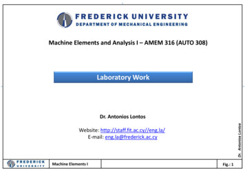
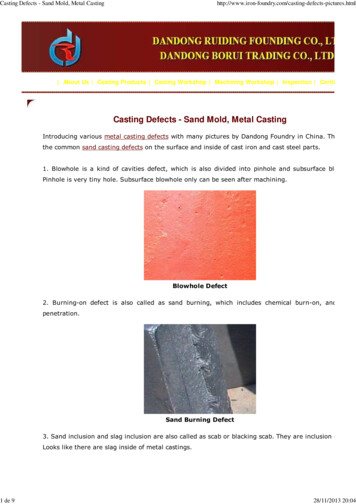
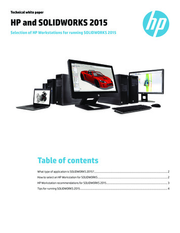
CAE DS – Casting Design Exercises ‐ SolidWorksCasting Design Exercises– Basic Skills 1: Extruding andsketchingTuula Höök, Tampere University of TechnologyWhat is new in this exercise?‐ Sketch tool‐ Extruded Boss/Base tool‐ Extruded Cut tool‐ Swept Boss/Base tool‐ Chamfer tool‐ Fillet tool‐ Shell toolExercise 1.1To do:The model is a flat, symmetric part with a chamfered hole in each corner.Produce the model by using Extruded Boss/Base tool, Extruded Cut tooland Chamfer tool. As an option make all edges round with 1 mm radius fillet. See thefinished example model. Some of the edges are not filleted. Why?1
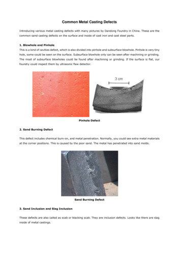
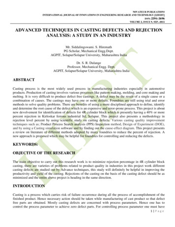
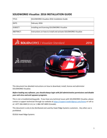
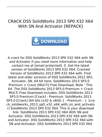
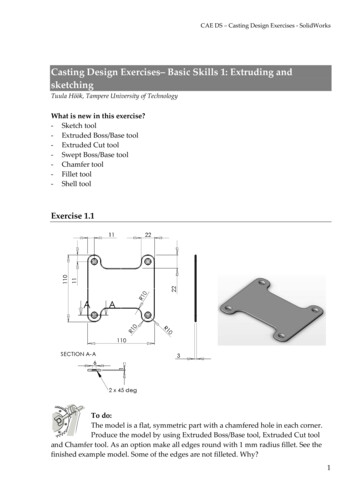
CAE DS – Casting Design Exercises ‐ SolidWorksExercise 1.2To do:The model is a symmetric, cup‐shaped part with rounded (filleted) cornersin sides and in the bottom. There are different ways to prepare this part.Take these steps: Sketch the shape shown in the figure above, extrude it,fillet vertical edges and bottom edges and finally make a 1,5 mm thick shell from theextruded and rounded solid. You can also produce the part by sketching the shape withalready rounded corners, extruding, rounding the bottom and finally producing theshell.Exercise 1.3Trajectory (path of the sweep.Profile for the cup wall, or profile to sweep along thetrajectory. Sketch the profile so that it is coincidentwith the trajectory.To do:The model is a symmetric cup‐shaped part with a collar around. Producethe model by using Swept Boss/Base and Extruded Boss/Base tools.2
CAE DS – Casting Design Exercises ‐ SolidWorksInstructionsSketching1. Start the Sketch tool by selecting the Sketchcommands from the upper left corner of theSolidWorks window. A Sketch paletteopens to the upper right corner of thewindow.Select the Sketchplane2. Select a plane for sketching. The plane canbe one of the model faces, a reference planeor one of the basic planes: Front, Top orRight plane. Select the plane from thefeature tree on the left side of the screen.3. Sketch something, which looks like thedesired shape. See figure on the left.4. Notice the hole in the upper left side of thesketch. Do not put an extra line there. Useone of the sketch entity relations (Merge) toclose the sketch.5. Select the endpoints from both of the linesyou wish to close. Use Control (Ctrl) key toselect more than one entity. If you selectone or more sketch entities a Propertieswindow appear to the left side of theSolidWorks window into the place of thefeature tree. In the Properties window youcan see the relations and other properties,which are possible to change in the selectedsketch entity. In this case select Merge andthe two endpoints come together and closethe sketch.6. Use other sketch entity relations to makeyour sketch look more like the final shape.Typical sketch entity relations are:Horizontal, Vertical, Colinear,Perpendicular, Parallel, Equal, Midpointand Coincident. Try these.3
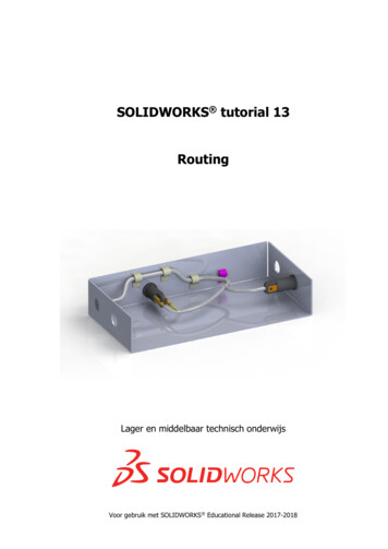
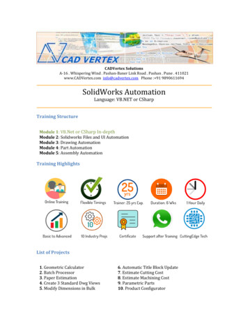
CAE DS – Casting Design Exercises ‐ SolidWorks7. Finally add dimensions to the sketch. SelectSmart Dimension from the Sketch palette. Selectthe sketch entity or the sketch entities you wishto add dimension. Once you release the mousebutton a Modify window appears and you canwrite the dimension you wish.Producing symmetry to a sketch with centerlines1. SolidWorks has a very handy symmetrytool in the sketch entities: the Centerline.In the exercise 1.1 you need to produce asymmetric, extruded part. Use theCenterline entity.2. Draw centerlines like in the figure on theleft. The horizontal and verticalcenterlines are drawn by using the linemiddlepoints. If you move the mousecursor near the line middlepoint,SolidWorks shows you this entity andyou can select it.3. Use midpoint relation with the sketchorigin with all centerlines. The sketchbecomes symmetrical and there is less todimension. Try this by changingdimensions.4
CAE DS – Casting Design Exercises ‐ SolidWorksProducing symmetry to a sketch by mirroringStarting phaseFinished1. Sketch the entities you wish to mirror. In this example the finished part issymmetrical in two directions. There is a need to produce only a quarter of thefinal product.2. Open the Mirror tool. You can find in under theTools menu. Tools‐ Sketch Tools‐ Mirror. Orfrom the Sketch palette. SolidWorks hides thetools that do not fit into the window. You canfind the hidden tools from the place shown in ttefigure on the left.3. With the mirror tool active, select the entitiesyou wish to mirror and the axis to mirror about.You can mirror only to a one direction at a time.5
CAE DS – Casting Design Exercises ‐ SolidWorksExtruding a solidStarting phaseFinishedView of the tool window1. Select Features from the upper left corner of the SolidWorks window. A Featurespalette appears to the upper right part of the window. Select Extruded Boss/Basefrom the palette.2. This tool needs you to prepare a sketch, which is then extruded. SolidWorksgives you two options: To select an existing sketch or to select a plane to startsketching. If you already have a sketch, select it and you will enter the stateshown in the figure on the left. If not, start sketching. When you have finishedthe sketch, exit the sketching state and you will be able to start giving theextruded boss properties as when started with the already existing sketch.3. Give a dimension to the extrude. There are different options to constraining anddimensioning the extrude. See SolidWorks help file to see the options and trythem. When there is only one feature and one sketch, the number of possibleoptions is limited.6
CAE DS – Casting Design Exercises ‐ SolidWorksExtruding a cutStarting phaseFinishedView of the tool window1. Select Features from the upper left corner of the SolidWorks window. A Featurespalette appears to the upper right part of the window. Select Extruded Cut fromthe palette.2. It is obvious that you need somethingto cut before you can add a ExtrudedCut feature. This tool needs you toprepare a sketch to give dimensionsto an extruded cut. You can use oneSelect planes hereof the solid model faces as a sketchplane or use one of the model basicplanes: Front, Top or Right plane.Solid Works asks you to select anOr sketch here on theexisting sketch or to sketch one. Youmodel facecan select basic planes from thefeature tree that has appeared to theSolidWorks model window.3. After you have selected the sketch or prepared the sketch and exit the sketchingstate you will enter the Extruded Cut feature state. Enter the dimensions andother properties. You will see the result in the model window. Notice that youcan change the extruded cut direction. The direction shown in the figure iswrong and will cause an error.4. If you are preparing a hole that should extend trough a feature, use some otherthan Blind direction. For example use the ‘Up to surface’ option. Try this.7
CAE DS – Casting Design Exercises ‐ SolidWorksChamfering featuresStarting phaseFinishedView of the tool window1. Select Features from the upper left corner of the SolidWorks window. A Featurespalette appears to the upper right part of the window. Select Chamfer from thepalette. You can select Chamfer also from the Insert menu. Insert‐ Features‐ Chamfer.2. Give the dimensions and other options as you wish. One by one select theentities you want to chamfer and press OK. Try different options. If youmistakenly select a wrong entity, selecting it one more clears the selection. Youcan also delete entities from the Chamfer parameters window.Filleting featuresStarting phaseFinishedView of the tool window8
CAE DS – Casting Design Exercises ‐ SolidWorks1. Select Features from the upper left corner of the SolidWorks window. A Featurespalette appears to the upper right part of the window. Select Fillet from thepalette. You can select Fillet also from the Insert menu. Insert‐ Features‐ Fillet/Round.2. Give a radius for the fillet. Select all the edges you wish to fillet. Be careful not toselect edges that cross each other. Try to fillet edges in a different order and seewhat happens. In the example in the figure ‘View of the tool window’ it is betterto choose the vertical lines first and after that fillet the vertical edges.Making a shell from a solidStarting phaseFinishedView of the tool window1. Select Features from the upper left corner of the SolidWorks window. A Featurespalette appears to the upper right part of the window. Select Shell from thepalette. You can select Shell also from the Insert menu. Insert‐ Features‐ Shell.2. Insert the wall thickness to the shell.3. If you wish to remove one or more faces, select them. If you do not select anyfaces the solid will be hollow having the wall thickness you already have chosen.9
CAE DS – Casting Design Exercises ‐ SolidWorksSweeping a solidStarting phaseFinishedView of the tool window1. Select Features from the upper left corner of the SolidWorks window. A Featurespalette appears to the upper right part of the window. Select Shell from thepalette. You can select Shell also from the Insert menu. Insert‐ Features‐ Shell.2. The tool needs you to prepare two sketches: One for path and one for profile. Theprofile should lie on the path. The profile and path are perpendicular to eachother.3. You can set different options for this tool. See SolidWorks help for moreinstructions. For example it is possible to use guide curves and set the end andstart tangency for open profiles.10
1. SolidWorks has a very handy symmetry tool in the sketch entities: the Centerline. In the exercise 1.1 you need to produce a symmetric, extruded part. Use the Centerline entity. 2. Draw centerlines like in the figure on the left. The horizontal and vertical centerlines are drawn by using the line