Transcription
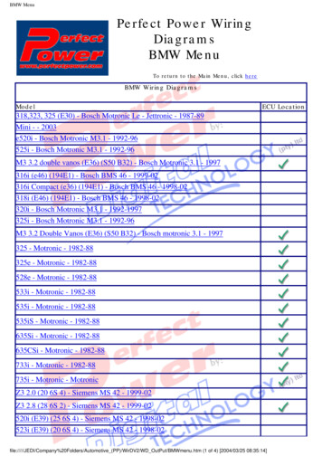
Digital axis controlRE 30239Edition: 2015-02Replaces: 2014-09Type VT-HMC Component series 1XHMC 25093 dFeaturesContents FeaturesOrdering codeFunctionOverview of the controller functionsSystem overview (example)Technical dataPin assignment VT-HMC-1-1XDimensionsProject planning/maintenance instructions/additional informationPLC functionality to IEC 61131-3Digital axis controller for an electro-hydraulic axisBEST IN CLASS hydraulic controllerBus connection (slave)/service interface (TCP/IP)selectable by parameter (Sercos, EtherNET IP, PROFINET RT, EtherCAT, PROFIBUS) Hydraulic axes measuring system:–– incremental or absolute (SSI, Endat2.2)–– analog 10 V and 4 to 20 mA (in preparation) CE mark according to EMC Directive 2004/108/EC123456 891011RE 30239, edition: 2015-02, Bosch Rexroth AG
VT-HMC Digital Axis Control2/12Ordering C01Motion for hydraulic drives021 axis03Component series 10 to 19 (10 to 19: unchanged technical data and pin assignment)1X04Multi EthernetM05With ProfibusPWithout Profibus0106Software option: Standard0007Hardware option: Standard00Available variantsTypeMaterial 00/00R901361305Included within the scope of delivery:Mating connector for XD1 (Weidmüller BLZF 3.50/03/180F SN BK BX) XG20 (Weidmüller B2CF 3.50/30/180LH SN BK BX)Recommended accessories (can be ordered separately)DesignationMaterial no.CONNECTOR 6ES7972-0BA42-0XA0 for connection XF30 (Profibus)R901312863Connection cable PC VT-HMC (RJ45, XF20 or XF21) RKB0011/005.0 length: 5 mR911321548Commissioning software IndraWorks DS from version 13V14 (without PLC functionality)‒Commissioning software IndraWorks MLD from version 13V14‒Commissioning software IndraWorks Suite from 13V14‒Bosch Rexroth AG, RE 30239, edition: 2015-02
Digital axis control VT-HMC 3/12FunctionDescriptionThe VT-HMC (Hydraulic Motion Controller) is a digitalcontroller with integrated axis controller, which can beprogrammed according to IEC 61131.The following controller functions are available: Position controlForce controlPressure controlAlternating control (position/pressure and force)Velocity controlThis enables, amongst others, the following operatingmodes: Valve direct control Drive-controlled position control Drive-controlled positioning Positioning block operationThe command values are specified via the Bus interface(XF20/XF21 or XF30), via the analog interface (XG20) oralternatively via an internal PLC program.PC program IndraWorks MLD or DSTo implement the project planning task and toparameterize the VT-HMC valves, the user may use theIndraWorks engineering tool (see accessories): Project planning Parameterization Creating the PLC program (prerequisite IndraWorks MLD) Commissioning Diagnosis Comfortable management of all data on a PC Prerequisite: PC operating system Windows 7Slot for an SD memory cardThe following data can be stored: PLC program Any other dataOnly SD memory cards with SPI bus connection aresupported (no SDHC memory cards).The card must be inserted when switching on otherwise itwill not be recognized. An automatic formatting (FAT 32) iscarried out non-FAT-formatted cards.The feedback information of the actual value signals to thesuperior control system is provided optionally either viathe Bus interface (XF20/XF21 or XF30) or the analog/digital interface (XG20).The control parameters are set via one of the two Ethernetinterfaces (XF20/XF21) (switch functionality integrated)MonitoringThe digital control electronics enables comprehensivemonitoring functions/fault detection including: Undervoltage Communication error Cable break for analog sensor inputs (4 . 20 mA) anddigital position measurement system Short-circuit monitoring for analog/digital outputs Monitoring of the microcontroller (watchdog) Temperature of the integrated electronics Over-current of 24 V sensor voltages and thedigital outputsRE 30239, edition: 2015-02, Bosch Rexroth AG
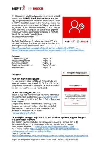
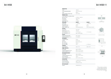
4/12VT-HMC Digital Axis ControlOverview of the controller functionsBus:Sercos III,PROFINET RT,EtherNet/IP,EtherCAT, TCP/IP internal PLCPROFIBUS DP(only for -P- variants) Analog signalAnalog signalAnalog outputCommandvaluegeneratorActual valuetreatment Force controllerPositioncontroller Substitutional control Actuating variable adaptationAnalog output forvalve withintegratedelectronicsPressuretransducer 1Pressuretransducer 2Digital positiontransducersBosch Rexroth AG, RE 30239, edition: 2015-02
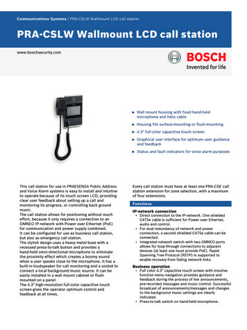
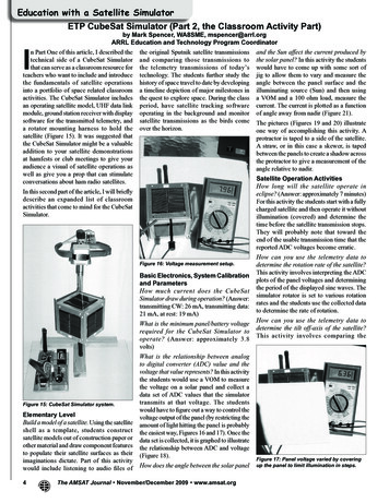
Digital axis control VT-HMC 5/12System overview (example)Control (PLC)Visualization (HMI)Sercos III,PROFINET RT,EtherNet/IP, EtherCAT,PROFIBUS DPDigital axis controlVT-HMCDigital inputs/outputs,analog inputs/outputsDigital inputs/outputs,analog inputs/outputsPosition:SSI/EnDat 2.2or incremental oranalog(in preparation)Voltage supply24 V DCPressuretransducerHM20-2XPressure rod side4 . 20 mA/0.1 . 10 VPressure, piston side 4 . 20 mA/0.1 . 10 VRE 30239, edition: 2015-02, Bosch Rexroth AG
VT-HMC Digital Axis Control6/12Technical data(For applications outside these parameters, please consult us!)Operating voltage‒ Nominal voltageUB 24 V DC– Lower limitUBmin. 17.5 V DC‒ Upper limitUBmax. 30 V DC‒ Maximum admissible residual ripple (40 . 400Hz)Current consumption, totalu 5 Vpp (observe admissible limits)I One axis:‒ Idle state: 0.2 0.3 A‒ max. admissible load: 0.9 1.1 A(external fuse protection required)Power dissipation (at 24 V) 8WExternal fuse3.15 A slow-blowBus systemsPROFIBUS DP (max. 12 MBaud according to IEC 61158),Sercos III, PROFINET RT, EtherNet/IP, EtherCATParameterization interfaceEthernetScan time position controller (minimum)0.5 msecBoot time 15 sec (from switching on until the position control is active)Digital inputs Di‒ Quantity4‒ Low - levelU -3 V 5 V‒ High - levelU 11 V UB‒ Current consumption at high - level‒ Reference potentialI 2 mA 15 mAGNDDigital outputs Do‒ Quantity‒ Low - level‒ High - level‒ Current carrying capacity‒ Signal delay time‒ Reference potential2U 0 3VU 14.5 V UBImax. 50 mA (short-circuit-proof)t 0.5 ms 1.2 ms (depending on selected performance)GNDAnalog inputs Ai‒ Number (current or voltage input configurable)4‒ Resolution14 Bit1)– Voltage inputs (differential inputs) Measurement rangeUE -10 V 10 V Input resistanceRE 200 kΩ 10 % Linearity at 20 CU 20 mV NoiseU 15 mV Temperature drift 12 mV/10 K– Current inputs (based on AGND) Input current Input resistance Linearity at 20 C Temperature drift1)based on 12 V (1.465 mV/Bit) and 20.7 mA (1.27 µA/Bit)2)0.334 mV/BitBosch Rexroth AG, RE 30239, edition: 2015-02IE 4 mA 20 mA (0 20 mA physically)RE 100 Ω measuring resistance plus FET plus diodeI 20 μA 12 μA/10 K
Digital axis control VT-HMC 7/12Technical data(For applications outside these parameters, please consult us!)Supply for sensors Vgeber ANA‒ Supply voltageU UB ‒ 4 V (max. load) . UB ‒ 2.5 V (idle state)– Maximum supply currentI 100 mAAnalog outputs Ao‒ Number (current or voltage input individually configurable)2‒ Resolution16 Bit2)– Voltage outputs Output rangeU –10 V 10 V (0 10 V via software) Minimum load impedanceZ 1000 Ω Linearity and noise at 20 CU 25 mV Temperature drift 12 mV/10 K‒ Current outputs Output range Maximum loadI 0 20 mA (4 mA 20 mA via software)R 500 Ω Linearity and noise at 20 CI 35 μA Temperature drift 12 μA/10 KDigital position transducers (encoders)‒ Voltage supply for encoder (optional) 5 VencU 5 VDC 5 % Vgeber SSIU UB ‒ 3 V (max. load) . UB (idle state)‒ Maximum supply currentI 300 mA‒ Incremental transducer (transducer with TTL output) Encoder signalsTwo pulse series (A and B, 90 moved electrically) and a referencesignal (Z) or single-ended Signal formRS485 Maximum input frequency250 kHz‒ SSI transducer (due to better control quality a transducerwith clock synchronization should be used) CodingGray Data width18 28 Bit Transfer frequency80 500 kBit/s Line receiver / line driverRS 485‒ EnDat encoder2.2RE 30239, edition: 2015-02, Bosch Rexroth AG
8/12VT-HMC Digital Axis ControlTechnical data(For applications outside these parameters, please consult us!)Environmental conditions, other information‒ Protection class according to EN 60529IP20‒ Ambient temperature range–20 C 60 C‒ Maximum permissible temperature change5 C/min‒ Transport temperature range–40 C 70 C‒ Recommended storage temperature range with UVprotection 5 C 40 C‒ Relative air humidity10 95 % (without condensation)‒ Max. altitude2000 m‒ UV resistanceHousing is only partially UV-resistant. There may be color changes.when subject to longer periods of radiation.‒ Transport shock according to DIN EN 60068-2-2715 g / 11 ms / 3 axes‒ Sine test according to DIN EN 60068-2-610 500 Hz / maximal 2 g / 10 cycles / 3 axes‒ Noise test according to DIN EN 60068-2-6420 500 Hz / 2.2 g RMS / 6.6 g peak / 30 min. / 3 axes‒ Free fall (in original packaging)1 m (see 61131-2)‒ Electro-magnetic compatibility (EMC) EN 61000-6-2 / EN 61131-2 EN 61000-4-2 ESD4 kV CD / 8 kV AD with BWK B EN 61000-4-3 HF radiated10 V/m (80 2700 MHz) with BWK A EN 61000-4-4 burst2 kV with BWK B EN 61000-4-5 surge0.5 kV / (sym. / unsym.) with BWK B EN 61000-4-6 HF cable-propagated0 Veff (150 kHz 80 MHz) with BWK A EN 61000-4-8 magnetic field 50/60 Hz100 A/m with BWK A EN 61000-6-3 / EN 61000-6-4 / EN 61131-2 EN 55016-2-1 radio interference voltage0.15 30 MHz, class A, EN 55022 EN 55016-2-3 Radio interference field strength30 1000 MHz, class A, EN 55022‒ Installation positionVertical. For ventilation of the assembly the vents on the top andbottom must be kept at least 2 cm away from covers, walls etc.‒ AssemblyTop hat rail TH35-7.5 or TH35-15 according to EN 60715‒ Housing materialGlass fiber reinforced polyamide plastic‒ Resistance to aggressive mediaContact with conductive dust is not permissible. Avoid contact withhydraulic fluids.‒ Weightm 0.6 kg‒ Dimensionssee page 10‒ ConformityCE according to EMC DirectiveCE according to EMC DirectiveBosch Rexroth AG, RE 30239, edition: 2015-02
Digital axis control VT-HMC 9/12Pin assignment VT-HMC-1-1X (1-axis version)XG20, Encoder/DIO/AIOSignalPinPinSignalVencoder ANA (UB 2))a1b1AGNDAi1 a2b2Ai1‒/Cin11)Ai2 a3b3Ai2‒/Cin21)Ai3 a4b4Ai3‒/Cin31)Ai4 a5b5Ai4‒/Cin41)Ao1a6b6AGNDAo2a7b7AGNDDi1a8b8Di2 Di3a9b9Di4 a10b10Do2 R‒a11b11R CLK‒/A‒a12b12CLK /A Data‒/B‒a13b13Data /B 5Venca14b14GNDVencoder SSI (UB 2))a15b15GND Do1 2)Only wire current inputs (Cin) to pin b2 b5, leave pin a2 a5open. Reference potential: AGND (also see notes in the operatinginstructions 30239-B) See technical data for voltage range 1) XF20, XF21Ethernet connectionsSignalPinTD 1TD‒2RD 3‒4‒5RD‒7‒8XD1, Power 6‒XF30, PROFIBUS DP (only for erved3 Ub(17.5 V 30 V)3RxD/TxD-P4CNTR -P5DGND6VP7reserved8RxD/TxD -N9reservedRE 30239, edition: 2015-02, Bosch Rexroth AG
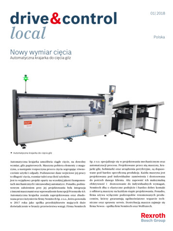
10/12VT-HMC Digital Axis ControlDimensions(dimensions in mm) 1)Plus 15 mm for connecting/disconnecting the plug-in connectorBosch Rexroth AG, RE 30239, edition: 2015-02
Digital axis control VT-HMC 11/12Project planning/maintenance instructions/additional informationProduct documentation for VT-HMC: Data sheet 30239 (this data sheet) Operating instructions 30239-B CE declaration of conformity(available from Bosch Rexroth upon request) Operation VT-HMC (from 18V12 software version):–– Functional description Rexroth HydraulicDrivefrom HDx-18–– Parameter description Rexroth HydraulicDrivefrom HDx18 RD30330-PA–– Diagnosis description Rexroth HydraulicDrivefrom HDx18 RD3030-WA–– Library description Rexroth HydraulicDrive, RexrothIndraMotion MLD (2G), libraries from HDx-18–– MLD application description General information on the maintenance andcommissioning of hydraulic components data sheet07800/07900Commissioning software and documentation on theInternet: www.boschrexroth.com/HMCMaintenance instructions: The devices have been tested in the plant and aresupplied with default settings. Only complete units can be repaired. Repaired devicesare returned with default settings. User-specific settingsare not maintained. The machine end-user will have toretransfer the corresponding user parameters.1)Notices: The supply voltage must be permanently connected,as otherwise bus communication is not possible. In particular EMC-sensitive environments, additionalmeasures must be taken (depending on the application, e.g. shielding, filtering) 1) Wiring instructions–– Maximum spatial separation of signal and loadlines.–– Do not lead signal lines through magnetic fields.–– Install signal lines as far as possible withoutintermediate terminals.–– Do not install signal lines parallel to the load lines.–– Install cable shields (see operating instructions).–– The max. cable length of 30 m is recommendedfor digital inputs and outputs.–– Sensors (incremental, absolute or analog) mayonly be used with shielded cables. Max. recommended cable length: 50 m, in addition thesensor manufacturer's instructions are to beobserved.–– The signals of the connector XG20 are not galvanically separated. A potential reference is always tobe produced when connecting external devices. For more information see Indraworks online helpand operating manual 30239-B. The upper and lower ventilation slots must not beconcealed by adjacent units in order to provide forsufficient cooling. Observe the installation information in operatinginstructions 30239-B.In accordance with the emissions requirements according toEN61000-6-3 special precautions must be taken when usingthe HMC in the household/small commercial areas, such asinstallation in a shielded enclosure and the use of appropriatelyapproved filter devices.RE 30239, edition: 2015-02, Bosch Rexroth AG
12/12VT-HMC Digital Axis ControlNotesBosch Rexroth AGHydraulicsZum Eisengießer 197816 Lohr am Main, GermanyTelefon 49 (0) 93 52 / deBosch Rexroth AG, RE 30239, edition: 2015-02 This document, as well as the data, specifications and other information setforth in it, are the exclusive property of Bosch Rexroth AG. It may not bereproduced or given to third parties without the consent of Bosch Rexroth AG.The data specified above only serve to describe the product. No statementsconcerning a certain condition or suitability for a certain application can bederived from our information. The information given does not release the userfrom the obligation of own judgment and verification.It must be remembered that our products are subject to a natural process ofwear and aging.
Commissioning software IndraWorks DS from version 13V14 (without PLC functionality) ‒ Commissioning software IndraWorks MLD from version 13V14 ‒ Commissioning software IndraWorks Suite from 13V14 ‒ Ordering code 01 Motion for hydraulic drives HMC 02 1 axis 1 03 Component series 10 to 19 (10 to 19: unchanged technical data and pin .