Transcription
Shock-Absorbing BumperKits 01905433SK and 01905421SKContentsIntroduction.2Notes, Cautions, and Warnings.3Recommended Tools.4Kit Parts List.4Installation Instructions.5Load Carrying Modification Label.10Revision Control.11Important Notices. 11Customer Service574-848-2073Monday–Friday 8 a.m. to 5 p.m. Eastern Standard Time ZoneEmail: Parts@Utilimaster.comNOTE: The information in this document is generic. Images and procedures may differ fromthose for vehicles you are servicing. Because Utilimaster manufactures customized vehiclesolutions, this document cannot list and illustrate every possible option for every vehicle.The most common body options are described here. Use this information as a guideline.Document Part Number: 03104592-N015EN– Revision C –
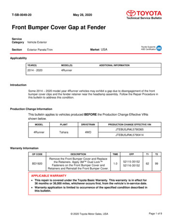
ster/IntroductionThis document provides instructions for the installation of a rear shock-absorbing bumper onto the RAMProMasterTM cargo van.This manual contains drawings and photos to aid in servicing the vehicle. It may include maintenanceinformation on some items installed but not manufactured by Utilimaster Corporation. Items suchas drivetrain components and certain interior furnishings may be covered by separate manufacturersupplied information. Information provided here is intended to assist Utilimaster customers and is in noway meant to replace or supersede instructions provided by other suppliers for their products.Rear step bumper(White shown, reflective tape not included)ProMaster—Shock-Absorbing Bumper2
ster/Notes, Cautions, and WarningsReading through the procedures, you will see NOTES, CAUTIONS, andWARNINGS. Each is there for a specific purpose.NOTES give additional information that will help you complete the procedure.CAUTIONS warn against making an error that could damage the vehicle.WARNINGS remind you to be careful when there is risk of personal injury.When you see this symbol, read this statement first! This alert highlights information that mayreduce the risk of personal injury or vehicle damage.Below are some basic WARNINGS that you should heed when you work on the vehicle’s body. Theyare not all-inclusive and common sense must be used when servicing vehicles. Always read and understand all instructions before starting. Always wear safety glasses and other appropriate protective equipment (gloves, steel-toedshoes, face shields, knee pads, hearing protection). Put the transmission in Park, and set the parking brake before working on the vehicle. Be sure that the ignition switch is Off unless otherwise required by the procedure. Keep your hair, clothing, and body away from all moving parts such as engine pulleys andpower tools. Always remove rings, watches, hanging jewelry, and loose clothing before working in tightareas. Read and understand all warning labels. Always use proper ladders or scaffolding to perform required jobs. Always make sure tools are in proper working condition and have guards and safety devicesin place. Use only the recommended tools for a specific job. If at any time you lack confidence in performing a specific repair procedure or in operatingthe tools safely to perform the repair, STOP! Call your local dealer or a ing Bumper3
ster/Recommended ToolsWARNING: Always wear safety glasses and other proper protective equipment (gloves, steel-toedshoes, face shields, knee pads, hearing protection) as appropriate to the process.Below are some tools that you will need for this process. There may be other commonly used handtools required but not specifically mentioned. Grease gun and greaseBlack and/or white touch-up paintRight angle drill with 1/2" step bitDrill with H (or 1/4") bitReciprocating sawPneumatic air hammerAngle GrinderStandard and metric combination and ratchet wrench sets including swivel adapter andextensionsTorque wrenches (ft lb increments)Kit Parts ListQTY1101905421SKPART ORBING BUMPER BLACKDESCRIPTIONREAR STEP BUMPER INSTRUCTIONSBUMPER FITZPATRICK PROMASTER VAN BLACKQTY1101905433SKPART ORBING BUMPER WHITEDESCRIPTIONREAR STEP BUMPER INSTRUCTIONSBUMPER FITZPATRICK PROMASTER VAN WHITENOTE: Each kit includes: Step bumper (1) Bumper frame mounts (2) Shock-absorbing struts (2) Toe kick angle (1) 7/16 x 5" bolts, locknuts, and flat washers (2) 1/2" x 1.5" bolts, washers and nuts (14) 1/4-20 bolts, washers and nuts (3) M10 bolts, washers and nuts (6)ProMaster—Shock-Absorbing Bumper4
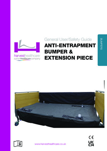
r.comInstallation Instructions1. Read and understand all instructions before starting work.2. Validate the packing slip with the list of parts in the instructions.NOTE: Keep all hardware and fasteners for reuse unless noted otherwise.3. Remove (8) screws from the bumper cladding and set aside.Bumper cladding4. Remove (4) bolts and (2) nuts from the bumper.Bumper bolts located behind rear crossbarProMaster—Shock-Absorbing Bumper5
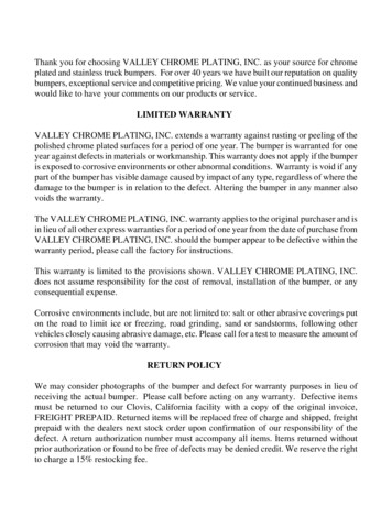
r.com5. Use an angle grinder and pneumatic air hammer to remove (2) weldbolts in the bumper.Bumper weldbolt removal6. If needed, use a reciprocating saw to remove stud on the LH frame rail.7. Use a reciprocating saw to remove tow hook on the RH rear crossbar and discard.Stud on LH frame railRH tow hook removal8. Deburr and paint exposed steel surfaces.9. If needed, use a 1/2" step bit and a right-angle drill to enlarge the hole in the chassis frame railsfor the bumper frame mounts.Enlarge hole in frame rail if necessaryProMaster—Shock-Absorbing Bumper6
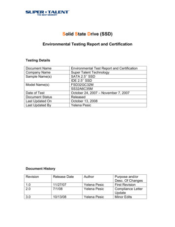
r.com10. Secure each bumper frame mount on the inboard side of the chassis frame rail using (1) 7/16 x5" bolts, locknuts, and flat washers. Do NOT tighten at this time.Position bumper frame mounts on the inboard side of chassis frame rails (RH shown)11. Install the bumper to the bumper frame mounts using (6) M10 bolts with (4) washers and nuts onlower holes.M10 fasteners for lower holes12. Torque bolts to 48 ft lb.13. Secure (8) screws in the bumper cladding.Bumper claddingProMaster—Shock-Absorbing Bumper7
r.com14. Install each shock absorbing strut on the inboard side of the bumper frame mounts with (3) 1/213 x 1.5" bolts, flat washers, and locknuts. Do NOT tighten at this time.Shock absorbing strut fasteners (RH shown)WARNING: Always support the bumper to keep it from falling.15. Use an H-bit to drill (3) holes spaced evenly across the width of the toe kick angle and bumper.16. Deburr and paint holes.17. Secure toe kick angle with (3) 1/4-20 bolts, washers and nuts.ABToe kick angle (A) and bumper (B)ProMaster—Shock-Absorbing Bumper8
r.com18. Secure rear step bumper to shock absorbing struts with (8) 1/2-13 x 1.5" bolts, washers and nuts.Bumper to shock absorber fasteners19. Use a tape measure to align bumper with bumper cladding.Align bumper20. Torque all 1/2" nuts on shock absorbing struts to 85 ft lb.21. Lubricate struts using approximately 6.5–7.5 grams (or five hand pumps) of #2 grease.Strut grease fittingsProMaster—Shock-Absorbing Bumper9
ster/Load Carrying Modification LabelNOTICE: Load Carrying Modification Label may be required to satisfy the statutoryrequirements for labeling contained in Title 49 of the United States Code, Chapter 5 (MotorVehicle Safety) and regulatory requirements contained in 49 CFR Parts 567 (Certification)and 568 (Vehicles Manufactured in Two or More Stages). A person who alters a vehicle thatpreviously has been certified in accordance with 49 CFR 571.110 may require an alteredcertification obligation. Altered certification regulations cover all manufacturing performedafter the vehicle has been certified in the final stage and before the first purchase of thevehicle in good faith for purpose other than resale.If you have any questions regarding labeling requirements or need to order labels, call NTEAat 1-800-441-6832.1. Fill out and apply the Load Carrying Modification Label as required.ProMaster—Shock-Absorbing Bumper10
ster/Revision ControlDocument Part Number: 03104592-N015ENRevision: ARevision: BRevision: CApril 2014September 2014June 2016Important Notices 2014, Utilimaster Corp. Title: ProMaster—Shock-Absorbing BumperUtilimaster Corporation attempts to provide information that is accurate, complete, and useful. Allinformation contained in this manual is based on the latest product information available at the time ofpublication. However, because of the Utilimaster policy of continual product improvement, Utilimasterreserves the right to amend the information in this document at any time without prior notice.This material is confidential and the property of Utilimaster. It is shared with your company for the solepurpose of helping you with the operation of the described equipment.Utilimaster makes no warranty of any kind with regard to this material, including, but not limited to, theimplied warranties of merchantability and fitness for a particular purpose. Utilimaster shall not be liablefor errors contained herein or for incidental or consequential damages in connection with the furnishing,performance, or use of this material.Utilimaster expressly disclaims all responsibility and liability for the installation, use, performance,maintenance, and support of third-party products. Customers are advised to make their independentevaluation of such products.No part of this document may be photocopied, reproduced, or translated to another language without theprior written consent of Utilimaster.Utilimaster is a registered trademark of Spartan Motors USA, Inc. All other products or name brandsmentioned in this document are trademarks of their respective owners.Browse our web site www.utilimaster.com for more information about Utilimaster and its products.Utilimaster Corp., 603 Earthway Blvd., Bristol, Indiana 46507-9182 USA ProMaster—Shock-Absorbing Bumper11
10. Secure each bumper frame mount on the inboard side of the chassis frame rail using (1) 7/16 x 5" bolts, locknuts, and flat washers. Do NOT tighten at this time. Position bumper frame mounts on the inboard side of chassis frame rails (RH shown) 11. Install the bumper to the bumper frame mounts using (6) M10 bolts with (4) washers and nuts on