Transcription
Articlepubs.acs.org/JACS2D Homologous Perovskites as Light-Absorbing Materials for SolarCell ApplicationsDuyen H. Cao,† Constantinos C. Stoumpos,† Omar K. Farha,†,‡ Joseph T. Hupp,†and Mercouri G. Kanatzidis*,††Department of Chemistry and Argonne-Northwestern Solar Energy Research (ANSER) Center, Northwestern University, 2145Sheridan Road, Evanston, Illinois 60208, United States‡Department of Chemistry, Faculty of Science, King Abdulaziz University, Jeddah 21589, Saudi ArabiaS Supporting Information*ABSTRACT: We report on the fabrication and properties of thesemiconducting 2D (CH3(CH2)3NH3)2(CH3NH3)n 1PbnI3n 1 (n 1,2, 3, and 4) perovskite thin films. The band gaps of the series decreasewith increasing n values, from 2.24 eV (CH3(CH2)3NH3)2PbI4 (n 1)to 1.52 eV CH3NH3PbI3 (n ). The compounds exhibit strong lightabsorption in the visible region, accompanied by strong photoluminescence at room temperature, rendering them promising lightabsorbers for photovoltaic applications. Moreover, we find that thinfilms of the semi-2D perovskites display an ultrahigh surface coverageas a result of the unusual film self-assembly that orients the [PbnI3n 1] layers perpendicular to the substrates. We have successfullyimplemented this 2D perovskite family in solid-state solar cells, andobtained an initial power conversion efficiency of 4.02%, featuring anopen-circuit voltage (Voc) of 929 mV and a short-circuit current density(Jsc) of 9.42 mA/cm2 from the n 3 compound. This result is even more encouraging considering that the device retains itsperformance after long exposure to a high-humidity environment. Overall, the homologous 2D halide perovskites define apromising class of stable and efficient light-absorbing materials for solid-state photovoltaics and other applications. system13,14 as well as in the mixed-metal CH3NH3Sn1 xPbxI3system.15 17 The moisture instability of MAPbI3 however hasbeen poorly addressed. Recently, Smith et al. reported the solarcell application of a layered (PhC2H5NH3)2(CH3NH3)2Pb3I10perovskite light absorber with enhanced moisture stability.18From a fundamental point of view, efficient externalluminescence is an indirect indication of accessing the highestpossible open-circuit voltage, a major factor in the total poweroutput aside from the short-circuit current and fill factor.19,20The 2D A2MI4-based perovskite compounds, where M is adivalent group 1421 or lanthanide22 metal, have been reportedto display high photoluminescence (PL) at room temperature,and up until now, they have been employed in field-effecttransistor (FET)23 and light-emitting diode (LED) devices.24,25To move from the 3D to the 2D perovskites, the small MA cation is replaced by a much bulkier organic primaryammonium cation, thus confining the perovskite in twodimensions because of steric effects. With these considerationsin mind, we turned our attention toward the multilayeredperovskite compounds, (A)2(CH3NH3)n 1MnI3n 1, and theirpotential as light-absorbing materials, where the bulkyINTRODUCTIONThe emergence of hybrid halide perovskite compounds, AMX3(A Cs , CH3NH3 , or HC(NH2)2 ; M Sn2 and Pb2 ; andX Cl , Br , and I ), in solid-state solar cells has triggered aphenomenal advance in the photovoltaic efficiency in the lastthree years.1 6 Perovskite compounds, in the form ofCH3NH3PbX3, were originally employed as light-absorbingmaterials in liquid dye-sensitized solar cells by the Miyasakagroup.7 However, they did not engender a lot of attentionbecause of short device lifetime resulting from the fastdissolution of perovskites in the redox electrolyte solution.Three years later, we have witnessed the return of perovskitebased solar cells in a different fashion: solid-state.2,8 Thephotovoltaic performance race has been remarkable ever since,and an efficiency of 20.1% has been certified by NREL.9,5Among the light absorber candidates, 3D methylammonium(MA) lead iodide (MAPbI3) is the most prominent choiceowing to its outstanding properties for a solar cell absorber,including a high extinction coefficient,10 a medium band gap,11a small exciton binding energy, and long exciton and chargediffusion lengths.12 From a commercialization point of view, thelarge-scale implementation of perovskite solar cells requirestoxicity and stability issues to be resolved. Recently, works ontin-based perovskites have been reported, demonstrating apromising efficiency of ca. 5% for the CH3NH3SnI3 xBrx 2015 American Chemical SocietyReceived: April 13, 2015Published: May 28, 20157843DOI: 10.1021/jacs.5b03796J. Am. Chem. Soc. 2015, 137, 7843 7850
ArticleJournal of the American Chemical Societyammonium (the spacer) and methylammonium (the “perovskitizer”) cations are employed simultaneously.2D multilayered halide perovskites take the generic structuralformula of (A)2(CH3NH3)n 1MX3n 1 (n is an integer), where Ais a primary aliphatic or aromatic alkylammonium cation, M is adivalent metal, and X is a halide anion. The 2D networkconsists of inorganic layers of corner-sharing [MX 6 ] 4 octahedra confined between interdigitating bilayers of intercalated bulky alkylammonium cations.26 The unit layers arestacked together by a combination of Coulombic andhydrophobic forces to maintain the structure integrity. These2D compounds could be regarded as natural multiple-quantumwell structures in which the semiconducting inorganic layers actas “wells” and the insulating organic layers act as“barriers”.24,27,28In this article, we report on the fabrication and properties ofthin films of the 2D lead iodide perovskite(CH3(CH2)3NH3)2(CH3NH3)n 1PbnI3n 1 series, which combines the structural features of the simple 2D (n 1) and the3D (n ) perovskites. We then show that the thin filmsremarkably, grow with the [PbnI3n 1] slabs perpendicular to thesubstrates and as a result can be used as the light-absorbinglayer to fabricate functional solar cells. We establish here thatunlike 3D MAPbI3 which requires more complex filmfabrication methods to achieve high-quality films,3,29,30 the2D analogues yield smooth, ultrahigh surface coverage filmsfrom a simple one-step spin-coating approach. In addition, 2Dperovskite-based films are notably moisture-resistant. In thiswork, our best power conversion efficiency of 4.02% wasobtained by using (CH3(CH2)3NH3)2(CH3NH3)2Pb3I10 as alight absorber, with an open-circuit voltage (Voc) of 929 mVand a short-circuit current (Jsc) of 9.42 mA/cm2. precursors. For planar structure, the ALDed TiO2 substrates weresoaked in a 0.1 M aqueous solution of TiCl4 for 30 min at 70 C,rinsed with deionized water, and dried at 500 C for 20 min. Forsensitized structure, a mesoporous TiO2 layer composed of 20 nmparticles was deposited on the ALD-treated TiO2 substrates by spincoating at 4000 rpm for 30 s using a commercial TiO2 paste (Dyesol18NR-T) diluted in anhydrous ethanol (2:7 weight ratio).Mesoporous TiO2 substrates were then gradually annealed by heatingfrom room temperature to 500 C (8 C/min) for 15 min, followed bypost-treating in a 0.1 M aqueous solution of TiCl4 for 30 min at 70 C.The TiO2 substrates were finally rinsed with deionized water and driedat 500 C for 20 min. The light-absorbing layers were deposited byspin-coating 1.8 M Pb2 perovskite precursor solutions at 3000 rpm for30 s. The 1.8 M Pb 2 precursor solutions of MAPbI 3 ,(BA)2(MA)n 1PbnI3n 1 (n 4, 3, 2, and 1) were prepared bydissolving the corresponding amount of perovskite powders inanhydrous dimethylformamide (DMF) solvent with stirring at 70 Cfor 30 min prior to film deposition. MAPbI3 film was formed afterannealing in air at 100 C for 15 min, whereas other 2D perovskitefilms were formed immediately after spin-coating at room temperature.The spiro-OMeTAD hole-transporting material (HTM) solution,comprised of 65.3 mM spiro-OMeTAD, 9.1 mM lithium bis(trifluoromethanesulfonyl)imide, and 93.8 mM 4-tert-butylpyridine inchlorobenzene solvent, was then deposited on the perovskite layer byspin-coating at 4000 rpm for 30 s. Films were dried under vacuumovernight before completing the device fabrication process by thermalevaporating 80 nm of gold on top of the HTM layer. RESULTS AND DISCUSSIONFilm Fabrication and Film Growth Characteristics. The2D (CH3(CH2)3NH3)2(CH3NH3)n 1PbnI3n 1 family of perovskite compounds (n 1 4) was synthesized from astoichiometric reaction between PbI2, MAI, and n-butylammine(BA). Structurally, the 2D perovskites are the product of slicingthe 3D perovskite along the (110) plane, in such a way thatsome of the oriented MA cations are partially (n 2, 3, and 4)or fully (n 1) substituted by BA cations.24 More details of thesynthesis and an in-depth study of crystal structures, physical,and optical properties of the 2D perovskite family will bereported separately.The incorporation of perovskite light absorber into afunctional solid-state solar device requires the transformationof perovskite powder materials into thin films. In this work, allperovskite films were fabricated by a one-step depositionmethod, by means of spin-coating the DMF precursor solutionsof perovskite on mesoporous TiO2 substrates. The well-studiedMAPbI3 xClx film was also prepared for comparison purposes.2To fabricate MAPbI3 xClx film, the precursor solution wasprepared by mixing a 3:1 molar ratio of MAI and PbCl2 inDMF. Deposition of the MAPbI3 film by the one-step approachhas been shown to produce low-quality films that suffer fromlow surface coverage and large, nonuniform crystal size,resulting in low conversion efficiency. Therefore, many differentapproaches of film deposition have been examined to improvethe film quality, including high-vacuum vapor deposition,sequential deposition, vapor-assisted deposition, solvent engineering, etc.29,3,30,4 Conversely, in this work we observe highquality 2D perovskite films can be easily formed using the onestep method. The 2D perovskites self-assemble to form welldefined films on the substrates with nearly perfect surfacecoverage and a fine texture. The growth of the films is clearlydriven by the 2D nature of the compounds forming highlyoriented crystals with only a few grain boundaries. Interestingly,the 2D films are readily formed immediately after the spincoating process without requiring annealing steps, demonstrat-EXPERIMENTAL SECTIONMaterials. 9′spirobifluorene (spiro-OMeTAD) was purchased from FeimingChemical Limited. Transparent titania (TiO2) paste (Dyesol 18NRT) was purchased from DyeSol. All other chemicals were purchasedfrom Sigma-Aldrich. Unless otherwise stated, all were used as received.Methylammonium iodide (MAI) was synthesized by neutralizingequimolar amounts of a 57% w/w aqueous hydriodic acid (HI) and40% w/w aqueous methylamine (CH3NH2, pH 7). The whiteprecipitate was collected by evaporation of the solvent using rotaryevaporation at 60 C under reduced pressure.Synthesis. PbO powder was dissolved in a mixture of 57% w/waqueous HI solution and 50% aqueous H3PO2 by heating to boilingunder constant magnetic stirring for about 5 min, forming a brightyellow solution. Subsequent addition of solid CH3NH3I to the hotyellow solution initially caused the precipitation of a black powder thatrapidly redissolved under stirring to afford a clear bright-yellowsolution. n-CH3(CH2)3NH2 was then added dropwise under vigorousstirring over a period of 1 min without any changes in the solution.The stirring was then discontinued, and the solution was left to cool toroom temperature during which time deep-red rectangular-shapedplates started to crystallize. The precipitation was deemed to becomplete after 2 h. The crystals were isolated by suction filtrationand thoroughly dried under reduced pressure.Device Fabrication. FTO-coated glass (1.5 cm 2.0 cm, TEC 7,2.2 mm, Hartford Glass Co., Inc.) was patterned by etching away a 5mm strip with zinc powder and 4 M HCl. Then, substrates werecleaned by sonication in detergent, isopropanol, acetone, and driedunder an air flow before use. A 20 nm thick TiO2 compact layer wasdeposited onto the substrates by atomic layer deposition (ALD;Savannah S300, Cambridge Nanotech Inc.) using titanium isopropoxide (0.15 s pulse time, 8 s exposure time, and 20 s purge time) andwater (0.015 s pulse time, 8 s exposure time, 20 s purge time) as7844DOI: 10.1021/jacs.5b03796J. Am. Chem. Soc. 2015, 137, 7843 7850
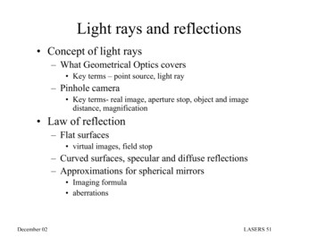
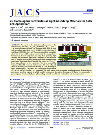
ArticleJournal of the American Chemical SocietyGenerally, the orientation of 2D materials on flat substratesstrongly favors growth where the layers orient parallel to thesubstrate, a trend that has also been observed in the case ofsingle-layer halide perovskites. 3 1 In the case of(BA)2(MA)n 1PbnI3n 1, this trend appears to be true only forthe n 1 compound, where preferential growth along the (110)direction occurs, thus exclusively revealing the (00l) reflections.As soon as the layers become thicker (n 1), a competitionarises between the BA ions, which try to confine the growthwithin the planar layer, and the MA ions, which try to expandthe perovskite growth outside the layer. Already for the n 2compound, the (0k0) reflections are “contaminated” with the(111) and (202) reflections, which reveal the vertical growth ofthe compound with respect to the substrate plane. (Note thatthe (0k0) reflections for n 2 4 correspond to the (00l)reflection for n 1 and .) The n 3 and 4 compoundscontinue the trend by showing exclusively the (111) and (202)reflections and lacking (0k0) reflections, clearly indicating thevertical growth of the perovskite compounds. This effectbecomes even more pronounced when one compares it withthe preferential growth of the bulk (BA)2(MA)n 1PbnI3n 1compounds (Figures 1 and 2). These appear to follow thestandard norms (crystallizing along the (h0l) plane), therebyshowing only the (0k0) reflections. We reason that the (111)reflection dominates the diffraction patterns because the (101)reflection is not allowed (h 2n and h, l 2n reflectionconditions); therefore, the closest plane describing the verticalgrowth becomes the (111) plane.ing a facile preparatory method and rendering it compatiblewith flexible substrates.The thin films of (BA)2(MA)n 1PbnI3n 1 perovskites show ahighly remarkable tendency when the orientation of thestructure on the substrate is considered (Figures 1 and 2).Figure 1. XRD of thin films vs bulk materials of (a) BA2PbI4 and (b)MAPbI3 perovskites, with the illustration of their respective diffractionplanes. In b, films of MAPbI3 correspond to the unique and ideal caseof perfect orientation obtained from the 3D MAPbI3 xClx system.Figure 2. XRDs of thin films vs bulk materials of (a) (BA)2(MA)Pb2I7, (b) (BA)2(MA)2Pb3I10, and (c) (BA)2(MA)3Pb4I13 perovskites, with theillustration of their respective diffraction planes. Note that the Miller indices are different from those of (BA)2PbI4 and MAPbI3 because of thedifferent assignment of the orthogonal unit cell axes.7845DOI: 10.1021/jacs.5b03796J. Am. Chem. Soc. 2015, 137, 7843 7850
ArticleJournal of the American Chemical Societyattributed to the hydrophobicity of the long BA cation chainand the highly oriented and dense nature of the perovskitefilms, which prevent direct contact of adventitious water withthe perovskite.Optical Properties. For convenience, in the present andforthcoming sections, we will abbreviate MAPbI3 as PbI3, andthe 2D series as Pb4I13, Pb3I10, Pb2I7, and PbI4 when n is equalto 4, 3, 2, and 1, respectively. Previously, in our work on twostep sequentially deposited films of PbI3, we observed someunusually broad absorption edges lying between the band edgesof PbI2 (2.4 eV) and PbI3 (1.5 eV).32 We speculated theseabsorption characteristics were due to incomplete conversion ofPbI2, leading to the formation of intermediate layeredcompounds that were stabilized by surface effects on the thinfilms. We investigated the optical properties of the series inboth bulk and thin film samples. The optical band gaps (Eg) inthe (BA)2(MA)n 1PbnI3n 1 series increase with decreasedthickness of the inorganic slabs from 1.52 eV (n ) to2.24 eV (n 1) because of quantum confinement effects fromthe dimensional reduction of the perovskite chromophore.33 35In addition to the primary absorption edge, we observedanother peak above the absorption edge region appearing in the2D perovskites. The intensity of the second peak is strongestfor the n 1 compound and progressively subsides as thenumber of the inorganic slabs increases; it practically disappearsfor the n 4 compound (Figure 5a). This secondary absorptionis attributed to a long-lived excitonic state trapped in the strongelectrostatic field generated by the localized positively chargedBA ions around the negatively charged (MA)n 1PbnI3n 1layers.28 This local electric field provides sufficient chargescreening that inhibits the long-range separation of thephotogenerated electron hole pair, thus increasing itsrecombination probability. The excitonic binding energies ofthe layered perovskite series are thus expected to decrease withincreasing n (from 1 to ). The same behavior is also observedin the absorption spectra of the spin-coated TiO2 perovskitefilms of the compounds (Figure 5b), thus further validating thesuccessful deposition of the target compound onto thesubstrate. Interestingly, the absorption spectra of the purecompounds are in good agreement with those of theintermediate absorption spectra observed in the two-stepdeposited MAPbI3,32 an observation that hints toward thepossibility of the formation of layered-like intermediates duringthe formation of the 3D perovskite films that are stabilized bythe TiO2 surfaces.As is well-demonstrated, thin films of both the 2D PbI4 and3D PbI3 compounds display PL at room temperature(RT).24,36,37 We have sought to confirm this property byperforming PL measurements on the (BA)2(MA)n 1PbnI3n 1homologous perovskite series on films deposited onto glasssubstrates. Indeed, we observe RT PL from all 2D perovskitesas shown in Figure 5c. The PL spectra of all four 2Dcompounds and the 3D analogue have distinct features that arefully consistent with the experimentally determined opticalband gaps. A very strong PL emission is observed for the n 1compound; the emission wavelength corresponds to the highenergy absorption peak (bound exciton), and it lies above theground state of the band gap. Interestingly, when additionalslabs are introduced (increasing n), the PL emission energyshifts in each case according to the low-energy absorption peak(free exciton) and applies to the n 2, 3, and 4 compounds.The efficient external luminescence observed in the compoundsis a highly desirable property for photovoltaic applicationsThe extremely well oriented (BA)2(MA)n 1PbnI3n 1 perovskite films are already superior to MAPbI3 films deposited bythe crude one-step method, and their quality is alreadycomparable to the best-oriented MAPbI3 films obtained bymeans of the superior “mixed-halide” MAPbI3 xClx method(Figure 1b).2 The successful vertical crystal growth of the 2Dperovskites on the substrate is further confirmed by thescanning electron microscopy (SEM) images, exemplified inthe form of Pb3I10 films. Figure 3d shows extremely well-Figure 3. (a and b) Top surface and (c and d) cross-sectional SEMimages of MAPbI3 and (BA)2(MA)2Pb3I10 on TiO2 films.packed, vertically oriented crystallites displaying excellentsurface coverage. Vertical growth is highly desirable inphotovoltaic devices because it facilitates charge transportalong the Pb I Pb pathway to the electron- and holeaccepting contacts. Additionally, the evolution of continuouscrystallites with few crystal boundaries promises significantimprovement in the carrier transport mobility.Another favorable property of the 2D perovskite films thatalso benefits their potential technological exploitation is theirextremely high moisture stability. As an example, a film ofMAPbI3 gradually decomposed to yellow PbI2 after a short timein moist atmosphere because of the gradual loss of the MA cation (Figure 4b). However, a film of (BA)2(MA)2Pb3I10remained unchanged after 2 months exposure under a 40%humidity condition. The stability of the film was additionallyconfirmed by XRD (Figure 4a), in which no PbI2 peak wasobserved in the 2 month old (BA)2(MA)2Pb3I10 film. Themoisture-resistant property of the 2D perovskites may beFigure 4. (a) XRDs of fresh and aged (2 months) (BA)2(MA)2Pb3I10film. (b) Images of five different perovskite films before and afterexposure to humidity.7846DOI: 10.1021/jacs.5b03796J. Am. Chem. Soc. 2015, 137, 7843 7850
ArticleJournal of the American Chemical Societygrowth characteristics that offer tremendous potential forsuccessful implementation in solar cells. We thus proceeded toassemble and characterize photovoltaic devices. Initial attemptsyielded a promising, high Voc from devices of the semiconducting 2D Pb3I10 compound. Hence, we followed up byexploring two different aspects: (i) changing the devicestructure from planar (TiO2 compact layer only) to sensitized(250 1100 nm mesoporous TiO2) and (ii) changing theperovskite precursor concentration (0.9, 1.8, 2.7, and 3.6 M,based on the total Pb2 content). The photovoltaic responses ofall fabricated devices can be found in Supporting Informationsection S7. The side view of typical TiO2-deposited 2Dperovskite films prior to the HTM deposition step are shown inFigure 6.Our champion first-generation 2D device was obtained fromthe Pb3I10 light absorber in combination with a 350 nm TiO2mesoporous film and 1.8 M perovskite concentration. (SeeFigure S4 for cross-sectional SEM image of a complete device.)Under AM 1.5G solar illumination, the photogenerated Voc was929 mV, and Jsc was 9.43 mA/cm2 , ultimately yielding aconversion efficiency η of 4.02% as shown in Figure 7 andFigure 7. J V curves of sensitized lead iodide perovskite-based solarcells.Table 1. Photovoltaic Performances of Sensitized LeadIodide Perovskite-Based Solar CellsFigure 5. Optical band gaps of (a) bulk, (b) spin-coated TiO2 perovskite thin films, and (c) PL spectra of spin-coated glass perovskite thin films of the MAPbI3 and (BA)2(MA)n 1PbnI3n 1compounds.because it is an indirect indication of efficient carrier generation,thus granting access to the highest possible open-circuitvoltage.19Device Fabrication and Photovoltaic Performance. Asstated in the previous section, the properties of the(BA)2(MA)n 1PbnI3n 1 perovskite films show unique filmdeviceJsc (mA/cm2)Voc (mV)FF (%)efficiency 7304633292.412.394.020.390.01Table 1. The performance of the PbI3 device, prepared underidentical conditions, was lower than that of the currentchampion device.5 We attribute this difference mainly to thehigh concentration of PbI3 precursor and the one-stepFigure 6. Cross-sectional SEM images of TiO2 perovskite films prepared from 1.8 M Pb2 precursors, showing preferentially oriented film growth of2D perovskite compounds.7847DOI: 10.1021/jacs.5b03796J. Am. Chem. Soc. 2015, 137, 7843 7850
ArticleJournal of the American Chemical Societythan those based on PbI3) seems particularly promising andcould bode well for incorporation of the material in morecomplex structures, e.g., the top cell in a tandem solar cell.39,40For PbI3-based solar cells, it has been shown that photogenerated excitons dissociate into free charges within theperovskite, regardless of whether electron- and/or holeaccepting layers are present.12,41 The observed Voc of thePb3I10-based device is in line with what might be anticipatedfrom the HTM HOMO and the TiO2 CB edge energy, but it isonly half that of the Pb3I10 bandgap. Replacement of theelectron- and hole-accepting materials with ones much bettermatched to the Pb3I10 (or Pb4I13) VB and CB edge energiesmay yield substantially higher open-circuit photovoltageswithout undue penalties for short-circuit photocurrents. Thisis under investigation in our laboratory, and the findings will bereported separately.With Pb3I10 demonstrating the best conversion efficiency, wefurther investigated the photoresponses of this compound. Inparticular, we investigated the performances of cells containingplanar versus nanoparticulate electron-accepting layers devicestructures (for simplicity, we will refer to the latter as sensitizeddevices). We prepared planar devices with increasingthicknesses of the perovskite light-absorber layer by means ofincreasing the precursor concentration from 0.9 to 3.6 M ofPb2 . As can be seen in Figure 9, the Jsc of planar devices aredeposition method. We intentionally used this method to keepthe device fabrication process constant between the 3D and 2Dmaterials in order to properly evaluate the resulting devices.Our approaches for the fabrication of high-efficiency PbI3devices have been reported elsewhere.32,38 The Jsc obtainedfrom Pb4I13 is similar to that of Pb3I10, but the Voc and the FFare significantly lower, resulting in a substantially lowerconversion efficiency. With Pb4I13 having a lower Eg thanPb3I10, we anticipated that the Pb4I13-based device would attaina higher Jsc. However, other factors may influence the overalldevice performance. For instance, Figure 6 shows a thinnerPb4I13 film formed compared to that formed by Pb3I10, eventhough films were prepared from the same concentration ofprecursor solution (1.8 M Pb2 ). One possible explanation forthis is that the smaller amount of light-absorbing materialabsorbs less light and generates less photocurrent, yielding alower Jsc. The other two compounds of the 2D series, Pb2I7 andPbI4, produce significantly less current than those of the higher2D members with thicker inorganic slabs, plausibly because oftheir much higher optical band gaps and their less favorable filmgrowth characteristics for charge transport. Specifically, Pb2I7film grows in both (0k0) and (111) orientations, and PbI4 filmgrows parallel to its substrate, along the (00k) plane.To gain better insight into the charge transport dynamics inthe 2D perovskite devices, we determined the position of thevalence band maxima (VBM) of all five (BA)2(MA)n 1PbnI3n 1perovskite compounds, via ultraviolet photoelectron spectroscopy (UPS). The conduction band (CB) minima weredetermined by subtracting the VBM from the correspondingEg. As can be seen in Figure 8, the VBM increases withFigure 9. J V curves of planar (BA)2(MA)2Pb3I10-based devices.very low despite the presence of a thick perovskite layer ( 600nm for 1.8 M). In addition, both Jsc and Voc gradually decreasewhen the light-absorber layer gets thicker. This observationimplies that the overwhelming majority of photogeneratedelectrons are unable to diffuse through the thick perovskitelayer to reach the TiO2 electron-acceptor interface. Conversely,when a mesoporous TiO 2 layer is introduced, J sc istremendously enhanced. This is an indication that the charge(electron) diffusion length of Pb3I10 is likely shorter than that ofPbI3 because the planar device structure of PbI3 has beensuccessfully implemented elsewhere.30 Nonetheless, the planardevice structure offers significantly better FF, suggesting thatthe semiconducting 2D Pb3I10 material itself possesses highcarrier mobility. It is noticeable that the fill factor (FF) of 2Dsensitized-devices is somewhat lower than those of 2D planarand 3D devices. This low FF value is an indication of highseries resistance (Rs), which can be attributed to the suboptimalcrystallinity of perovskites inside the mesoporous TiO2 layerand the charge-transport resistance at the interface ofmesoporous TiO2 and perovskite. Predictably, the low FF canbe overcome by replacing the current charge-selective contactswith the more compatible candidates.It is remarkable that the sensitized device structure of Pb3I10functions well despite having a thick ( 1000 nm) perovskiteFigure 8. Comparative band energy diagram of the(BA)2(MA)n 1PbnI3n 1 perovskite compounds.decreased dimensionality, from PbI3 (5.46 eV) to PbI4 (4.55eV). The CB energy edges of all five perovskite compounds arehigher than that of the TiO2 electron acceptor, whichtheoretically would allow electron injection from the lightabsorbing materials to TiO2 unless the charge recombinationprocess happens at a faster rate. Although it is favorable forholes generated from PbI3, Pb4I13, and Pb3I10 to hop into thespiro-OMeTAD hole-transporter, this step is inhibited withPb2I7 and PbI4 because their VBM energy levels are higher thanthe HOMO level of spiro-OMeTAD. Therefore, the probabilityof the photogenerated electrons and holes recombining ishigher in Pb2I7 and PbI4, which essentially lowers theirphotocurrent densities.The routine observation of Voc in excess of 900 mV fromcells based on the semi-2D Pb3I10 compound ( 200 mV higher7848DOI: 10.1021/jacs.5b03796J. Am. Chem. Soc. 2015, 137, 7843 7850
ArticleJournal of the American Chemical Societyluminescence at room temperature, pointing to their potentialfor use in light-emitting diodes. Films of 2D compounds areformed in a self-assembly fashion with preferentially orientedgrowth perpendicular to the substrate, favoring charge transportand providing essential access to ultrasmooth and high-surfacecoverage thin films. An additional benefit of using large organiccations in the 2D films is moisture resistance that is greatlyenhanced compared to that of their 3D MAPbI3 analogue,making them more attractive for large-scale industrialimplementation. Our best first-generation 2D device isobtained from the semi-2D (BA)2(MA)2Pb3I10 light absorberunder the sensitized device structure, which yields a solar-toelectricity conversion efficiency of 4.02%. Work in progress isdirected toward improving charge diffusion length of theperovskite light-absorbing materials via synthesis routes as wellas device parameters such as the fill factor and open-circuitphotovoltage loss by exploring more compatible electron- andhole-carrier layers in both planar and sensitized devicestructures.capping layer on top of the TiO2 mesoporous layer. It is certainthat the light absorber infiltrated in the mesoporous TiO2contributes
2D Homologous Perovskites as Light-Absorbing Materials for Solar Cell Applications Duyen H. Cao,† Constantinos C. Stoumpos,† Omar K. Farha,†,‡ Joseph T. Hupp,† and Mercouri G. Kanatzidis*,† †Department of Chemistry and Argonne-Northwestern Solar Energy Research (ANSER) Center, Northwestern University, 2145 Sheridan Road, Evanston, Illinois 60208, United States