Transcription
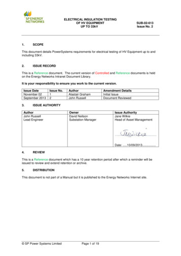
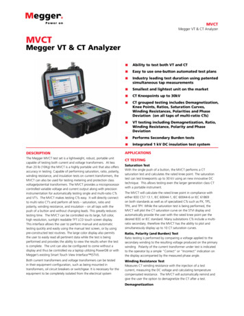
MVCTMegger VT & CT AnalyzerMVCTMegger VT & CT Analyzer Ability to test both VT and CT Easy to use one-button automated test plans Industry leading test duration using patentedsimultaneous tap measurements Smallest and lightest unit on the market CT Kneepoints up to 30kV CT grouped testing includes Demagnetization,Knee Points, Ratios, Saturation Curves,Winding Resistances, Polarities and PhaseDeviation (on all taps of multi-ratio CTs) VT testing including Demagnetization, Ratio,Winding Resistance, Polarity and PhaseDeviation Performs Secondary Burden tests Integrated 1 kV DC insulation test systemDESCRIPTIONAPPLICATIONSThe Megger MVCT test set is a lightweight, robust, portable unitcapable of testing both current and voltage transformers. At lessthan 20 lb (10Kg) the MVCT is a highly portable unit that also offersaccuracy in testing. Capable of performing saturation, ratio, polarity,winding resistance, and insulation tests on current transformers, theMVCT can also be used for testing metering and protection classvoltage/potential transformers. The MVCT provides a microprocessorcontrolled variable voltage and current output along with precisioninstrumentation for automatically testing single and multi-ratio CTsand VT’s. The MVCT makes testing CTs easy. It will directly connectto multi ratio CT’s and perform all tests – saturation, ratio andpolarity, winding resistance, and insulation – on all taps with thepush of a button and without changing leads. This greatly reducestesting time. The MVCT can be controlled via its large, full color,high resolution, sunlight readable TFT LCD touch screen display.This interface allows the user to perform manual and automatictesting quickly and easily using the manual test screen, or by usingpre-constructed test routines. The large color display also permitsthe user to easily read all pertinent data while the test is beingperformed and provides the ability to view the results when the testis complete. The unit can also be configured to come without adisplay and thus be controlled via a laptop utilizing PowerDB or withMegger’s existing Smart Touch View Interface (STVI).CT TESTINGBoth current transformers and voltage transformers can be testedin their equipment configuration, such as being mounted intransformers, oil circuit breakers or switchgear. It is necessary for theequipment to be completely isolated from the electrical systemWinding Resistance TestMeasures CT winding resistance with the injection of a testcurrent, measuring the DC voltage and calculating temperaturecompensated resistance. The MVCT will automatically remind andgive the user the option to demagnetize the CT after a test.Saturation TestWith the single push of a button, the MVCT performs a CTsaturation test and calculates the rated knee point. The saturationtest can test kneepoints up to 30 kV using an new innovative DCtechnique. This allows testing even the larger generation class CTwith a portable instrument.The MVCT will calculate the rated knee point in compliance witheither IEEE C57.13.1, IEC 60044-1, IEC 60044-6 or IEC 61869on both standards as well as of specialized CTs such as PX, TPS,TPX, and TPY. While the saturation test is being performed, theMVCT will plot the CT saturation curve on the STVI display andautomatically provide the user with the rated knee point per thedesired IEEE or IEC standard. Many substations CTs include a multiratio secondary; therefore the MVCT has the ability to plot andsimultaneously display up to 10 CT saturation curves.Ratio, Polarity (and Burden) TestRatio testing is performed by comparing a voltage applied to thesecondary winding to the resulting voltage produced on the primarywinding Polarity of the current transformer under test is indicatedto the operator by a simple “Correct” or “Incorrect” indication onthe display accompanied by the measured phase angle.Demagnetization
MVCTMegger VT & CT AnalyzerFEATURES AND BENEFITSNormal operating conditions and typical winding resistancemeasurements can cause a CT to become magnetized. TheMVCT offers the ability to automatically demagnetize the CTunder test or manually demagnetize the CT at any time. Prior totesting demagnification is recommended per ANSI C57.13.1. Thisdemagnetization routine ensures that the CT testing yields acurateresults Direct Connection to Multi Ratio CT’s - The MVCT will directlyconnect to all taps on multi ratio CT’s to eliminate lead changesrequired to test all inner-winding CT ratios, saturation curves andknee points. The MVCT will test all programmed taps with thepush of one button. Full Color, High Resolution, sunlight readable TFT LCDCT BurdenThe MVCT measures the connected CT burden load with directinjection of secondary current to a load that is disconnected fromthe CT. The MVCT measures the Secondary voltage in magnitudeand angle and reports the connected burden in VA and powerfactor.Touch Screen - Menu screens and touch screen functionbuttons are provided to quickly and easily select the desired testfunction. Tests results can be saved to the unit for download to amemory stick to transfer or print test reports. CT Saturation, Ratio and Polarity, Winding Resistance, andInsulation Automated Testing - The microprocessor-controlledoutput fully automates testing of CT’s. This automated testingsimplifies CT testing and reduces testing time. Automatedtesting is accomplished directly on the MVCT or via PowerDB Lite.INDUCTIVE VT TESTINGRatio, Polarity and Ratio with Burden TestAs part of a regular maintenance program to verify factory readingsand locate the presence of defects in voltage transformers, theMVCT can accurately measure the ratio, phase displacement, andsecondary winding resistance. The MVCT utilizes up to 300V toaccurately measure the ratio, phase angle of a VT VT Ratio and Polarity, Secondary Winding Resistance, andInsulation Testing - The MVCT offers complete testing of VT’s.The MVCT simplifies VT testing and reduces testing time. CT Demagnetization - During operation and routineDC winding resistance testing, it is possible for a CT tobecome magnetized. The MVCT includes an automated CTDemagnetization function, which allows determination ofaccurate Knee Point and ratios thus providing stable, repeatabletest results, and reduces test time.Winding Resistance TestMeasures VT secondary winding resistance with the injection of atest current, measuring the DC voltage and calculating temperaturecompensated resistance.Insulation Resistance TestIn order to ensure that the VT primary and secondary wiringis properly insulated, the MVCT system includes a 500/1000Vinsulation resistance test system. This insures that the secondaryinsulation has not degraded and will continue to perform itsfunction. Insulation Test - The MVCT includes a 500/1000V insulationtest system to verify the VT & CT secondary winding andsecondary wiring. This insures that the secondary insulation hasnot degraded and will continue to perform its function duringhigh current faults. Concurrent Measurement - The MVCT system can provideData Storage and PrintingThe MVCT test system not only permits accurate and automatedVT & CT testing, but also catalogues and stores test results withinthe instrument for simple retrieval by software at a later date. Allcatalogued test results can be uploaded to Megger’s PowerDBTM Litefor report generation and saturation curve plotting on a computeror STVI. PowerDB Lite also has the ability to operate the MVCT withno operator intervention, thus providing a completely computercontrolled automated test system.concurrent measurement of voltages on all taps during CTsaturation, and ratio and polarity testing. This allows the MVCTsystem to calculate the knee points, and ratios of all windingsat the same time thus eliminating the need for multiple testson a CT. This will drastically reduce testing time. All tests areperformed in compliance with IEEE C57.13.1 test guidelines. Test Result Report - The MVCT offers storage of complete testfiles in an easy-to-use, versatile format that permits upload toPowerDB Lite, or printing test results using the optional externalprinter. These options provide a simple, complete, easy way tostore over 1000 test results and saturation curves. All test resultscan be catalogued and stored in the MVCT.Onboard memory allows complete test results and data to be storedin one complete file, permitting easy access and quick constructionof reports such as saturation curves with knee point and ratios.2
MVCTMegger VT & CT AnalyzerTECHNICAL FEATURESWinding Resistance Test Automatic testing according to ANSI C57.13; IEC 60044-1; IECTest Amps60044-6; or IEC 61869-2 on Relaying/Protection Class CTs., andIEC 61869-3 on Inductive Voltage Transformers0.2 A DC, 0.5 A DCMeasuring Range 0.01Ω - 9.9Ω Excellent noise immunity from energized power lines inAccuracysubstations(at 20 C): 1% 2 digits (0 to 10 Ω)Insulation Test CT ratio and phase measurement with consideration ofTest Voltagenominal and connected burdens Primary currents from 1% to 200% of the rated value Various burdens of 1/8, ¼, ½, and full1000 VDC, 500 VDCMeasuring Range 20GΩShort CircuitCurrent1.5mA nominal CT & VT winding resistance measurementTest Current onLoad1mA at min. pass values of insulation (as specified inBS7671, HD 384 and IEC 364) Automatic demagnetization of CT after testAccuracy1000 volts 3% 2 digits 0.2% per GΩ Ratio accuracy to - 0.05%500 volts 3% 2 digits 0.4% per GΩ Decoupled demagnetization routine that can be performed atCommunication Interfacesany time.Ethernet Reduced Testing time with concurrent measurement of multi ratioUSBCTs Small and lightweight ( 20lb / 9.07kg )Environment Increased level of safety using low voltage DC methodsOperating-10º C to 50º C Remote control interfaceStorage-30º C to 70º C Easily configurable test plansEnclosure Customizable reportsThe unit is housed in a rugged enclosure suitable for use in outdoorsubstations. CT Knee point voltages up to 30kVStandardsIEC 61010CSA 22.2CE conformitySPECIFICATIONSInput100 to 265 V, 50 or 60 Hz, 10 A max.OutputsOutput VoltageOutput CurrentOutput PowerInputsRangesResolutionAccuracyDimensions0 to 300 V AC 0 to 300 V DC0 to 1 A eff300VA14” H X 7.5” W X 12” D(36 H X 19.3 W X 30.5 D cm)0 to 2/10/50/300 V0.0001 V 0.02% of readingand .02% range typical 0.05% of reading and 0.05% range maximumWeight20 lb (9.07 kg)Current MeasurementRange0 to 1.0 AResolution0.0001 AAccuracy 0.08% of reading .08% range typical 0.2% of reading 0.2% range maximumCT TESTINGRatioStandardOption RangeAccuracy0.8 to 2000 0.02% typical 0.05% maximum.2000 to 5000 0.03% typical 0.1%maximum.5000 to 20000 0.05% typical 0.2%maximum.Phase Angle3 digitsRange0 to 360 degreesResolution1 minAccuracy 3 min typical 6 maximum3
MVCTMegger VT & CT AnalyzerRELAY TESTING OPTIONDESCRIPTIONS OF HARDWARE OPTIONS ANDACCESSORIESDESCRIPTIONThe MVCT can be configured to include the functionality to testvoltage transformers. With this configuration the MVCT canmeasure ratio errors and phase angles as well as the secondarywinding resistance of inductive voltage transformers.The MVCT can be configured to include the functionality to testelectromechanical, solid-state and microprocessor based overcurrent relays, including voltage controlled, voltage restraint anddirectional over-current; test under/over voltage, single-phaseimpedance, single-phase power, directional, synchronizing, autosynchronizing, negative sequence under/over voltage, currentbalance, frequency, volts/hertz, reclosing, thermal and variousother relaysAPPLICATIONSAPPLICATIONSAs part of a regular maintenance program to verify factory readingsand locate the presence of defects in voltage transformers, theMRCT can accurately measure the ratio, phase displacement, andsecondary winding resistance. The MVCT utilizes up to 300V toaccurately measure the ratio and phase angle of inductive voltagetransformers.The current channel is rated for 30 amps @ 200 VA continuous,up to 60 amps @ 300 VA for short durations. It has a unique flatpower curve from 4 to 30 amps that insures maximum compliancevoltage to load at all times. With a high compliance voltage of 50volts the SMRT1 has the capability to test high impedance overcurrent relays. The voltage channel can provide a variable output of0- 30/150/300 Volts at 150 VA of output power, and has a uniqueflat power curve from 30 to 150 volts insuring maximum outputpower to the load at all times. With the voltage channel convertedto current, it can perform minimum operating point, slope andtiming on current differential relays, including harmonic restrainttransformer differential relays (which can be tested one phase at atime.VOLTAGE TRANSFORMER (VT) TESTING OPTIONDESCRIPTIONVT OPTION SPECIFICATIONSInductive VT TestingOutputsOutput VoltageOutput CurrentOutput Power0 to 300 V AC0 to 1 A eff300VARatio MeasurementVoltage RatioVoltage LevelAccuracy1 to 350.6 kV to 35 kV 0.03% typical 0.2%maximum,350 to 110035 kV to 110 kV 0.05% typical 0.3%maximum,1100 to 2450110 kV to 245 kV 0.05% typical 0.5%maximum.RELAY OPTION SPECIFICATIONSOutputsPhase Angle MeasurementVoltage ratioVoltage LevelAccuracy1 to 350.6 kV to 35 kV 3 min typical 6 min maximum,350 to 110035 kV to 110 kV 3 min typical 6 min maximum1100 to 2450110 kV to 245 kV 3 min typical 6 min maximum.Output Current Output power ratings are specified inAC rms values and peak power ratings.Output Current Power 1 ampere 15 VA15.0 V rms continuousWinding resistance measurementResolution1m ΩGuaranteed Accuracy(at 20 C) 0.5% 1mΩOutput CurrentPower1 ampere 15 VA 15.0 V rms continuousMax V / Duty Cycle4 amperes 200 VA (282 peak)50.0 V rms continuous15 amperes 200 VA (282 peak)13.4 V rms continuousInsulation TestTest Voltage1000 VDC, 500 VDCMeasuring Range:20GΩShort Circuit Current:1.5mA nominalTest Current on Load:1mA at min. pass values ofinsulation(as specified in BS7671, HD 384 andIEC 364)Accuracy:All outputs are independent from suddenchanges in line voltage and frequency. Thisprovides stable outputs not affected bysudden changes in the power source. Alloutputs are regulated so changes in loadimpedance do not affect the output.30 amperes 200 VA (282 peak)6.67 V rms continuous75 amperes 300 VA (424 peak)5.00 V rms 90 cyclesDC 200 WattsAC VoltageOutput1000 volts 3% 2 digits 0.2%per GΩ500 volts 3% 2 digits 0.4%per GΩ4Outputs are rated with the followingRanges:Output volts power max I30 volts 150 VA 5 amps150 volts 150 VA (see Power V)300 volts 150 VA 0.5 ampsDC 150 wattsDuty Cycle: Continuous
MVCTMegger VT & CT AnalyzerMeteringMeasured output quantities such as ACamperes, AC Volts, DC volts or DC amperes,and time may be simultaneously displayedon the large, color TFT LCD, optional STVItouch screen. The AC and DC outputsdisplay the approximate voltage/currentoutput prior to initiation of the outputs.AC Voltage AmplitudeAccuracy 0.05% reading 0.02% range typical, 0.15% reading 0.05% range maximumResolution.01MeasurementsAC RMSRanges30, 150, 300VAC Current AmplitudeAccuracy 0.05% reading 0.02% range typical, 0.15% reading 0.05% range maximumResolution.001/.01MeasurementsAC RMSRanges30, 60ADC Voltage AmplitudeAccuracy0.1% range typical, 0.25% range maximumResolution.01MeasurementsRMSRanges30, 150, 300VDC Current AmplitudeAccuracy 0.05 % reading 0.02 % range typical, 0.15 % reading 0.05 % s30A5
MVCTMegger VT & CT AnalyzerORDERING INFORMATIONStyle Number IdentificationModel MVCT -S0M OTest Leads OptionN Without leadsS Standard leadsL Long leadsMulti Function Testing OptionC CT testing onlyR Relay testing and CT testingV VT testing and CT testingT Relay;CT & VT testingInternal SW Options0 Without1 IEC61850 GOOSE message Enabled2 Enhanced RTMS Enabled3 IEC61850 GOOSE &Enhanced RTMS EnabledOnboard Display/Enclosure0 No onboard display2 w/ Integrated DisplayPower Cord OptionA American power cordI International power cordE Continental Europe power cordU BS 1362 UK Power CordIntegrated Insulation TestN No integrated insulation resistance testR Integrated insulation resistance testOverlay Option1 ANSI Overlay3 IEC OverlayDESCRIPTIONS OF HARDWARE OPTIONSMulti Function Testing OptionCustomers can choose which type of testing functionality theywant the MVCT unit to come with. Enter the letter C for the unit tocome with the current transformer testing capability only, or enterthe letter R for the unit to also have relay testing functionality. EnterV for the unit to be configured to test both CT and VT or enter theletter T for the unit to be configured to test CT; Relays, and VTsInternal SW OptionsIf the MVCT is configured to test relays, Megger GOOSEConfigurator software may be used in the testing or commissioningof IEC 61850 compliant devices. In order for the MRCT to be ableto subscribe as well as publish GOOSE messages, the MRCT mustbe configured to test relays and the IEC 61850 feature needsto be enabled. Enter the number 1 for the unit to come with theIEC61850 option enabled. Enter 2 to enable the enhanced RTMSsoftware features such as the Synchronizer and Frequency test.Enter the number 3 to have both IEC 61850 goose massaging andthe enhanced RTMS software features enabled Enter 0 for the unitwithout IEC 61850 enabled.Integrated Insulation TestEnter R for the unit to come with an integrated insulation resistancetest capability. Enter N for the unit without an integrated insulationtest.Power Cord OptionCustomers can choose which type of power cord they want theunit to come with.A option – NEMA 5-15 to IEC60310 C13 connectors, UL & CSAapproved for countries with NEMA outlets.I option – International color coded wires (light blue, brown andgreen with yellow stripe) insulation jacket stripped ready for maleconnector with IEC 60320 C13 connector. CE marked.E option – CEE 7/7 Schuko plug to IEC 60320 C13 connector. CEmarked.U option – United Kingdom power cord with IEC 60320 C13connector, and 13 amp fuse. CE marked.Test Leads OptionEnter the letter N for the unit without test leads. Enter the letter Sfor the unit to come with set of standard test leads. Enter the letterL for the unit to come with long set test leads.Test Leads and AccessoriesAll units come with a power cord (see power cord option), andEthernet communication cable, and instruction manual CD. Allother accessories vary depending on the options selected, see tableof optional accessories6
MVCTMegger VT & CT AnalyzerTEST LEADS AND ACCESSORIESAll units come with a power cord, an Ethernet communication cable, and instruction manual. All other accessories varies depending on the features selected, seeTable of Accessories.Included Standard AccessoriesDescriptionPart Number620000Power Cord - Depending on the style number, the unit willcome with one of the following,Line cord, North American620000Line cord, Continental Europewith CEE 7/7 Schuko Plug50425Line cord, International color coded wire15065Line cord, United KingdomEthernet cable for interconnection to PC,210cm (7 ft.) long (Qty. 1 ea)Instruction manual5042590002-98990003-5948602790002-989TABLE OF ACCESSORIESAccessories are supplied with the selection of the various features depending upon the option selected . Test Leads and Accessories can alsobe ordered individually, see below for accessories included with option and part numbers.STANDARD LEADS684004Cable/Spade lug adapter (small, 5 each)Accessories included in standard set of test leads.Small lug fit most new relay small terminalblocks. Lug adapter, red, 4.1 mm, rated upto 1000 V/ 20 Amps CAT II90001-165Accessory Carry Case (1 each)Used to carry power cord, Ethernet cable,and test leads684003Cable/Spade lug adapter (small, 5 each)Large lug fits most relay terminal blocks1009-322Set of primary test leads (1 each)Lug Adapter 6.2mm rated to 1000V/20ACAT 11( X1, X2, X3, X4, X5 ) Test Leads20ft ( 6.096m)90004-599Screw in banana test jack (5 each)1009-515Set of secondary test leads (1 each)H1, H2 Test Leads40 ft ( 12,18m)83726USB memory stick (1 each)2003-724Ground lead (1 each)Large test clip (1 each)red, 40mm openinggreen with yellow, with largeground clip, 20 ft640267Large test clip (1 each)90004-427Alligator clip (5 each)black, 40mm openingBlack, 4mm7
MVCTMegger VT & CT AnalyzerUnited States4271 Bronze WayDallas, Texas 75237-1088 USAT 800.723.2861 (USA only)T 1 214.333.3201F 1 214.331.7399E sales@megger.comMVCT DS EN V01www.megger.comISO 9001:2008The word ‘Megger’ is a registered trademarkrev: 11/21/17
The MVCT test system not only permits accurate and automated VT & CT testing, but also catalogues and stores test results within the instrument for simple retrieval by software at a later date. All catalogued test results can be uploaded to Megger's PowerDBTM Lite for report generation and saturation curve plotting on a computer or STVI.