Transcription
Electric Heat TracingMaintenance and Troubleshooting Guide
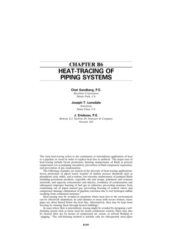
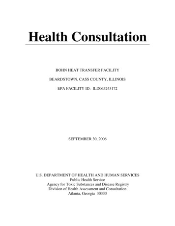
IntroductionCable TestingA complete electric heat tracing system willtypically include the following components:After a heat tracing circuit has been installed andfabricated and before the thermal insulation isinstalled, the heating cable should be tested toensure electrical resistance integrity. The cableshould be tested with at least a 500 Vdc megohmmeter (megger) between the heating cable buswires and the heating cable metallic braid. It isrecommended that the test voltage for polymerinsulated heating cables be 2500 Vdc or 1000 Vdcfor MI cable.1. Electric heattracing cable1(self-regulating,power-limiting,parallel constantwatt or seriesresistance).5642. Powerconnectionkit.After properly terminating the cable, connect thepositive lead of the megger to the bus wires andthe negative lead to the metallic braid as shown.The minimum acceptable level for the meggerreading for any polymer-insulated heat tracingcable is 20 megohms. This test should be repeated after the thermal insulation and weatherbarrier have been installed.83. Control thermostat2.74. In-line/T-splice kit(permits two or threecables to be spliced together).15. Cable end termination.6. Attachment tape (use on 12"intervals or as required by codeor specification).7. “Electric Heat Tracing”label (peel-and-stick labelattaches to insulationvapor barrier on 10'intervals or as requiredby code or specification).3Connect the positive lead of the megger to the cablebus wires and the negative lead to the metallic braid.28. Thermal insulation3 andvapor barrier (by others).The absence of any of these items cancause a system to malfunction or represent asafety hazard.Notes . . .1. Ground-fault maintenance equipment protection is required for allheat tracing circuits.2. Thermostatic control is recommended for all freeze protection andtemperature maintenance heat tracing applications.3. All heat-traced lines must be thermally insulated.1
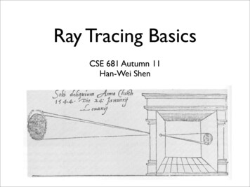
Thermal InsulationFinal InspectionThe value of properly installed and well-maintainedthermal insulation cannot be overemphasized.Without the insulation, the heat loss is generallytoo high to be offset by a conventional heat tracingsystem.The heating circuit can now be tested for properoperation. This includes measuring and recordingthe connected voltage, steady-state current draw,length and type of cable, ambient temperature andtemperature of the pipe. (See the InspectionReport Form on page 3.)Before the thermal insulation is installed on a heattraced pipe, the tracing circuit should be tested fordielectric insulation resistance. This will ensure thatthe cable has not been damaged while exposed onthe uninsulated pipe.The complete system (especially the thermalinsulation) should now be visually inspected.Additional insulation should be applied snuglyaround pipe shoes or other heat sinks and sealedfrom the weather. Expansion joints on hightemperature lines should be examined carefully.There may be exposed insulation where sections fittogether or around flanges, valves, pipe hangers orconnection kits; these locations should be sealedto prevent ingress of moisture.In addition to piping and in-line equipment such aspumps and valves, all heat sinks must be properlyinsulated. This includes pipe shoes, hangers,flanges and, in many cases, valve bonnets.There are many different pipe insulation materials,each of which has advantages in particular applications. Regardless of the type or thickness ofinsulation used, a protective barrier should beinstalled. This protects the insulation from moistureintrusion and physical damage and helps ensurethe proper performance of the heat tracing system.“Electric Heat Tracing” caution labels should beapplied to the outer surface of the weather barrierat regular intervals of 10 feet (or as required bycode or specification). The location of splices andend terminations should also be marked with spliceand end termination caution labels.Notes . . .Maintenance When rigid (noncompressible) materials are used, the inside diameterof the insulation is usually oversized to accommodate the heating cableon the pipe.Once the heat tracing system has been installed,an ongoing preventive maintenance programshould be implemented using qualified personnel.Support documentation providing general information and an operating history of the specific circuits in the system should be maintained. Insulating materials are very susceptible to water absorption, whichdramatically increases the heat loss and should be replaced if the materials get wet.The results of the operational testing describedabove form the testing “base line” or normal range.Subsequent measurements should be recordedperiodically and compared to this base-line data tohelp identify potential malfunctions.2
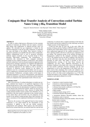
Inspection Report Form for Electric Heat Tracing (Typical)LocationSystemReference Drawing(s)CI RCUIT I NFORMATIONCircuit LengthDesign VoltageGround-Fault Protection (type)Ground-Fault Trip SettingHeater Cat. No.Power ConnectionTee ConnectionSplice ConnectionHeater ControllerBkr. Panel No.Bkr. Pole(s) No.VISUALPanel NumberCircuit #DateInitialThermal InsulationDamaged Insulation/LaggingWater Seal GoodInsulation/Lagging MissingPresence of MoistureHeating System ComponentsEnclosures, Boxes SealedPresence of MoistureSign of CorrosionHeater Lead DiscolorationHeating and/or High Limit ControllerOperating ProperlyController SetpointELECTRICALDielectric Insulation Resistance Testing (bypass controller if applicable) Refer to I EEE 515-1997, Section 7.9Test VoltageMegger ValueHeater Supply VoltageValue at Power SourceValue at Field ConnectionHeater Circuit Current ReadingPipe TemperatureAmps Reading at 2-5 min.Amps Reading After 15 min.Ground-Fault CurrentComments and ActionsPerformed byCompanyDateApproved byCompanyDateUse this form as an original to make copies3
TroubleshootingThe following information is intended to assist in troubleshooting electric heat tracing systems. Theprimary objective is to provide an enhanced understanding of the elements of a successful heat tracinginstallation. Of these elements, one of the most important is the thermal insulation.Before calling the heat tracing vendor, make a visual inspection of the installation; perhaps the thermalinsulation is wet, damaged or missing. Also consider the possibility that repairs or maintenance of in-lineor nearby equipment may have resulted in damage to the heat tracing equipment. These are commoncauses of tracing problems which are often overlooked. Other possible causes are listed below with theirsymptoms and remedies.If an electric heat tracing circuit is suspected to be damaged, a dielectric insulation resistance (megger)test should be performed using a 2500 Vdc megohmmeter for polymer-insulated heating cables or 1000Vdc for MI cable. Periodic testing with accurate records will establish a “normal” range of operation (referto the Inspection Report Form on page 3). Dielectric insulation resistance readings which deviate fromthe normal range can quickly reveal a damaged circuit.SymptomPossible CauseRemedyI. No heat/no currentA. Loss of power (voltage)A. Restore power to tracing circuit(check circuit breaker and electricalconnections). Poorly made terminations can cause EPD-type breakersto trip unexpectedlyB. Adjust setpointC. May require manual reset to reenable heat tracing circuitD. Repair or replace circuit1E. Repair sensor or controller2B. Controller setpoint too lowC. High temperature limit switchactivatedD. “Open” series heating circuitE. Controller failureII. Low system temperatureA. Controller setpoint too lowB. Temperature sensor located tooclose to heating cable or other heatsource; may be accompanied byexcessive cycling of control relays/contactsC. Insulation material and/or thicknessdifferent than designedD. Ambient temperature lower thandesignedE. Low voltage (check at powerconnection point)4A. Adjust setpointB. Relocate sensorC. Replace insulation; increaseinsulation thickness (if dry);consider increasing voltage forhigher cable output3D. Install higher output heating cable;increase insulation thickness; raisevoltage3E. Adjust voltage to meet designrequirements3
SymptomPossible CauseRemedyIII. Low temperature insectionsA. Wet, damaged or missing insulationA. Repair or replace insulation andjacketB. Repair or replace; splice kits areavailable from cable manufacturerC. Insulate heat sinks or increaseamount of tracing on heat sinksD. Consider dividing heating circuitinto separate, independentlycontrolled segmentsB. Parallel heating cable; open elementor damaged matrixC. Heat sinks (valves, pumps, pipesupports, etc.)D. Significant changes in elevationalong length of the heat-traced pipeIV. High system temperatureA. Controller “on” continuouslyB. Controller failed with contactsclosedC. Sensor located on uninsulated pipeor too close to heat sinkD. Backup heating circuit controller“on” continuouslyV. Excessive cyclingVI. Temperature variationsfrom setpoint alongpipelineA. Adjust setpoint or replace sensor2B. Replace sensor or controller2C. Relocate sensor to an area representative of conditions along entirepipe lengthD. Adjust setpoint or replace backupcontrollerA. Temperature sensor located tooclose to heating cable or other heatsource; may be accompanied bylow system temperatureB. Ambient temperature near controller setpointC. Connected voltage too highD. Heating cable output too high(overdesign)E. Controller differential too narrowA. Relocate sensorA. Unanticipated flow patterns orprocess operating temperaturesA. Redistribute heating circuits to accommodate existing flow patterns;confirm process conditionsB. Check method of cable installation,especially at heat sinksC. Compare calculated watts/foot[(volts x amps) length] for themeasured pipe temperature withdesigned cable output for the sametemperature; regional damage toparallel cable can cause partialfailureB. Inconsistent cable installation alongpipelineC. Inconsistent cable performanceB. Temporarily alter controller setpointC. Lower voltageD. Install lower output heating cable orlower voltageE. Widen differential or replace controller to avoid premature contactfailureNotes . . .1. Flexible, plastic-jacketed heating cables may be field-spliced; MI cables usually require replacement.2. Mechanical thermostat sensors cannot be repaired or replaced; RTD or thermocouple sensors can be replaced. Some controllers have replaceablecontacts/relays or may require a manual reset if a “trip-off” condition on the heating circuit was detected.3. The operation of most electric heat tracing cables is dramatically affected by changes in the supply voltage. Before making any changes, consult thecable manufacturer with information on the alternate voltages available. Otherwise, cable failure and/or an electrical safety hazard may result insome situations.5
Printed in U.S.A. Thermon Manufacturing Co.Form TEP0066-0800PN 20745THERMON . . . The Heat Tracing Specialists 100 Thermon Dr.PO Box 609San Marcos, TX 78667-0609Phone: 512-396-5801Facsimile: 512-396-3627800-820-HEATwww.thermon.comIn Canada call 800-563-8461
meter (megger) between the heating cable bus wires and the heating cable metallic braid. It is recommended that the test voltage for polymer-insulated heating cables be 2500 Vdc or 1000 Vdc for MI cable. After properly terminating the cable, connect the positive lead of the megger to the bus wires and the negative lead to the metallic braid as shown. The minimum acceptable level for the megger .