Transcription
ELECTRICAL INSULATION TESTINGOF HV EQUIPMENTUP TO 33kV1.SUB-02-613Issue No. 2SCOPEThis document details PowerSystems requirements for electrical testing of HV Equipment up to andincluding 33kV.2.ISSUE RECORDThis is a Reference document. The current version of Controlled and Reference documents is heldon the Energy Networks Intranet Document Library.It is your responsibility to ensure you work to the current version.Issue DateNovember 02September 20133.Issue No.12AuthorAlastair GrahamJohn RussellAmendment DetailsInitial IssueDocument ReviewedISSUE AUTHORITYAuthorJohn RussellLead EngineerOwnerDavid NeilsonSubstation ManagerIssue AuthorityJane WilkieHead of Asset ManagementDate: .10/09/2013.4.REVIEWThis is a Reference document which has a 10 year retention period after which a reminder will beissued to review and extend retention or archive.5.DISTRIBUTIONThis document is not part of a Manual but it is published to the Energy Networks Internet site. SP Power Systems LimitedPage 1 of 19
ELECTRICAL INSULATION TESTINGOF HV EQUIPMENTUP TO 33kV6.SUB-02-613Issue No. 2CONTENTS1. SCOPE . 12. ISSUE RECORD . 13. ISSUE AUTHORITY . 14. REVIEW . 15. DISTRIBUTION. 16. CONTENTS . 27. REFERENCES . 38. RELATED DOCUMENTS . 49. POLICY . 59.1Electrical Tests Required Prior to Connection to the System . 59.2Electrical Tests Required Prior to Energisation . 810. GENERAL REQUIREMENTS . 910.1Safety Precautions for Pressure Testing . 910.2Special Precautions with Vacuum Switchgear . 910.3Procedure in Cases Where Pressure Testing is Not Possible . 911. TESTING METHODS AND TEST VOLTAGES . 1011.1Switchgear . 1011.2Cables . 1111.2.111.2.211.311.3.111.3.211.411.4.111.4.2Test Voltages . 11Cable Oversheath Tests for 33kV xlpe Cables . 13Power Transformers . 14Pole Mounted and Secondary Ground Mounted Transformers . 14Primary Transformers . 15Voltage Transformers . 16Un Earthed Primary Winding. 16Earthed Primary Winding . 1712. TESTING OF COMBINED EQUIPMENT . 1813. APPENDIX 1: DERIVATION OF TEST VOLTAGES . 1914. APPENDIX 2: FLOW CHART . 19 SP Power Systems LimitedPage 2 of 19
ELECTRICAL INSULATION TESTINGOF HV EQUIPMENTUP TO 33kV7.SUB-02-613Issue No. 2REFERENCESFor the purpose of this Specification the following definitions shall apply:Company:Refers to SP Distribution plc, SP Transmission plc and SP Manwebplc.PowerSystems:SP PowerSystems Ltd, operator of network assets on behalf of theCompany.SP Transmission plcThe Transmission Licence Holder for the transmission service areaformally known as ScottishPower.SP Distribution plcThe Distribution Licence Holder for the distribution service areaformally known as ScottishPowerSP Distribution plcThe Distribution Licence Holder for the distribution service areaformally known as ScottishPowerAC Pressure Test:AC Power Frequency overvoltage test to ascertain suitability of plantfor energisation.DC Pressure Test:DC overvoltage test to ascertain suitability of plant for energisation.Equipment:Switchgear, transformers, cables, overhead lines, surge arresters,voltage transformers, current transformers, unit substations.Energisation:The application of Voltage to an item(s) of Equipment from thesystem.High Voltage:An AC voltage exceeding 1000 volts measured between the phaseconductors.Insulation Resistance Test:Impedance test to ascertain condition of insulation prior toenergisation.Approved:Equipment which is Approved in accordance with PowerSystemsdocuments for use or installation on the Company network.New:Approved Equipment which has not previously been connected to thesystem and which has been routine tested in a Manufacturing Facilitywith a Quality Management System in accordance with the relevantstandard prior to delivery.Combined Equipment:Equipment connected with other EquipmentPreviously In Service:Equipment which, has previously been connected to the system andis deemed suitable for re-use in accordance with PowerSystemsdocument, ASSET-01-010, PowerSystems Plant Re-Use policy, andhas been electrically tested in accordance with the requirementsdetailed in this document.Site Assembled ConnectionsConnections made/modified on site or insulation which has in someway been affected subsequent to factory testing or testingundertaken for Previously In Service Equipment. This does notinclude cable connections. SP Power Systems LimitedPage 3 of 19
ELECTRICAL INSULATION TESTINGOF HV EQUIPMENTUP TO 33kV8.SUB-02-613Issue No. 2RELATED DOCUMENTSIt is important that users of the documents listed below ensure that they are in possession of the latestissues of the documents together with any amendments.Statutory LegislationESR 88Electricity Supply Regulations, 1988 (as amended)PowerSystemsthScottishPower Safety Rules, Electrical and Mechanical 4 Edition.OHL-04-005,3.4.1)Distribution Construction Manual - Overhead Line, Construction (DCMPractisesASSET-01-010PowerSystems Plant Re-Use policy SP Power Systems LimitedPage 4 of 19
ELECTRICAL INSULATION TESTINGOF HV EQUIPMENTUP TO 33kV9.SUB-02-613Issue No. 2POLICYPrevious Testing Policy’s were based on the 1937 Electricity Supply Regulations which obligedDistribution Network Operator’s, to undertake Electrical Tests prior to connection of Equipment to thesystem. The Electricity Supply Regulations 1988, as amended, do not require Distribution NetworkOperator’s to Pressure Test Equipment prior to installation onto the system. However ESR88,regulation 17 states “All supplier’s works shall be sufficient for, and the circumstances in, which theyare used and so constructed, installed, protected (both electrically and mechanically), used, andmaintained as to prevent danger or interruption of supply so far as is reasonably practicable”.The PowerSystems policy for electrical testing of Company Equipment, outlined below, has beendeveloped giving due consideration to the risks and the practical benefits. It is important not tooverstress Equipment by inappropriate repetition of type or routine tests under inadequate siteconditions. However, it is necessary to confirm that no damage has occurred during transportationand erection of the Equipment. The assessment undertaken by PowerSystems has shown thatrepeating manufacturers routine tests on New Equipment does not significantly detect manufacturingdefects, but does potentially increase the risk to PowerSystems personnel on site. Thereforerepeating manufacturers routine tests shall not be undertaken. For Previously In Service Equipment,appropriate tests shall be undertaken prior to installation at site in accordance with this document.9.1Electrical Tests Required Prior to Connection to the SystemWhen New Equipment is to be connected to the system for the first time or where Previously InService Equipment which has been refurbished and is to be re-used, then prior to connectionto the system, the Equipment shall be electrically tested in accordance with Tables 1 – 6,outlined.Where Equipment is being transferred from an energised in service position, to be immediatelyconnected and energised to the system at another site, without refurbishment work having takenplace, then there is no requirement to undertake prior to site AC pressure tests as detailed in tables 1–6. Where required by Tables 1-6, AC pressure testing at site shall still apply. SP Power Systems LimitedPage 5 of 19
ELECTRICAL INSULATION TESTINGOF HV EQUIPMENTUP TO 33kVTable 1Switchgear:11kV, RMU’s, switches andextensible secondaryswitchgearNew:No AC pressure testPrimary and 33kV extensibleswitchgear.Outdoor 33kV circuit breakers.AC pressure test SiteAssembled Connections at site,in accordance with tests 1-3,section 10.1 Table 8 for NewEquipment. (1)Air-break switch disconnectorsand Pole mounted expulsionfusesPMAR’s and pole mountedenclosed metal switchesNo AC pressure test33kV RMU’sNote (1)Previously In Service:AC pressure test prior to site, inaccordance with tests 1-4,section 10.1 Table 8 forPreviously In ServiceEquipment.AC pressure test prior to site, inaccordance with tests 1-4,section 10.1 Table 8 forPreviously In ServiceEquipment.AC pressure test SiteAssembled Connections at site,in accordance with tests 1-3,section 10.1 Table 8 forPreviously In ServiceEquipment.No AC pressure testAC pressure test prior to site, inaccordance with tests 1-4,section 10.1 Table 8 forPreviously In ServiceEquipment.AC pressure test SiteAC pressure test prior to site, inAssembled Connections at site, accordance with tests 1-4,in accordance with tests 1-3,section 10.1 Table 8 forsection 10.1 Table 8 for NewPreviously In ServiceEquipment.Equipment.AC pressure test SiteAssembled Connections at site,in accordance with tests 1-3,section 10.1 Table 8 forPreviously In ServiceEquipment.Where a New panel is being added to a Previously In Service, in situ extensibleswitchboard, the busbars shall be tested in accordance with the Previously In ServiceTest Values, Table 8. SP Power Systems LimitedNo AC pressure testSUB-02-613Issue No. 2Page 6 of 19
ELECTRICAL INSULATION TESTINGOF HV EQUIPMENTUP TO 33kVSUB-02-613Issue No. 2Table 2CablesCable section with or without joint/termination (2)Note(2):NewNo pressure test.5kV insulation resistance test on cableoversheath for 33kV xlpe cables, in accordancewith section 10.2.2.It may be prudent in certain circumstances to pressure test the cable section prior toconnection to the system where it is considered appropriate to do so.Table 3Transformers and VoltageRegulators:Pole MountedNewPreviously In ServiceNo AC pressure test.Insulation Resistance Test(megger) on site, in accordancewith section 10.3.1, installed onpole.No AC pressure test.No AC pressure test.Insulation Resistance Test(megger) on site, in accordancewith section 10.3.2.No AC pressure test.Insulation Resistance Test(megger) on site, in accordancewith section 10.3.1, installed onpoleNo AC pressure test.Insulation Resistance Test(megger) on site, in accordancewith section 10.3.1.No AC pressure test.Insulation Resistance Test(megger) on site, in accordancewith section 10.3.2.Voltage Transformers andMetering UnitsUn-Earthed Primary WindingNewPreviously In Service500V Insulation ResistanceTest (megger) the secondary(LV) winding at site, inaccordance with section 10.4.1,table 7.Earthed Primary Winding500V Insulation ResistanceTest (megger) the secondary(LV) winding at site, inaccordance with section 10.4.2,table 9.AC Pressure Test prior to site,in accordance with section10.4.1, table 8.500V Insulation ResistanceTest (megger) the secondary(LV) winding at site, inaccordance with section 10.4.1,table 7.500V Insulation ResistanceTest (megger) the secondary(LV) winding at site, inaccordance with section 10.4.2,table 9.Ground Mounted SecondaryPrimaryTable 4Table 5Surge ArrestersTable 6Unit Substations & PadMountsUnit Substation SP Power Systems LimitedNewNo pressure test.Previously In Service5kV Insulation Resistance Test(megger) on site.NewPreviously In ServiceNo pressure test.AC pressure test prior to site, inaccordance with section 10.1Page 7 of 19
ELECTRICAL INSULATION TESTINGOF HV EQUIPMENTUP TO 33kV9.2SUB-02-613Issue No. 2Electrical Tests Required Prior to EnergisationPrior to Combined Equipment being energised at system voltage, electrical tests shall beperformed in accordance with Table 7.Table 7Combined EquipmentCable Switchgear excluding Transformer (3), (4),(5)Cable Switchgear including Transformer (3), (4), (5)Cable TransformerCable Cable11kV fault repairs and smalldeviations, typically less than30mAll other 11kV cable –cableinstallationsPhase – Phase and Phase – Earth, DCpressure test combined installation inaccordance with section 11.Phase- Earth, DC pressure test combinedinstallation in accordance with section 11.Phase- Earth, DC pressure test combinedinstallation in accordance with section 11.5kV Insulation Resistance Test (megger).Phase – Phase and Phase – Earth (whereappropriate), DC pressure test combinedinstallation in accordance with section 11.33kV cable – cablePhase – Earth, DC pressure test combinedinstallationsinstallation in accordance with section 11.Overhead Line Pole Mounted Equipment5kV Insulation Resistance Test (megger),installed on pole.Visual Inspection in accordance withPowerSystems document OHL-04-005.Notes (3)Surge Arresters may be left connected during DC Pressure Testing(4)Precautions shall be taken to disconnect VT’s prior to DC Pressure Testing.(5)33kV outdoor circuit breaker no additional DC test required. SP Power Systems LimitedPage 8 of 19
ELECTRICAL INSULATION TESTINGOF HV EQUIPMENTUP TO 33kV10.SUB-02-613Issue No. 2GENERAL REQUIREMENTSElectrical tests shall be carried out by suitably Authorised or trained Persons using PowerSystemsApproved Equipment. The testing shall be conducted in accordance with the requirements of thecurrent ScottishPower Safety Rules, Electrical & Mechanical, where applicable.The pressure test voltage shall be increased gradually to the specified value and maintained for thespecified time.10.1Safety Precautions for Pressure TestingSpecial precautions shall apply for high voltage testing to ensure safety:In locations permanently set aside for pressure testing, the control point shall be such that theoperator has full view of the apparatus under test to ensure that no one is in the danger zone.Security arrangements in the danger zone shall incorporate a reliable system of indications andalso where applicable interlocks that de-energise the zone if anyone attempts to enter it.Where testing is to be done on site, then this shall be done in accordance with the Scottish PowerSafety Rules, PSSI 9.For reasons of both safety and accuracy, it is essential that the Equipment under test be earthedboth before and after the application of the test potential.10.2Special Precautions with Vacuum SwitchgearVacuum switchgear, may generate x-rays when the open contact gap is stressed at high voltage,however under normal system voltage and pressure test values detailed within this document, thereare no harmful emissions. As an additional safeguard to personnel, the Equipment must be testedwith the vacuum interrupters contained in the manufacturers’ normal housing and all personnel bepositioned not less than 2 metres away from the unit under test.10.3Procedure in Cases Where Pressure Testing is Not PossibleIn exceptional circumstances where on-site testing is not possible but is required by thisdocument, then prior to any Equipment being Energised, written authority shall be obtainedfrom the Customer Operations Manager or his nominated representative.In some cases where this document requires prior to site tests, it may be permissible toundertake these tests at site. This shall be at the discretion of the Customer OperationsManager or his nominated representative. SP Power Systems LimitedPage 9 of 19
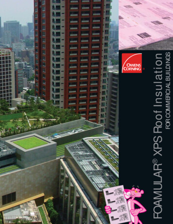
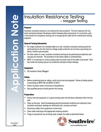
ELECTRICAL INSULATION TESTINGOF HV EQUIPMENTUP TO 33kV11.SUB-02-613Issue No. 2TESTING METHODS AND TEST VOLTAGESPowerSystems testing policy requires a combination of both AC and DC Pressure Testing andInsulation Resistance Testing, as detailed within section 8. Irrespective of whether AC or DC testing iscarried out the insulation will retain a high voltage charge upon completion of the test. For safetyreasons this shall be safely discharged through an impedance to earth.11.1SwitchgearWhere required by section 8.1, Pressure test voltages shall be AC at power frequency in accordancewith Table 1 and the appropriate values detailed in Table 8. The test connections shall be as shownin Figure 1. In tests 1,2 and 3 the tests voltage shall be carried out on the conductors of all sections ofthe switchgear by closing the switch device in order to test the complete assembly. Wherecircumstances preclude this, the test shall be applied to each discrete portion, as necessary.Test1Test 2Test 3Test 4Open positionTestsetTestsetTestsetTestsetFigure 1. Test Connections for Pressure Testing SwitchgearVoltage transformers shall be isolated during the pressure testing of the switchgear by beingwithdrawn or on non withdrawable units, by removing the HV connection. Current transformerssecondaries shall not normally be short circuited nor shall relays, instruments and other auxiliaryapparatus be disconnected. SP Power Systems LimitedPage 10 of 19
ELECTRICAL INSULATION TESTINGOF HV EQUIPMENTUP TO 33kVSUB-02-613Issue No. 2Table 8. Test Voltages for SwitchgearRatedVoltage (kV)AC test voltage (kV rms)New EquipmentPreviously 6.0Test Duration - 1 minuteThe above test values are for discrete switchgear apparatus (ie before being connected to thesystem). The values shall not be employed for switchgear that forms part of the system. Afterthe switchgear is connected to the system the combined Equipment shall be DC pressuretested in accordance with section 8.2 and test values detailed in section 11, Table 10.11.2CablesIt is not normally required to pressure test cables prior to connection to the system, however it may beprudent in certain circumstances to pressure test the New cable section prior to connection to thesystem where it is considered appropriate to do so.Where deemed necessary by Table 2, DC test voltages shall be used for pressure testing cables. Therespective test voltages and test connections are indicated in the following sections.11.2.1 Test VoltagesWhere deemed necessary by Table 2, the test voltages for complete cable circuits shall be inaccordance with the values given in Table 9. The test connections are shown in Figures 2, 3 and 4The current observed during a DC pressure test will initially include the charging current. After fullvoltage is reached the charging current will decay and the remaining leakage current is used toindicate the condition of the cable. The leakage current of a healthy cable should be less than 0.2mAalthough it may be greater depending on the length of cable and termination arrangement. SP Power Systems LimitedPage 11 of 19
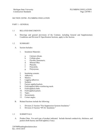
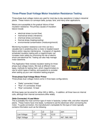
ELECTRICAL INSULATION TESTINGOF HV EQUIPMENTUP TO 33kVSUB-02-613Issue No. 2Table 9. Test Voltages cablesVoltage (kV)3.36.6112233DC test voltage (kV)New cables OnlyPhase - Phase Phase - Earth531066[6]171010[6]1020203030Test duration – 5 minutesCable TypeBelted PaperBelted PaperScreened XLPEBelted paperScreened PaperScreened XLPEScreened PaperScreened XLPEScreened PaperScreened XLPENote:[6] Not applicable - phase to phase tests are not carried out for screened cablesWhere the circuit to be tested includes both belted and screened cable types, the test connectionsappropriate to screened cables shall be used and only the appropriate phase to earth tests shall becarried out.The cable under test must be discharged to earth after each pressure test and the conductors must allbe connected to earth whilst the test lead connections are being modified.Test 1Phase - Phase(Belted papercables only)DCTest 2Phase - Phase(Belted papercables only)DCTest 3All Phases – Sheath(All paper cables)DCFigure 2. Test Connections for Pressure Testing Complete Paper Insulated Cable Circuits SP Power Systems LimitedPage 12 of 19
ELECTRICAL INSULATION TESTINGOF HV EQUIPMENTUP TO 33kVTest 1Phase 1 – SheathDCTest 2Phase 2 – SheathDCSUB-02-613Issue No. 2Test 3Phase 3 – SheathDCFigure 3. Test Connections for Pressure Testing three core Polymeric Cable CircuitsDCFigure 4. Test connections for Pressure testing single core polymeric cables11.2.2 Cable Oversheath Tests for 33kV xlpe CablesThe oversheaths of 33kV xlpe insulated cables shall be tested and proved to be intact after laying andbackfilling but before jointing/connection.A 5kV insulation resistance test shall be applied for 1 minute between the copper screen wiresand an earth electrode. Cables for use in ducted installations shall have a conductive outerlayer and the insulation resistance test shall be applied between this layer and the screenwires. SP Power Systems LimitedPage 13 of 19
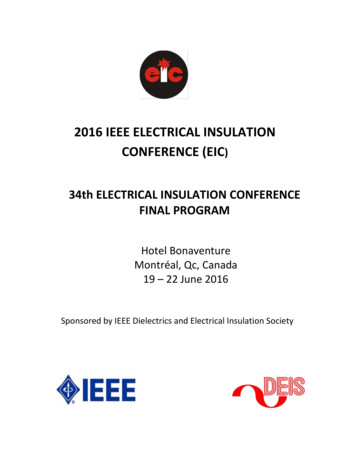
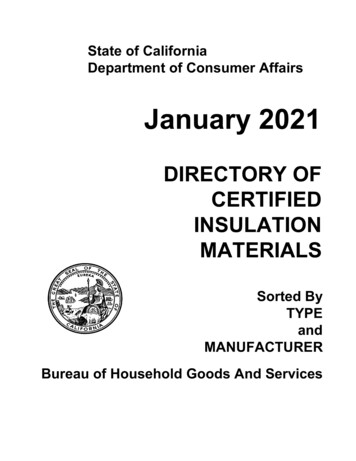
ELECTRICAL INSULATION TESTINGOF HV EQUIPMENTUP TO 33kV11.3SUB-02-613Issue No. 2Power TransformersWhere required by section 8, transformers shall be Insulation Resistance tested. A distinction is madebetween primary and secondary transformer types with the respective test connections indicated inthe following sections.11.3.1 Pole Mounted and Secondary Ground Mounted TransformersWhere required by section 8.1, Table 3, Pole mounted and secondary ground mounted transformersshall be tested after erection and prior to energisation.The test shall comprise two parts, 1) the HV winding tested to the LV and earth, and 2) the LV windingtested to HV and earth.Test 1) shall be made by application of a voltage of 5kV to the HV winding applied for 1 minute.Test 2) shall be made by the application of a voltage of 1kV applied to the LV winding for 1 minute.The test voltage may be derived from a suitably Approved constant voltage insulation test set.The transformer shall be considered suitable for connection to the system if the insulation of bothwindings is greater than 200 MΩ. (This value may be affected by moisture on exterior bushings)The test connections to be used are detailed in Figure 5.Test 1 - HV Winding TestTest 2 - LV Winding Test1kV5kVFigure 5. Test Connections for Insulation Resistance Testing Pole Mounted and SecondaryGround Mounted Power Transformers SP Power Systems LimitedPage 14 of 19
ELECTRICAL INSULATION TESTINGOF HV EQUIPMENTUP TO 33kVSUB-02-613Issue No. 211.3.2 Primary TransformersIn addition to the pre-commissioning checks required for new primary transformers, each transformershall be subjected to an on site insulation resistance test prior to commissioning.The test shall comprise two parts, 1) the HV winding tested to the LV and earth, and 2) the LV windingtested to HV and earth.The tests shall be made by application of a voltage of 5kV to the winding under test, applied for 1minute. The test voltage may be derived from a suitably Approved constant voltage insulation testset.The transformer shall be considered suitable for connection to the system if the insulation of bothwindings is greater than 200 MΩ. (This value may be affected by moisture on exterior bushings)The test connections to be used are detailed in Figure 6.Test 1 - HV Winding TestTest 2 - LV Winding Test5kV5kVFigure 6. Test Connections for Insulation Resistance Testing of Primary Transformers SP Power Systems LimitedPage 15 of 19
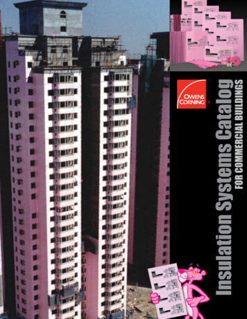
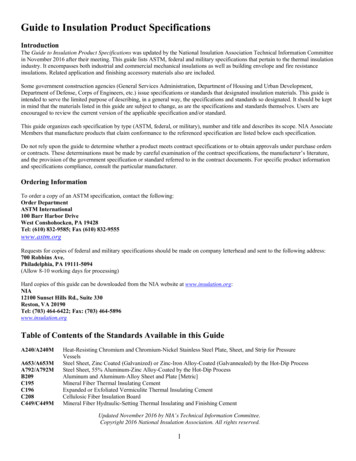
ELECTRICAL INSULATION TESTINGOF HV EQUIPMENTUP TO 33kV11.4SUB-02-613Issue No. 2Voltage TransformersVoltage transformers shall be tested in accordance with section 8.1 table 4, prior toenergisation.11.4.1 Un Earthed Primary Winding500VV500VVFig 7. Insulation Resistance LV Winding TestWhere the yellow phase is earthed, the earth link shall be removed prior to testing. The test voltage of500V shall be applied for 1 minute between earth and all terminals of the secondary windingconnected together. All other terminals shall be earthed. On completion of the test the yellowphase earth link shall be replaced, where appropriate.ACACFig 8. AC Pressure TestAC Pressure Test, in accordance with section 10.1, Table 8 for Previously In Serviceswitchgear. The test voltage shall be applied for 1 minute between earth and all the terminalsof the primary winding. The test connections shown should not be used for VT’s with earthedprimary windings, as the test voltage may result in breakdown of the star point insulation. SP Power Systems LimitedPage 16 of 19
ELECTRICAL INSULATION TESTINGOF HV EQUIPMENTUP TO 33kVSUB-02-613Issue No. 211.4.2 Earthed Primary Winding500VVFig 9. Insulation Resistance LV Winding TestThe test voltage of 500V shall be applied for 1 minute between earth and all terminals of thesecondary winding connected together. All other terminals shall be earthed. The primary earthshould not be removed for testing. SP Power Systems LimitedPage 17 of 19
ELECTRICAL INSULATION TESTINGOF HV EQUIPMENTUP TO 33kV12.SUB-02-613Issue No. 2TESTING OF COMBINED EQUIPMENTElectrical tests on Combined Equipment where required by section 8.2, shall be undertakenprior to energisation at the test voltages detailed in table 10.Table 10. Test Voltages for Combined EquipmentRatedVoltage(kV)DC test voltage (kV)Phase - PhasePhase - 30.0Test Duration - 5 minutesThe design specification for all existing switching devices are such that there is a substantial marginof safety across the isolating gap when it is stressed on either side by simultaneous application ofsystem and test voltages for combined plant given in Table 10. SP Power Systems LimitedPage 18 of 19
ELECTRICAL INSULATION TESTINGOF HV EQUIPMENTUP TO 33kV13.SUB-02-613Issue No. 2APPENDIX 1: DERIVATION OF TEST VOLTAGESThis appendix has been included to detail how the values for AC and DC Pressure Test voltages werederived.RatedSystemVoltage of Voltage:Equipment Phase PhaseSystemVoltagePhase Earth(7)12000120003600036000New ACPressureTest, IEC298ReducedValue 300DCDCPressurePressureTest Phase - Test Phase EarthPhase(Combined) 410267171123422451336Notes:(7)(8)(9)(10)(11)14.For 6.6kV the rated voltage of New Equipment is 12kV, For 22kV the rated voltage of NewEquipment is 36kV.New AC Pressure Test, IEC 694: For switchgear, Appendix DD of IEC 298. This is 80% ofvalues detailed in table 1a of IEC694.Reduced Value AC Pressure Test, for Previously In Service Switchgear. System voltage * 1.1.DC Pressure Test, Phase – Earth. System voltage * sqrt(2) * 1.1) / sqrt (3)DC Pressure Test, Phase – Phase. System voltage * sqrt(2)APPENDIX 2: FLOW CHARTSee Document SUB-02-613 (Appendix 2), published separately. SP Power Systems LimitedPage 19 of 19
Test (megger) the secondary (LV) winding at site, in accordance with section 10.4.2, table 9. 500V Insulation Resistance Test (megger) the secondary (LV) winding at site, in accordance with section 10.4.2, table 9. Table 5 Surge Arresters New Previously In Service No pressure test. 5kV Insulation Resistance Test (megger) on site. Table 6