Transcription
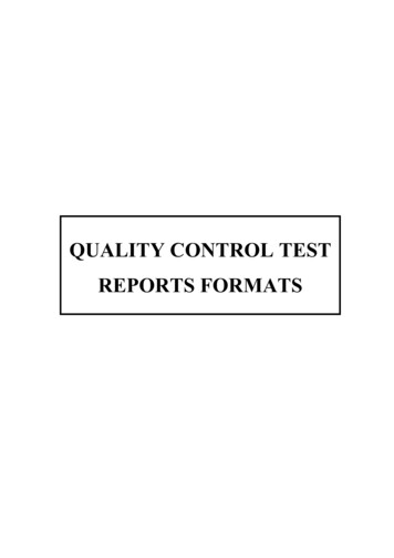
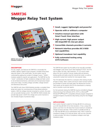
SMRT36Megger Relay Test SystemSMRT36Megger Relay Test SystemSMRT36 with optionalTransducer hardwareDescriptionFor size, weight, and features the SMRT36 is conceivably thesmallest, lightest, highest output powered, complete three phaserelay test system in the world today. The test system may becustomized by adding the number of Voltage-Current, “VIGEN”,modules needed for specific test applications. The SMRT36 has the“smart” combination of high compliance voltage and high currentto test all electromechanical, solid-state and microprocessor-basedovercurrent relays, including voltage controlled, voltage restraintand directional overcurrent.The SMRT36 with three VIGEN Modules provides a complete threephase test system for commissioning of three phase protectionsystems. With the voltage channels converted to currents, the sameunit can provide 6-phase current. The SMRT36 VIGEN modules alsoprovide high power in BOTH the voltage and current channels totest virtually all types of protective relays.nSmall, rugged, lightweight and powerfulnOperate with or without a computernIntuitive manual operation withSmart Touch View InterfacenHigh current, high power output(60 Amps/300 VA rms) per phasenConvertible channels provides 6 currentsnNetwork interface provides IEC 61850test capabilitiesnOptional transducer test capabilitynFully automated testing usingAVTS SoftwareThe SMRT36 test system has the ability to be manually controlledwith Megger’s new Smart Touch View Interface (STVI). The STVI,with its large, full color, high resolution, TFT LCD touch screenallows the user to perform manual, steady-state and dynamictesting quickly and easily using the manual test screen, as well asusing built-in preset test routines for most popular relays.The STVI eliminates the need for a computer when testing virtuallyall types of relays. Menu screens and touch screen function buttonsare provided to quickly and easily select the desired test function.Tests results can be saved to the STVI for download to a memorystick to transfer or print test reports.For full automatic testing the SMRT36 may be controlled by MeggerAdvanced Visual Test Software (AVTS). AVTS is a Microsoft Windows XP /Vista /7 compatible software program designed tomanage all aspects of protective relay testing using the new MeggerSMRT.ApplicationsEach current channel is rated for 30 Amps @ 200 VA continuous,up to 60 Amps @ 300 VA for short durations. It has a unique flatpower curve from 4 to 30 Amps that insures maximum compliancevoltage to load at all times. Three currents in parallel provide upto 180 Amps @ 900 VA for instantaneous tests. With a maximumcompliance voltage of 50 Volts per phase, with just two channelsin series provides 100 Volts of compliance voltage to test highimpedance relays.SMRT36 with STVI
SMRT36Megger Relay Test SystemBuilt-in Transducer Testing Capability – The SMRT36Pincorporates high accuracy amplifiers, an optional transducer DCinput and test algorithms to test transducers easily and effectively.Each voltage channel can provide variable outputs of 0- 30/150/300 Volts at 150 VA of output power, and has a unique flat powercurve from 30 to 150 Volts insuring maximum output power to theload at all times. With the voltage channel converted to current, athree channel unit can provide 6 currents for testing three phasecurrent differential relays, including harmonic restraint transformerdifferential relays.Digital binary inputs and outputs – The programmable binaryinputs, and programmable outputs provide timing and logicoperations in real-time with the output voltage and currents. BinaryInputs can be programmed, using Boolean logic, for more complexpower system simulations. This provides a low cost, closed loop,power system simulator.Using the Ethernet ports, the SMRT36 is literally a “plug-andplay” unit, where voltage and current outputs can be seamlesslysynchronized with other SMRT units outputs for testing morecomplex test applications such as back-to-back tests, or 9 up to12phase current test applications.Circuit breaker simulator – Binary outputs provide programmablenormally closed and normally open contacts to simulate circuitbreaker operation for testing reclosing relays. Sequence ofoperation, timing, and lockout are easily tested.Features and BenefitsPerforms transient tests – Perform acceptance or troubleshootingtests by replaying digitally recorded faults or EMTP/ATP simulationsin the IEEE- C37.111, COMTRADE Standard format.Constant Power Output – New higher powered Voltage-Currentamplifiers. The current amplifier delivers maximum compliancevoltage to the load constantly during the test, and range changingis done automatically under load. This insures better test results,and saves time by not having to turn the outputs off to changeranges. Constant power output in many cases eliminates the needto parallel or series current channels together to test high burdenrelays.Perform End-to-End tests – Using AVTS software and a portableGPS satellite receiver, the SMRT performs satellite-synchronized endto-end dynamic multi-state or playback transient COMTRADE fileseither for commissioning or troubleshooting tests.Wide-ranging output frequency – The output frequency of thecurrent and voltage channels can be set for any frequency from dcto 1 kHz. Popular test frequencies such as 16.66, 25, 33, 50, 60,100,120, 125, 150, 180, 250, 300 and 400 Hz are easily set andcontrolled. Multi-purpose test system saves time and money.High Output Current – Provides up 30 Amps at 200 VA per phasecontinuous, or up to 60 Amperes at 300 VA with a 1.5 second dutycycle. The three current amplifiers can be paralleled to provide amaximum of 180 Amperes at 900 VA, for testing all instantaneousovercurrent relays.USB 2.0 interface port – The USB port provides a PC interface forautomated control of the SMRT unit. Also provides secure isolationwhen testing IEC 61850 devices (for customers who require secureisolation from their IEC 61850 substation bus).New PowerV Voltage Amplifier High Power Output –The SMRT provides a new higher VA power output on the voltagechannel at the lower critical test voltages (from 30 to 150 Volts).Customers who want to test a panel of relays at one time find itimpossible using lower VA rated voltage.TMThree Ethernet ports – PC/OUT Ethernet Port is the primary PCconnection port. The IN/IEC61850 Ethernet Port provides interfaceto multiple SMRT units, and may be used to connect to the IEC61850 substation bus. The OUT Ethernet Port is primarily used tointerconnect multiple SMRT units together for synchronous multiunit operation. The STVI PoE (Power over Ethernet) port and is usedto connect to the STVI.Convertible Voltage Channels – With a 3 channel SMRT36 unit,convertible channels in conjunction with the three main currentchannels, provides 6 currents for testing three phase currentdifferential relays. With all six currents in parallel the unit canprovide a maximum single phase output of 225 Amperes for shortdurations.Bluetooth – Optional Bluetooth provides more flexibility. A wirelessinterface between the PC and SMRT, in conjunction with the SMRTIEC 61850 Ethernet port, provides the isolation required for a securesubstation access interface between the SMRT and the IEC 61850substation network.High resolution and accuracy – Metered outputs providesextremely high accuracy needed for testing a wide variety ofdevices. With metered values, what you see is what you get.Steady-State and Dynamic testing capability – The SMRT36provides, either through manual control or computer control, bothsteady-state and dynamic testing of protective relays. This includesprogrammable waveforms with dc offset and harmonics.Universal input voltage – Operation from 90 to 264 Vac, 50/60Hz, the SMRT can use virtually any standard source in the world.Immediate error indication – Audible and visual alarms indicatewhen amplitude or waveforms of the outputs are in error.Output current and voltage sine waves are generateddigitally – Outputs do not vary with sudden changes in inputvoltage or frequency, which increases test accuracy and reducestesting time.Optional Transducer Testing Capability – This optional hardwarefeature (see Ordering Information) provides transducer DC Inputs totest transducers easily and effectively. The STVI software is designedto automatically recognize the Transducer DC Inputs, and thusprovide the Transducer Test Screen when selected. AVTS softwarecomes standard with Transducer Test Modules, which will provideautomatic transducer test capability in conjunction with the optionalhardware.Modular design – Output modules plug-in and out easily forsystem re-configuration and maintenance.2
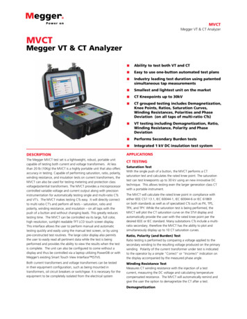
SMRT36Megger Relay Test SystemSMRT36 Relay TesterApplications Selection Guide34Protective Relaysby IEEE Device #5216171671589101112131. Binary Outputs 1 and 2: Rated for 300 V at 8 Amps.2. Binary Inputs 1 and 2: Rated 5 to 300 V AC/DC.4. Voltage Outputs: Up to 3 channels 300 V at 150 VA,convertible to currents 15 A at 120 VA per phase.nnn21Distance SinglePhasennn21Distance ThreePhase Open Deltann21Distance ThreePhase wye24Volts/Hz25Synchronizing32Directional PowerSingle Phase32Directional PowerThree Phase(Open Delta)nnnnnnnnnnnn(n)nDC Under/OverVoltage/Currentnnn40Loss of Fieldnnn46Phase BalanceCurrentnnnNegative SequenceOvercurrentnnn(n)n46N5. Current Outputs: Up to 3 channels 60 Amps at 300 VA perphase. Up 180 Amps at 900 VA single phase.SMRT36ThreeChannelsTime Delay37/763. Transducer Input: (Optional) DC voltage and DC milliampinput terminals.SMRT36TwoChannels227/59 Under/Over Voltage14SMRT36SingleChannel6. USB 2.0 Interface: Communication and control port.47Phase SequenceVoltage(Open Delta)7. Additional Binary Inputs: Provides 8 additional monitorcircuits.50InstantaneousOvercurrentUp to75 AmpsUp to150 AmpsUp to225 Amps8. Rugged Case: Fiberglass reinforced plastic.51Time DelayOvercurrentUp to35 AmpsUp to70 AmpsUp to105 Amps55Power Factornnn60Voltage/CurrentBalance(Open ound DirectionalOvercurrentnnn78Out of Stepnnn79Reclosingnnn81Frequencynnn85Carrier or Pilot Wirennn87Differentialnnn91Voltage Directional(Open Delta)(n)n92Voltage and PowerDirectional(Open Delta)(n)n94Trippingnn9. PC/OUT: Ethernet Port is the primary PC connection port.Ethernet Port used to chain multiple SMRT units together forsynchronous multi-unit operation.10. Additional Binary Outputs: Adds 4 outputs. Binary Outputs 3and 4 are rated for 300 V AC/DC, 8 amperes. Binary Outputs 5and 6 are high speed and have an AC/DC voltage rating of 400volts peak, 1 ampere.67N11. IN/61850: This port may also be used for connecting to the IEC61850 substation bus for testing IEC 61850 devices.12. STVI: Ethernet Port is a PoE (Power over Ethernet) port and isused to connect to the STVI for manual control.13. Battery Simulator: Variable 10 to 250 Volts DC output at 100Watts (4 amperes maximum).14. Incoming Power/Line Cord Socket: 100 to 240 V,50/60 Hz.15. POWER ON/OFF Switch: Illuminates when power is on.16. Protective Earth Ground Jack.17. Bluetooth: Bluetooth provides wireless control.3n
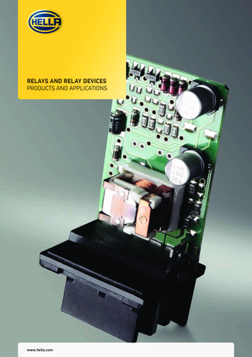
SMRT36Megger Relay Test SystemCurrent Amplifier - Extended Power RangeThe SMRT current amplifier provides a unique flat power curve from4 to 30 Amperes per phase to permit testing of electromechanicalhigh impedance relays, and other high burden applications, with anextended operating range up to 60 Amperes at 300 VA rms.Specifications1Input PowerThe input voltage rating varies depending upon the style number.Universal units, the input voltage may be from 100 to 240 VAC, 10%, 50/60 Hertz. CE Marked units, the input voltage may befrom 220 to 240 VAC, 10%, 50/60 Hertz. Total maximum outputpower will be limited for CE marked units . Input current requiredvaries with the number of output modules in use, load, and inputvoltage value. With three VIGENS, the maximum input power is1800VA.AC Voltage OutputOutputs are rated with the following Ranges:Output VoltsPowerMax I30 Volts150 VA5 Amps150 Volts150 VAVariable2300 Volts150 VA0.5 AmpsDC 150 WattsDuty Cycle: ContinuousOutputsAll outputs are independent from sudden changes in mains voltageand frequency, and are regulated so changes in load impedance donot affect the output. All amplifier outputs are isolated or floating.The SMRT units can be ordered with the amplifier common returnstied to chassis ground as an option.With two voltages in seriesThe output voltage and power doubles to provide 600 volts at300 VA.Output Current SourcesThe SMRT36 with three VIGEN modules can provide up tosix current sources; three high current/high power, and threeconvertible channels providing lower current/high power. The perchannel output current and power ratings are specified in AC rmsvalues and peak power ratings.Output Current1 Ampere4 Amperes15 Amperes30 Amperes60 AmperesDC 200 WattsPower15 VA200 VA (282 peak)200 VA (282 peak)200 VA (282 peak)300 VA (424 peak)Max V/Duty Cycle15.0 Vrms Continuous50.0 Vrms Continuous13.4 Vrms Continuous6.67 Vrms Continuous5.00 Vrms 90 CyclesWith three currents in parallel:Output Current12 Amperes45 Amperes90 Amperes180 Amperes"PowerV" Voltage Amplifier Output Power CurvesPowerMax V/Duty Cycle600 VA (848 peak) 50.0 Vrms Continuous600 VA (848 peak) 13.4 Vrms Continuous600 VA (848 peak) 6.67 Vrms Continuous900 VA (1272 peak) 5.00 Vrms 90 Cycles“PowerVTM” Voltage Amplifier - Extended Power RangeThe SMRT voltage amplifier provides a flat power curve from 30to 150 Volts in the 150V range to permit testing of high currentapplications such as panel testing.Voltage Amplifier in Current Mode:The voltage amplifier is convertible to a current source with thefollowing output capability. Output power ratings are specified inrms values and peak power ratings.Output CurrentPowerMax VDuty Cycle5 Amperes150 VA30.0 VrmsContinuous(212 peak)15 Amperes120 VA8.0 Vrms90 CyclesPhase AngleRanges: 0.00 to 359.99 degrees, Counter Clock Wise, or ClockWise rotation, or 0.00 to 180.00 degreesAccuracy: 0.02 typical, 0.25 max at 50/60 HzCurrent Amplifier Output Power CurveWith two currents in series:The compliance voltage doubles to provide 4.0 Amperes at 100Volts rms.12Megger reserves the right to change product specifications at any time.PowerVTM voltage amplifier output current varies depending on the voltage setting on the 150 Volt range, see curve.4
SMRT36Megger Relay Test SystemBattery SimulatorThe SMRT36 with the P (Plus) option includes a battery simulatorwith a variable DC output voltage ranging from 10 to 250 Volts at100 Watts, 4 Amps max, providing capability to power up relayswith redundant power supplies. Voltage output is controlled viathe Smart Touch-View Interface, or through AVTS software. TheSMRT36 with the N option does not include a battery simulator.FrequencyThe output modules provide a variable frequency output with thefollowing ranges and accuracy.RangesDC0.001 to 1000.000 HzOutput amplifiers can provide transient signals with a range ofDC to 10 kHz for transient playback using COMTRADE files.Resolution*: .0001/.001 HzFrequency Accuracy:2.5 ppm typical25 ppm 0 to 50 C, at 50/60 Hz MaximumWaveform GenerationEach output channel can generate a variety of output waveformssuch as: DC; sine wave; sine wave with percent harmonics at variousphase angles; half waves; square waves with variable duty cycles;exponential decays; periodic transient waveforms from digital faultrecorders, relays with waveform recording capability or EMTP/ATP programs, which conform to the IEEE C37.111 COMTRADEstandard format.Total Harmonic DistortionLess than 0.1% typical, 2% maximum at 50/60 HzTimerThe Timer-Monitor Input is designed to monitor and time-taginputs, like a sequence of events recorder. In addition, the binaryinput controls enable the user to perform logic AND/OR functions,and conditionally control the binary output relay to simulate circuitbreaker, trip, reclose and carrier control operation in real-time. TheTimer function displays in Seconds or Cycles, with the followingrange and resolution:Seconds: 0.0001 to 99999.9MeteringMeasured output quantities such as AC Amperes, AC Volts, DCVolts or DC Amperes, and Time may be simultaneously displayedon the large, color TFT LCD touch screen. The AC and DC outputsdisplay the approximate voltage/current output prior to initiation ofthe outputs. All accuracies stated are from 10 to 100% of the rangeat 50/60Hz.AC Voltage AmplitudeAccuracy: 0.05 % reading 0.02 % range typical, 0.15 % reading 0.05 % range maximumResolution: .01Measurements: AC RMSRanges: 30, 150, 300V(Auto Ranging)Cycles: 0.01 to 99999.9(Auto Ranging)Accuracy: 0.001% of reading, typical. 2 least significant digit, 0.005% of reading from 0 to 50 C maximumAC Current AmplitudeAccuracy: 0.05 % reading 0.02 % range typical, 0.15 % reading 0.05 % range maximumResolution: .001/.01Measurements: AC RMSRanges: 30, 60ABinary Input – Start/Stop/Monitor GateTo monitor operation of relay contacts or trip SCR, continuity lightis provided for the input gate. Upon sensing continuity the lamp willglow. In addition to serving as wet/dry contacts the Binary Inputsmay be programmed to trigger binary output sequence(s).Input Rating: up to 300 V AC/DCDC Voltage AmplitudeAccuracy: 0.1% range typical,0.25% range maximumResolution: .01Measurements: RMSRanges: 30, 150, 300VBinary Output RelaysSMRT36 has independent, galvanically isolated, output relaycontacts to accurately simulate relay or power system inputs tocompletely test relays removed from the power system. The binaryoutput simulates normally open / normally closed contacts fortesting breaker failure schemes. The binary output can be configuredto change state based on binary input logic.High Current Output Relays: The first two VIGEN Modules have1 each and the P option add 2 more.AC Rating: 400 V max., Imax: 8 amps, 2000 VA max.DC Rating: 300 V max., Imax: 8 amps, 80 WResponse Time: 10msHigh Speed Output Relays: SMRT36 P Option adds 2AC/DC Rating: 400 V peak, Imax: 1 ampResponse Time: 1ms typicalDC Current AmplitudeAccuracy: 0.05 % reading 0.02 % range typical, 0.15 % reading 0.05 % range maximumResolution: .001/.01Measurements: RMSRanges: 30A5
SMRT36Megger Relay Test SystemConvertible Source in AC Current ModeAccuracy: 0.05 % reading 0.02 % range typical, 0.15 % reading 0.05 % range or 12.5 mA whichever is greaterResolution: .001Measurements: AC RMSRange: 5, 15AElectromagnetic CompatibilityEmissions:EN 61326-2-1, EN 61000-3-2/3,FCC Subpart B of Part 15 Class AImmunity:ProtectionVoltage outputs are protected from short circuits and thermallyprotected against prolonged overloads. Current outputs areprotected against open circuits and thermally protected againstprolonged overloads.The DC IN input terminalsRange:0 to 10 V DC0 to 20 mA DCAccuracy: 0.02% Typical 0.05% Max FSMeasurements: AverageCommunication InterfacesEthernet (2)USB 2.0Bluetooth (optional)DC IN Inputs (Optional Transducer Feature)DC IN VoltsRange: 0 to 10 V DCAccuracy: 0.001% reading 0.005% range Typical 0.003% reading 0.02% range MaxResolution: .001Measurements: AverageSoftwareAVTS – STVI BasicEvery unit comes with AVTS Basic software and the PC versionof the STVI Basic software packages. AVTS Basic version includesOnline Vector control (for single and multi-state timing tests), OnlineRamp control (for automatic ramping of voltage, current, phaseangles or frequency) and Online Click-On-Fault (for dynamic tests ofimpedance relays). Test results may be exported directly to MicrosoftWord. AVTS software includes a database for saving test results,which can also provide the necessary information needed for systemreliability audits. See AVTS bulletin for more information.DC IN AmperesRange: 0 to 1 mA DC4 to 20 mA DCAccuracy: 0.001% reading 0.005% range Typical 0.003% reading 0.02% range MaxResolution: .001Measurements: AverageThe PC version of the STVI software includes the ability to bring allSTVI test data (from other STVI units) into file folders for retrieval,review and printing whenever needed. See STVI bulletin for moreinformation.EnvironmentalOperating Temperature: 32 to 122 F (0 to 50 C)Storage Temperature: -40 to 158 F (-40 to 70 C)Relative Humidity: 5 - 90% RH, Non-condensingAVTS AdvancedUnit EnclosureThe SMRT unit comes housed in a rugged, virtually indestructible,lightweight and ergonomic enclosure. It features a large oversizedrubber cushioned handle, and removable lid for use in tight spaces.The AVTS Advanced version includes all the feature in AVTS Basicplus the powerful Test Editor, Dynamic Control (includes dynamicend-to-end testing capability, and waveform recording capability),ASPEN OneLiner or Electrocon CAPE SS1 File Converter fordynamic testing, and easy to use programming Tools for creatingand editing test modules. See AVTS bulletin for more information.DimensionsWith the lid on:14.2 W x 7.6 H x 12.0 D in.(360 W x 194 H x 305 D mm)With the lid off:14.2 W x 7.2 H x 12.0 D in.(360 W x 180 H x 305 D mm)IEC Enclosure Rating: IP30AVTS ProfessionalThe AVTS Professional version includes all of the features of theBasic and Advanced versions plus some other powerful test toolsand features. It includes the DFR Waveform Viewer, One-Touch Test for fully automatic tests, Modbus communication testcapability, and Waveform Digitizer to digitize scanned waveforms ofelectromechanical over current time curves. See AVTS bulletin formore information.WeightWith the transit lid on: 27.9 lb. (12.55 kg)With the transit lid off: 25.8 lb. (11.6 kg)IEC 61850 GOOSEConformance StandardsSafety:EN 61010-1Shock:MIL-PRF-28800F (30 g/11ms half-sine)IEC 60068-2-27 (15 g/11 ms half-sine)Vibration:MIL-PRF-28800F (10-500 Hz, 2.05 g rms)IEC 60068-2-6 (10-150 Hz, 2 g)Transit Drop:MIL-PRF-28800F (10 drops, 46 cm), ISTA 1AEN 61000-4-2/3/4/5/6/8/11The SMRT with the GOOSE enabled, in conjunction with the MeggerGOOSE Configurator (MGC) software, can be used in the testing orcommissioning of IEC 61850 compliant devices. See AVTS bulletinfor more information.6
SMRT36Megger Relay Test SystemOrdering InformationStyle Number IdentificationModel SMRT36 -0Test Leads Option1 With Leads0 Without LeadsVoltage/Current ModulesEnter 1, 2 or 3Reserved for Future UseBase Unit OptionsN No Extra Binary I/OP Plus Binary I/O & Battery SimulatorHardware OptionsS Standard unitT TransducerSmart Touch View Interface Option1 With STVI;0 WithoutIEC61850 Option1 With IEC 61850 GOOSE0 WithoutCommon Returns OptionF Floating Ungrounded Common ReturnG Grounded Common ReturnsC CE Mark, 220-240V Input, FloatingE CE Mark, 220-240V Input, GroundedPower Cord OptionA North American Power CordI International Power CordE Continental Europe Power CordU United KingdomBluetooth Option1 With Bluetooth0 WithoutDescription of Software OptionsIncluded SoftwarePart NumberAVTS Basic with STVI Application CD81302Software OptionsAVTS Basic with IEC 61850 Megger GOOSE Configurator, and STVI Application CDAVTS Advanced with STVI Application CD1002-10381570AVTS Advanced Test with IEC 61850 Megger GOOSE Configurator, and STVI Application CDAVTS Professional with STVI Application CD1002-10681571AVTS Professional Test with IEC 61850 Megger GOOSE Configurator, and STVI Application CD1002-102Descriptions of Hardware OptionsPower Cord Option: Customers can choose which type of powercord they want the unit to come with. A Option – NEMA 5-15 to IEC60320 C13 connectors,UL & CSA approved for countries with NEMA outlets. I Option - International color coded wires (light blue, brown andgreen with yellow stripe) insulation jacket stripped ready for maleconnector with IEC 60320 C13 connector.CE marked. E Option - CEE 7/7 “Schuko” plug to IEC 60320 C13 connectoris CE marked. U Option - United Kingdom power cord with IEC 60320 C13connector, and 13 Amp fuse. CE Marked.Voltage/Current Module: The SMRT36 unit can have up to a totalof 3 voltage/current modules. Enter the number of desired Voltage /Current modules 1, 2 or 3.Future: 0, Reserved for future use.Base Unit Options: The first two channels provide 1 binary inputand 1 binary output each. Enter N for No extra binary I/O or batterysimulator. For the user who requires the extra binary inputs, outputsand/or the battery simulator enter P for Plus option.Smart Touch View Interface Option: Enter the number 1 for theunit to come with the STVI, or enter the number 0 for without.Common Returns Option: The floating returns option providesindependent, isolated return terminals for each output channel.The grounded common returns option, the return terminals areinterconnected internally and connected to chassis ground. The CEMark C and E units are designed to operate with an input voltage of220 to 240 Volts. The F and G units are designed to operate with aninput of 100 to 240 V.Bluetooth Option: For customers who wish to have a wirelesscontrol of the SMRT unit, enter the number 1 for the unit to comewith the Bluetooth option installed. Enter 0 for without.IEC 61850 Option: The SMRT36 in conjunction with the MeggerGOOSE Configurator (MGC) software can be used in the testingor commissioning of IEC 61850 compliant devices. In order for theSMRT36 to be able to subscribe as well as publish GOOSE messages,the IEC 61850 feature needs to be enabled. Enter the number 1 forthe unit to come with the IEC 61850 option enabled. Enter 0 for theunit without IEC 61850 enabled.Bluetooth Option: For customers, who wish to have a wirelesscontrol of the SMRT unit, enter the number 1 for the unit to comewith the Bluetooth option, or enter 0 for without.7
SMRT36Megger Relay Test SystemTest Leads and AccessoriesAll units come with a power cord (see Power Cord option), andEthernet communication cable, and instruction manual CD. Allother accessories varies depending on the options selected, seeTable of Accessories.Hardware Options: S for Standard hardware. T for Transducerenabled.Test Leads Option: Enter the number 1 for the unit to come withTest Leads. Enter 0 for the unit without Test Leads.DescriptionIncluded Standard AccessoriesPart NumberPower Cord - Depending on the style number, the unit will come with one of the following,Line cord, North American620000Line cord, Continental Europe with CEE 7/7 Schuko Plug50425Line cord, International color coded wire15065Line cord, United Kingdom90002-989Ethernet cable for interconnection to PC, 210cm (7 ft.) long (Qty. 1 ea)90003-684Instruction manual CD80989Table of AccessoriesAccessories are supplied with the selection of the Test Leads Option,and/or the Binary Input / Output / Battery Simulator Option, and/orthe STVI Option. With the Test Leads Option the number and typeof leads varies depending on the number of channels ordered. Ifdesired, Test Leads and Accessories can be ordered individually, seedescription and part numbers below.STVI, orBinary I/OBat SIM, orTest LeadsOptionsOne (1)VoltageCurrentModuleTwo (2)VoltageCurrentModulesThree (3)VoltageCurrentModulesBinary I/O,BatterySimulatorOptionSleeved Pair of Test Leads: Keeps the test leads in pairsand from getting entangled.Sleeved Test Leads, one red, one black, 200 cm (78.7”)long, 600 V, 32 Amperes CAT II.Qty. 3 pr.Part No.2001-394Qty. 6 pr.Part No.2001-394Qty. 2 pr.Part No.2001-394Qty. 3 pr.Part No.2001-394Cable/Spade Lug Adapter (Small): Small lug fit most newrelay small terminal blocks.Lug adapter, red, 4.1 mm, use with test leads up to 1000V/ 20 Amps CAT II.Qty. 3 ea.Part No.684004Qty. 6 ea.Part No.684004Qty. 12ea.Part No.684004Qty. 3 ea.Part No.684004Lug adapter, black, 4.1 mm, use with test leads up to 1000V/ 20 Amps CAT II.Qty. 3 ea.PartNumber684005Qty. 6 ea.PartNumber684005Qty. 12ea.PartNumber684005Qty. 3 ea.PartNumber684005Qty. 2 ea.PartNumber2001-573Qty. 4 ea.PartNumber2001-573Optional Accessories DescriptionsAccessory Carry Case: Use to carry power cord, Ethernetcable, Optional STVI and test leads.Qty. 1 ea.Part No.2001-487Jumper Lead: Used to common returns together on unitswith floating ground returns, or parallel of current channels.Jumper lead, black, 12.5 cm (5”) long, use with voltage /current outputs, 600 V, 32 Amps CAT II.Sleeved Combination Voltage Test Leads: Keeps the testleads from getting entangled. Three common leads connectto the test set, which are interconnected down to one blackcommon to connect to the relay under test. Sleeved ThreePhase Test Leads, three red and black, 200 cm (78.7”) long,600 V, 32 Amperes CAT II.Qty. 1 ea.PartNumber2001-395Sleeved Combination Current Test Leads: Keeps the testleads from getting entangled. Three pairs of leads connectto the test set, with three pairs to connect to the relayunder test. Sleeved Three Phase Test Leads, three red andblack, 200 cm (78.7”) long, 600 V, 32 Amperes CAT II.Qty. 1 ea.PartNumber2001-396Note that the sleeved combination leads only come with the three module configuration.8
SMRT36Megger Relay Test SystemDescriptions of SoftwareIncluded Software – Every unit comes with AVTS Basic and the PCversion of the STVI Basic Test software packagesAVTS Basic with STVI ApplicationSoftware (PC Version)AVTS Professional with STVI ApplicationProfessional Test includes all of the features of AVTS AdvancedTest version plus the following additional specialized test tools. TheDFR Waveform Viewer and Playback tools are used for viewing andanalyzing IEEE C37.111 COMTRADE Standard files from digital faultrecorders and microprocessor based relays. The DFR WaveformViewer includes tools to recreate the analog and digital channels forplayback into protective relays for troubleshooting or evaluation. Itincludes the capability to extend the prefault data as well as startthe timer associated with the event to time relay operation. Theseplayback test files can also be used in end-to-end tests to recreatethe transient event and evaluate the protection scheme. Test filescreated in Professional can be used with Advanced Test and Basic.Also included is the One-Touch Test
The SMRT36 test system has the ability to be manually controlled with Megger's new Smart Touch View Interface (STVI). The STVI, with its large, full color, high resolution, TFT LCD touch screen allows the user to perform manual, steady-state and dynamic testing quickly and easily using the manual test screen, as well as