Transcription
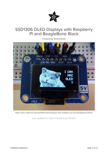
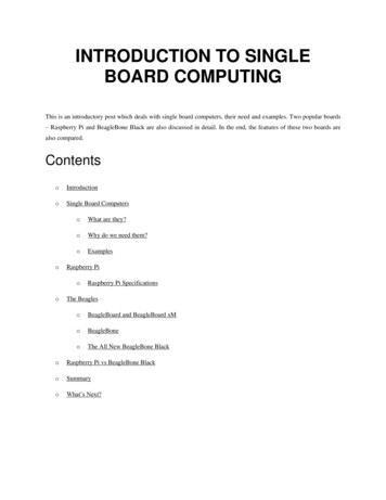
BeagleBone Black Expansion Board User ReferenceBeagleBone Black Expansion board designed by ChipSee. It can supportBeaglebone and Beaglebone black at the same time. And it has two Versions:Capacitive Touch Version and Resistive Touch Version. Hardware features:1. Display:7 Inch LCD,1024*600 Pixel;2. Touch:Five Point Capacitive touch, Covered with Amorplate Glass (Or ReisistiveTouch);3. Audio:1 Audio out,1 Mic In(Can change to Line in by change resistor);4. RS232:2 Channel;5. RS485:2 Channel;6. CAN:1 Channel;7. Buzzer:1;8. User Key:5;9. User LED:2;10. Three-Axis Digital Accelerometer.Figure 1. BeagleBone Black Expansion Board(Capacitive,Android 4.1)
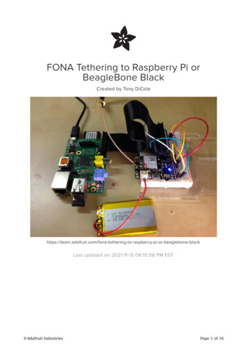
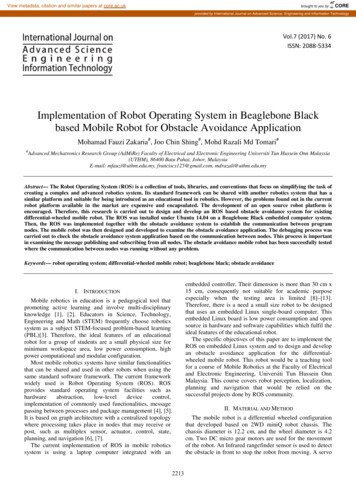
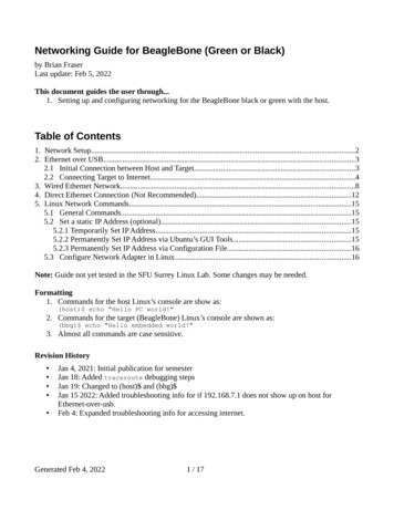
Figure 2. Back-Side View (Capacitive)1. How to connect Expansion board with Beaglebone and BeagleBone BlackWhen connect the Expansion board with BeagleBone and BeagleBone Black,Figure 3 shows the right connect direction. If connect on the wrong direction, theBeaglebone Black can’t be push down to connect tightly: The LAN connector onBeaglebone Black will conflict with the Audio connector on the Expansion board.Figure 32. How to connect Power to the SystemBeagleBone and BeagleBone Black use 5V DC power Input, the expansion boarduse 5V DC power also. When the Expansion board connect with the the BeagleBone
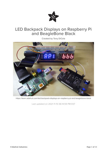
and Beaglebone black,the Power connector on BeagleBone black will be hide by theRS485 connector. Customer can provide 5V power to the power connector on theExpansion board connector P4 ONLY as Figure 4 shows. This 5V power will beconnect to Beaglebone Black on the Expansion board.5V/2A power adapter will benecessary.Figure 43. How to change Boot MethodBeaglebone Black can be changed boot method by push the Button S2. Whenpushed button S2 when system power on, BeagleBone Black will boot from uSD card,or it will boot from eMMC by default.When connect with expansion board, the Button S2 on the Beaglebone blackwill be hide and not easy to touch. The Expansion board connect this boot signal toswitch SW8 as Figure 5 shows. When user switch it to upside, the system will bootfrom uSD card, when user switch it to downside, the system will boot from eMMC.
Figure 54. Power and Reset ButtonBeagleBone Black use Button S3 as Power button, Expansion board connect thissignal to Button SW6 as Figure 6 shows. So the Expansion board button SW6 willhave the same effect with S3 on the BeagleBone Black.BeagleBone Black use Button S1 as Reset button, Expansion board connectthis signal to Button SW7 as Figure 5 shows. So the Expansion board button SW7 willhave the same effect with S1 on the BeagleBone Black.Figure 65. Use Keys and user LEDBeagleBone Black Expansion board have add 5 user keys as SW1 to SW5 asFigure 6 shows, User can define the key function in software, ChipSee have define it
in Android 4.1 as “HOME”,”BACK”,”MENU”,”VOLUME UP”,”VOLUME DOWN”.BeagleBone Black Expansion Board add two user LEDs as Figure 7 shows. Usercan define its function in software.Figure 76. Audio Input and OutputBeagleBone Black Expansion board have audio input and output as Figure 8shows. The expansion board use standard 3.5mm connector. Blue connector P8 isoutput, Pink Connect P9 is input.User can connect the output to any other speaker. As for the Input, it’s “MIC in”,NOT “Line In”, that means user can connect Microphone to the connector directly.Figure 87. About the RS232 , RS485 and CAN on Expansion board.The Expansion board have add RS232 ,RS485, CAN function to the connector
P10 and P12 as Figure 2 shows.DB9 Connector P10 connect to the CPU UART1:Pin Number2351,4,6,7,8,9DefinitionTXDRXDGNDNot ConnectedCPU FunctionUART1, CPU PIN D15and D16Connector P12 definition:Pin Number123456789101112DefinitionGNDCAN0 LCAN0 HRS485 2 RS485 2RS485 1 RS485 1RS232 2 TXDRS232 2 RXDRS232 1 TXDRS232 1 RXD 5VCPU FunctionDCAN0, CPU PIN D17 andD18UART4, CPU PIN T17 andU17UART2, CPU PIN A15 andB17UART1, CPU PIN D15 andD16Be Attention:a) The RS232 1 signal have been connect to the DB9 connector P10 and connectorP12 Pin 10 and Pin 10 at the same time. As for this function, you can use oneconnector one time.b) The RS232 2 signal and RS485 1 signal use the same UART2 signal from CPU, sothese two functions User can use only one at one time. That means, if user usedRS232 2 function,user can’t use RS485 1,if user used RS485 1 function, usercan’t use RS232 2 function.c)BeagleBone black use UART0 as the default DEBUG signal output, but it’s TTLsignal output. ChipSee Software changed the Debug signal to UART1 by default.So this can make user very easy to use the Debug.
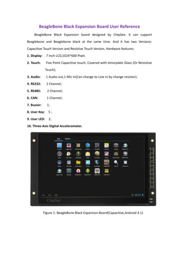
8. Mechanical Dimension:As Figure 9 shows. The mounting hole is 3mm Inner diameter.Figure 99. Product VideoAndroid 4.1http://youtu.be/FebYqMws0g4Windows CE 6.0http://youtu.be/S2Ttujf6cWUChipSee Information Technology Co.,LtdRoom 1004, Mansion Haojing 3#,Zhichun Road 108Haidian District, Beijing, China,100080TEL: 86-10-62561127E-Mail: Service@chipsee.com
and Beaglebone black,the Power connector on BeagleBone black will be hide by the RS485 connector. Customer can provide 5V power to the power connector on the Expansion board connector P4 ONLY as Figure 4 shows. This 5V power will be connect to Beaglebone Black on the Expansion board.5V/2A power adapter will be necessary. Figure 4 3.