Transcription
SSD1306 OLED Displays with RaspberryPi and BeagleBone BlackCreated by Tony lays-with-raspberry-pi-and-beaglebone-blackLast updated on 2021-11-15 06:14:26 PM EST Adafruit IndustriesPage 1 of 12
Table of ContentsOverview3Wiring3 344667Raspberry PiI2CSPIBeagleBone BlackI2CSPIUsage8 Dependencies Usage8889 Adafruit IndustriesPage 2 of 12
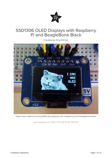
OverviewThis code is discontinued - Check out our newer tutorial at - ts/python-wiringAre you looking for a bright graphical display to use with you Raspberry Pi orBeagleBone Black project? Consider using one of the SSD1306-based OLED displays(https://adafru.it/dAZ), with the SSD1306 Python library (https://adafru.it/dB0)!Although they're small (only an inch or so in size), these displays produce a beautifuland crisp 128x32 or 128x64 pixel image. Connecting the display to a Raspberry Pi orBeagleBone Black is easy too thanks to the display's 3.3 volt support, and I2C or SPIinterface.This guide will walk you through how to connect the display to a Raspberry Pi orBeagleBone Black, and how to install and use the SSD1306 Python library. Before youget started it will help to read the guide on their usage (https://adafru.it/dAZ) so youknow how the displays are assembled and configured. Make sure your Raspberry Pi isrunning the latest Raspbian (https://adafru.it/dpb) or Occidentalis (https://adafru.it/dvg)operating system, or your BeagleBone Black is running the official Debian (https://adafru.it/dvh) or a Debian-based operating system like Ubuntu.WiringThis code is discontinued - Check out our newer tutorial at - ts/python-wiringRaspberry PiYou can hook up an OLED to the Raspberry Pi using either the Pi's I2C or SPIinterface. If your OLED supports both I2C and SPI, make sure to check how the solderjumpers are configured to expose the right interface (https://adafru.it/dB1).In general, I2C uses fewer pins but is slower. SPI is way fast, but requires a bunchextra pins. Choose your adventure based on your needs! Adafruit IndustriesPage 3 of 12
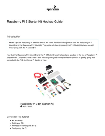
I2CTo use the Pi with an I2C display wire it up as follows:NOTE: Make sure to enable I2C on your Pi (https://adafru.it/dEO) before wiring it up! Connect display ground to Raspberry Pi ground (black wire). Connect display VIN to Raspberry Pi 3.3 volt (red wire). Connect display RST to Raspberry Pi GPIO 24 (blue wire). You can alternativelyuse any free digital GPIO pin for the reset pin. Connect display SCL to Raspberry Pi SCL (purple wire). Connect display SDA to Raspberry Pi SDA (orange wire).SPITo use the Pi with an SPI display, wire it up as follows: Adafruit IndustriesPage 4 of 12
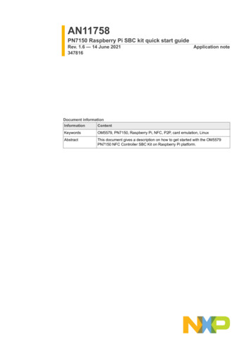
Connect display ground to Raspberry Pi ground (black wire). Connect display VIN to Raspberry Pi 3.3 volt (red wire). Connect display CS to Raspberry Pi CE0 (yellow wire). Connect display RST to Raspberry Pi GPIO 24 (blue wire). You can alternativelyuse any free digital GPIO pin for the reset pin. Connect display DC to Raspberry Pi GPIO 23 (cyan wire). You can alternativelyuse any free digital GPIO pin for the DC pin. Connect display CLK to Raspberry Pi SCLK (orange wire). Connect display Data to Raspberry Pi MOSI (purple wire).Note that the wiring above will use the Raspberry Pi's hardware SPI bus tocommunicate with the display. If you haven't done so already with your Pi, make sureto edit the blacklist.conf file (https://adafru.it/dvD) to comment the line which disablesSPI. Reboot your Pi and you should see the files /dev/spidev0.0 and /dev/spidev0.1 are now available.Using hardware SPI is great for getting the fastest response from the display, howeverif you need more flexibility with pin usage you can use a software-based SPIimplementation with any 5 free digital GPIO pins. See the example code usage on thenext page for more information about configuring software SPI. Adafruit IndustriesPage 5 of 12
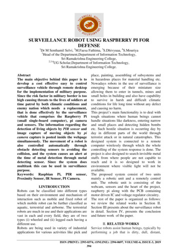
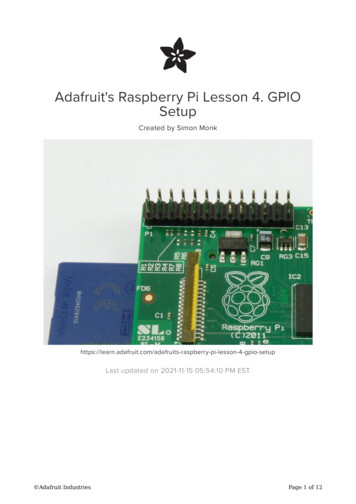
BeagleBone BlackJust like with the Raspberry Pi, you can use an OLED display with the BeagleBoneBlack over either the SPI or I2C interface.I2CTo use the BeagleBone Black with an I2C display, wire it up as follows: Connect display ground to BeagleBone Black ground (black wire). Connect display VIN to BeagleBone Black 3.3 volt (red wire). Connect display RST to BeagleBone Black P9 12 (blue wire). You canalternatively use any free digital GPIO pin for the reset pin. Connect display SCL to BeagleBone Black I2C2 SCL pin P9 19 (purple wire). Connect display SDA to BeagleBone Black I2C2 SDA pin P9 20 (orange wire).Note that the BeagleBone Black has two I2C interfaces and this wiring will use the /dev/i2c-1 interface. Make sure there aren't any device tree overlays loaded (https://adafru.it/dp6) which use these I2C pins for other purposes. The default BeagleBoneBlack device tree configuration with no overlays loaded will expose the necessary I2Cinterface for the wiring above. Adafruit IndustriesPage 6 of 12
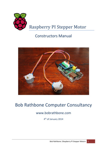
SPITo use the BeagleBone Black with an SPI display, wire it up as follows: Connect display ground to BeagleBone Black ground (black wire). Connect display VIN to BeagleBone Black 3.3 volt power (red wire). Connect display CS to BeagleBone Black SPI0 CS0 pin P9 17 (yellow wire). Connect display RST to BeagleBone Black P9 12 (blue wire). You canalternatively use any free digital GPIO pin for the reset pin. Connect display DC to BeagleBone Black P9 15 (cyan wire). You canalternatively use any free digital GPIO pin for the DC pin. Connect display CLK to BeagleBone Black SPI0 SCLK pin P9 22 (orange wire). Connect display Data to BeagleBone Black SPI0 D1 pin P9 18 (purple wire).Like with the Raspberry Pi, the wiring above assumes using a hardware SPI interfaceon the BeagleBone Black, specifically /dev/spidev1.0. Before you can use this SPIinterface you must enable a device tree overlay (https://adafru.it/dp6) to turn on theSPI pin functionality. The easiest way to enable this device tree overlay is to configurethe BeagleBone Black to load the overlay automatically on boot.With the BeagleBone Black connected to your computer over USB, open the USBmass storage drive named 'boot' and edit the file uEnv.txt on the drive. Add thefollowing line to the file:optargs capemgr.enable partno BB-SPIDEV0 Adafruit IndustriesPage 7 of 12
NOTE: Be careful editing the uEnv.txt file on Windows, as changing the line endingscan cause your BeagleBone Black not to boot and require an OS reinstall! The safestoption is to connect to the BeagleBone Black in a command window and follow thesteps at the end of this page to mount and edit uEnv.txt on the BeagleBone Black (https://adafru.it/dEK).Reboot your device and you should see the files /dev/spidev1.0 and /dev/spidev1.1 now exist.UsageThis code is discontinued - Check out our newer tutorial at - ts/python-wiringDependenciesBefore using the library you will need to make sure you have a few dependenciesinstalled. Connect to your device using SSH and follow the steps below.If you're using a Raspberry Pi, install the RPi.GPIO library by executing:sudo apt-get updatesudo apt-get install build-essential python-dev python-pipsudo pip install RPi.GPIOIf you're using a BeagleBone Black, install the Adafruit BBIO library by executing:sudo apt-get updatesudo apt-get install build-essential python-dev python-pipsudo pip install Adafruit BBIOFinally, on both the Raspberry Pi and Beaglebone Black install the Python ImagingLibrary (https://adafru.it/dvB) and smbus library by executing:sudo apt-get install python-imaging python-smbusNow to download and install the SSD1306 python library code and examples, executethe following commands: Adafruit IndustriesPage 8 of 12
sudo apt-get install gitgit clone https://github.com/adafruit/Adafruit Python SSD1306.git (https://adafru.it/dEH)cd Adafruit Python SSD1306sudo python setup.py installUsageInside the examples subdirectory you'll find python scripts which demonstrate theusage of the library. To help you get started, I'll walk through the shapes.py codebelow:import timeimport Adafruit GPIO.SPI as SPIimport Adafruit SSD1306import Imageimport ImageDrawimport ImageFontFirst a few modules are imported, including the Adafruit SSD1306 module whichcontains the OLED display driver classes. You can also see some of the PythonImaging Library modules like Image, ImageDraw, and ImageFont being imported.# Raspberry Pi pin configuration:RST 24# Note the following are only used with SPI:DC 23SPI PORT 0SPI DEVICE 0######Beaglebone Black pin configuration:RST 'P9 12'Note the following are only used with SPI:DC 'P9 15'SPI PORT 1SPI DEVICE 0Next some configuration values are set depending on the platform. If you're using theBeagleBone Black you'll need to comment the Raspberry Pi pin configuration linesand uncomment the BeagleBone Black configuration lines.If you want to change to a different RST or DC pin, you can update the RST and DCpin values respectively. You can also change the SPI port and device, but Irecommend sticking with those interfaces above as they've been tested and areknown to work.# 128x32 display with hardware I2C:disp Adafruit SSD1306.SSD1306 128 32(rst RST) Adafruit IndustriesPage 9 of 12
# 128x64 display with hardware I2C:# disp Adafruit SSD1306.SSD1306 128 64(rst RST)# Alternatively you can specify an explicit I2C bus number, for example# with the 128x32 display you would use:# disp Adafruit SSD1306.SSD1306 128 32(rst RST, i2c bus 2)# 128x32 display with hardware SPI:# disp Adafruit SSD1306.SSD1306 128 32(rst RST, dc DC, spi SPI.SpiDev(SPI PORT,SPI DEVICE, max speed hz 8000000))# 128x64 display with hardware SPI:# disp Adafruit SSD1306.SSD1306 128 64(rst RST, dc DC, spi SPI.SpiDev(SPI PORT,SPI DEVICE, max speed hz 8000000))####Alternatively you can specify a software SPI implementation by providingdigital GPIO pin numbers for all the required display pins. For exampleon a Raspberry Pi with the 128x32 display you might use:disp Adafruit SSD1306.SSD1306 128 32(rst RST, dc DC, sclk 18, din 25, cs 22)Below the configuration values is the display class setup. There are two classes youcan create, SSD1306 128 32 or SSD1306 128 64. The SSD1306 128 32 classrepresents a 128x32 pixel display, and the SSD1306 128 64 class represents a 128x64 pixel display.Along with the size of the display you also configure what interface the display usesin these lines. The first couple examples use the I2C interface and only need tospecify an RST pin. Internally the SSD1306 library will look up the default I2C busnumber for the platform and use it--if you've followed the wiring in this guide youshould be all set! However if you need to explicitly control the I2C bus number, thethird example shows how to specify it with an i2c bus parameter.The last three examples show how to configure the SPI interface. For hardare-basedSPI you only need to specify the RST pin, DC pin, and hardware SPI device. Use oneof these examples if you've followed the wiring in this guide. However if you want touse a software-based SPI interface, the last example shows how to specify each SPIpin for a Raspberry Pi (for a BeagleBone Black just change the pin values based onthe pins you're using).Uncomment the appropriate display line based on the size of your display and theinterface you're using to talk to the display. The code assumes you're using a 128x32pixel display that's communicating over hardware I2C, however if you're using adifferent display or protocol uncomment the appropriate line. Make sure to commentall the other lines that aren't being used!# Initialize library.disp.begin()# Clear display.disp.clear()disp.display() Adafruit IndustriesPage 10 of 12
# Create blank image for drawing.# Make sure to create image with mode '1' for 1-bit color.width disp.widthheight disp.heightimage Image.new('1', (width, height))# Get drawing object to draw on image.draw ImageDraw.Draw(image)# Draw a black filled box to clear the image.draw.rectangle((0,0,width,height), outline 0, fill 0)The next bit of code will initialize the display library, clear the display, and configure aPIL drawing class to prepare for drawing graphics. Notice that the image buffer iscreated in 1-bit mode with the '1' parameter, this is important because the display onlysupports black and white colors.# Draw some shapes.# First define some constants to allow easy resizing of shapes.padding 2shape width 20top paddingbottom height-padding# Move left to right keeping track of the current x position for drawing shapes.x padding# Draw an ellipse.draw.ellipse((x, top , x shape width, bottom), outline 255, fill 0)x shape width padding# Draw a rectangle.draw.rectangle((x, top, x shape width, bottom), outline 255, fill 0)x shape width padding# Draw a triangle.draw.polygon([(x, bottom), (x shape width/2, top), (x shape width, bottom)],outline 255, fill 0)x shape width padding# Draw an X.draw.line((x, bottom, x shape width, top), fill 255)draw.line((x, top, x shape width, bottom), fill 255)x shape width paddingOnce the display is initialized and a drawing object is prepared, you can draw shapesand graphics using PIL's drawing commands (https://adafru.it/dfH). The code first doesa little work to scale drawings based on the display size, then it moves left to rightdrawing each shape.# Load default font.font ImageFont.load default()# Alternatively load a TTF font.# Some other nice fonts to try: http://www.dafont.com/bitmap.php#font ImageFont.truetype('Minecraftia.ttf', 8)# Write two lines of text.draw.text((x, top),'Hello', font font, fill 255)draw.text((x, top 20), 'World!', font font, fill 255)Next the code loads a built-in default font and draws a few lines of text. You can alsoload your own TrueType font and use it to render text! Adafruit IndustriesPage 11 of 12
# Display image.disp.image(image)disp.display()Finally the image that was created is written to the display buffer, and the display istold to show its buffer. Remember, every time you make a change to the image thatyou want it to be visible on the display you need to call the image and displayfunctions!That's all there is to the shapes.py code! You can run the code by executing thiscommand in the examples directory:sudo python shapes.pyMake sure to run as root with the sudo command so the program has access to thehardware.If you run the shapes.py example you should see something like this (on a 128x64display):Check out the other examples included in the library, such as animate.py whichdisplays an animated text scroller and image.py which displays an image loaded froma file. Modify the configuration at the top of each example just like you did for the shapes.py example above, then run them just like running shapes.py but substituting theappropriate file name.Enjoy using your OLED display with a Raspberry Pi or BeagleBone Black! If you haveissues or want to contribute to the library, feel free to do so on the library's GitHubhome (https://adafru.it/dB0). Adafruit IndustriesPage 12 of 12
To use the BeagleBone Black with an I2C display, wire it up as follows: Connect display ground to BeagleBone Black ground (black wire). Connect display VIN to BeagleBone Black 3.3 volt (red wire). Connect display RST to BeagleBone Black P9_12 (blue wire). You can alternatively use any free digital GPIO pin for the reset pin.