Transcription
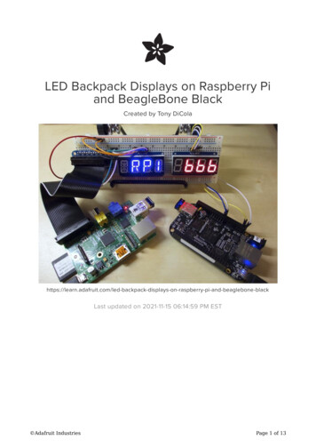
LED Backpack Displays on Raspberry Piand BeagleBone BlackCreated by Tony lays-on-raspberry-pi-and-beaglebone-blackLast updated on 2021-11-15 06:14:59 PM EST Adafruit IndustriesPage 1 of 13
Table of ContentsOverview3Wiring3 Raspberry Pi BeagleBone Black34Usage5 569101112InstallationUsageBicolor Matrix 8x8Bicolor Bar Graph 247 Segment14 Segment Alphanumeric Display Adafruit IndustriesPage 2 of 13
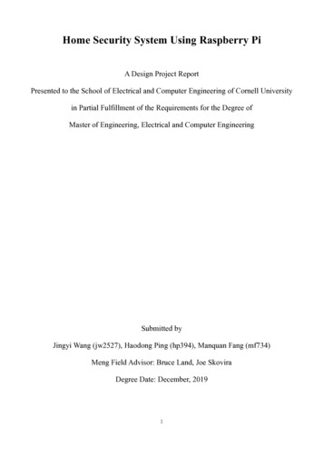
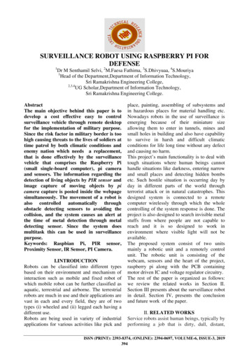
OverviewThe code examples in this guide are no longer supported. Please see the guide"Matrix and 7-Segment LED Backpack with the Raspberry Pi" for the latestexamples. We recommend using the CircuitPython HT16K33 library to interfacewith the LED Backpack Displays.Recommended Guide: Matrix and 7-Segment LED Backpack with the Raspberry Pi (https://adafru.it/FLn)LED backpack displays are a great way to add a simple, bright LED display to yourproject. These displays get their name because of the controller chip attached to theback of them like a 'backpack'. This HT16K33 controller can drive up to 128multiplexed LEDs in matrix, bar graph, 7-segment numeric, and even 14-segmentalpha-numeric configurations. It handles the LEDs with a constant-current driver sothe light is bright and consistent even if the power supply varies.Best of all, the controller exposes a very simple I2C-based interface which is easy fora small-board computer like the Raspberry Pi or BeagleBone Black to access. Thisguide will show you how to install and use the Adafruit Python LED backpack library (https://adafru.it/dEL) for driving LED backpack displays from a Raspberry Pi orBeagleBone Black!Before you get started be sure to read the LED backpack guide (https://adafru.it/dEM)to familiarize yourself with the assembly and basic usage of the backpack displays.You will also want to be familiar with connecting to and using a Raspberry Pi (https://adafru.it/dpe) or BeagleBone Black's Linux command line (https://adafru.it/dEN).Finally, make sure your Raspberry Pi is running the latest Raspbian (https://adafru.it/dpb) or Occidentalis (https://adafru.it/dvg) operating system, or your BeagleBoneBlack is running the official Debian (https://adafru.it/dvh) or a Debian-based operatingsystem like Ubuntu.WiringRaspberry PiNote: Before wiring up your display, make sure you've enabled I2C access on theRaspberry Pi (https://adafru.it/dEO).Wire up the LED backpack display to the Pi as follows (note the image below shows a Adafruit IndustriesPage 3 of 13
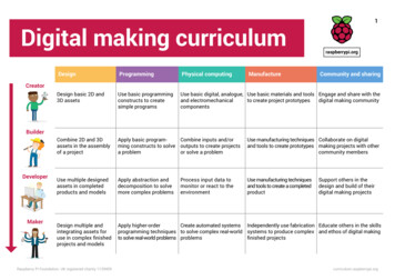
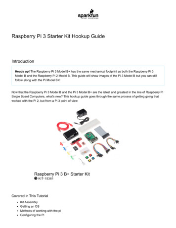
matrix display, however the wiring is the same for any backpack): Connect display (power) to Raspberry Pi 3.3V or 5V power (red wire). 5V isbrighter but if you have other devices on the I2C bus its better to go with 3.3V Connect display - (ground) to Raspberry Pi ground (black wire). Connect display D (data/SDA) to Raspberry Pi SDA (orange wire). Connect display C (clock/SCL) to Raspberry Pi SCL (purple wire). If there's a Vi2c or IO pin, connect that to 3.3V as wellBeagleBone BlackWire up the LED backpack display to the BeagleBone Black as follows (note theimage below shows a matrix display, however the wiring is the same for anybackpack): Adafruit IndustriesPage 4 of 13
Connect display (power) to BeagleBone Black 3.3V or 5V power (red wire). 5Vis brighter but if you have other devices on the I2C bus its better to go with 3.3V Connect display - (ground) to BeagleBone Black ground (black wire). Connect display D (data/SDA) to BeagleBone Black I2C2 SDA pin P9 20(orange wire). Connect display C (clock/SCL) to BeagleBone Black I2C2 SCL pin P9 19 (purplewire). If there's a Vi2c or IO pin, connect that to 3.3V as wellNote that the BeagleBone Black has two I2C interfaces and this wiring will use the/dev/i2c-1 interface. Make sure there aren't any device tree overlays loaded (https://adafru.it/dp6) which use these I2C pins for other purposes. The default BeagleBoneBlack device tree configuration with no overlays loaded will expose the necessary I2Cinterface for the wiring above.UsageInstallationBefore installing the LED backpack Python library you must first install a fewdependencies. Make sure your Raspberry Pi or BeagleBone Black has internetaccess, then connect to its command prompt and execute: Adafruit IndustriesPage 5 of 13
sudo apt-get updatesudo apt-get install build-essential python-dev python-smbus python-imaging gitNext download the LED backpack Python library code and examples (https://adafru.it/dEL) by executing:git clone https://github.com/adafruit/Adafruit Python LED Backpack.gitcd Adafruit Python LED Backpacksudo python setup.py installAfter executing the commands above the LED backpack Python library will beinstalled and available for any Python script to use.UsageYou can find a few examples of the library's usage inside the examples subdirectory.Navigate into this directory and run the appropriate script for your display. Forexample if you have your device wired to an 8x8 matrix, you would execute:cd examplessudo python matrix8x8 test.pyOnce running, you should see different pixels of the matrix light up as the displaycycles through lighting all the pixels individually. Then the example should end bydisplaying a graphic of a square with an X in the middle on the display.I'll walk through the matrix8x8 test.py code below to describe the important usagedetails of the LED backpack library:import timeimport Imageimport ImageDrawfrom Adafruit LED Backpack import Matrix8x8The first line imports the standard Python time library which is needed for the sleepfunction used later in the script. The next lines import the Python Imaging Library (https://adafru.it/dvB) which is used for drawing shapes on the display.The final line imports the Matrix8x8 module from the Adafruit LED Backpackpackage. This line is important because it tells Python that the script will need to usethe LED backpack library.# Create display instance on default I2C address (0x70) and bus number.display Matrix8x8.Matrix8x8() Adafruit IndustriesPage 6 of 13
# Alternatively, create a display with a specific I2C address and/or bus.# display Matrix8x8.Matrix8x8(address 0x74, busnum 1)# Initialize the display. Must be called once before using the display.display.begin()The next lines create an instance of the Matrix8x8 class and initialize it by calling thebegin() method. You must call begin() once before calling other functions to updatethe display!Below the first line is a commented line which shows how to create a Matrix8x8 classthat uses a different I2C address or bus number. If you're using multiple displays onthe same I2C bus they all must have a unique I2C address. By soldering jumpers onthe back of a backpack display closed (https://adafru.it/dEP) you can control theaddress associated with a display. This commented line shows how to pass anaddress parameter which overrides the default 0x70 address with a new value of0x74.If you need to use a different I2C bus, for example on a BeagleBone Black which hasmultiple I2C buses, you can pass the desired bus number in the busnum parameter. Ifyou don't provide this busnum parameter the library will try to determine the defaultI2C bus for your device--if you followed the wiring in this guide you should be all setand not need to provide the I2C bus number.# Run through each pixel individually and turn it on.for x in range(8):for y in range(8):# Clear the display buffer.display.clear()# Set pixel at position i, j to on. To turn off a pixel set# the last parameter to 0.display.set pixel(x, y, 1)# Write the display buffer to the hardware. This must be called to# update the actual display LEDs.display.write display()# Delay for half a second.time.sleep(0.5)The next part of the program will iterate through all 8 rows and columns of the displayand light up each pixel individually. You can see the clear() function is first used to turnoff all the LEDs in the display buffer. Then the set pixel() function is called and giventhe x, y coordinates of the pixel and a value of 1 to enable the pixel. Finally the writedisplay() function is called to write the display buffer to the hardware. It's veryimportant to remember to call write display() or else you won't see the display LEDschange!# Draw some shapes using the Python Imaging Library.# Clear the display buffer.display.clear() Adafruit IndustriesPage 7 of 13
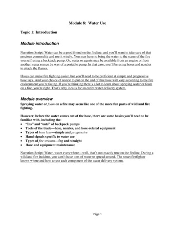
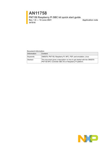
# First create an 8x8 1 bit color image.image Image.new('1', (8, 8))# Then create a draw instance.draw ImageDraw.Draw(image)# Draw a rectangle with colored outlinedraw.rectangle((0,0,7,7), outline 255, fill 0)# Draw an X with two lines.draw.line((1,1,6,6), fill 255)draw.line((1,6,6,1), fill 255)# Draw the image on the display buffer.display.set image(image)# Draw the buffer to the display hardware.display.write display()The final part of the program uses the Python Imaging Library (https://adafru.it/dvB) todraw shapes on the display. First the display buffer is cleared, and then an 8x8 pixel 1bit color image is created. Once the image is created a drawing class (https://adafru.it/dfH) is created which allows drawing on the image buffer. You can see how therectangle and line functions draw basic shapes on the image. Finally the set image()function is called to write the image to the display buffer, and the display buffer iswritten to the hardware with write display().If you'd like to draw text on the display, check out the SSD1306 library examples (https://adafru.it/dEQ) for a sample of drawing text with the PIL library. However the 8x8display is small and can't display more than a character or two!Above you can see an example of graphics drawn on the 8x8 matrix display.To use other displays such as the bicolor matrix, bicolor bar graph, 7 segment, or 14segment display the basic usage is very similar to the Matrix8x8 class above. You Adafruit IndustriesPage 8 of 13
must first import the associated module from the Adafruit LED Backpack package,create an instance of the class (optionally passing a different I2C address or busnumber), and call the begin() function to initialize the display.Beyond the setup, each display class has slightly different functionality which I'll coverbelow.Bicolor Matrix 8x8The bicolor matrix display is demonstrated in the bicolor matrix8x8 test.py script inthe examples folder. This code demonstrates using the BicolorMatrix8x8 class in avery similar way to the Matrix8x8 class above. The key difference is that the set pixel() function takes a color value instead of a 1 or 0 value like with the Matrix8x8 class.For example to set the pixel at position 1,1 red, the pixel at position 1,2 green, and thepixel at position 1,3 yellow you could write:display.set pixel(1, 1, BicolorMatrix8x8.RED)display.set pixel(1, 2, BicolorMatrix8x8.GREEN)display.set pixel(1, 3, BicolorMatrix8x8.YELLOW)Notice that each color is represented by a global value in the BicolorMatrix8x8module. You can also pass a value of 0 to turn off a specific LED.Also the Python Imaging Library is slightly different than with the single color display.Instead of creating a 1-bit color image a full RGB color image is created. Any pixel inthe image that is red (i.e. red component is 255 and all other components are 0) willhave a red LED, and likewise for green (green component is 255) or yellow (red andgreen components are 255). Any other color pixel will be treated as no color/LED lit.Below you can see an example of graphics on the bicolor 8x8 matrix: Adafruit IndustriesPage 9 of 13
Bicolor Bar Graph 24The bicolor bar graph display is demonstrated in the bicolor bargraph24 test.py script in the examples folder. This code will light up 3 bars at a time with different colorsand move them up the display. In addition to animating the bars, the example will alsocycle through the 16 different brightness levels that can be set for any of the LEDbackpack displays.The main loop of the example looks like:# Run through all bars and colors at different brightness levels.print 'Press Ctrl-C to quit.'brightness 15while True:# Set display brightness (15 is max, 0 is min).display.set brightness(brightness)for i in range(24):# Clear the display buffer.display.clear()# Light up 3 bars, each a different color and position.display.set bar(i,BicolorBargraph24.RED)display.set bar(i 1, BicolorBargraph24.GREEN)display.set bar(i 2, BicolorBargraph24.YELLOW)# Write the display buffer to the hardware. This must be called to# update the actual display LEDs.display.write display()# Delay for half a second.time.sleep(0.5)# Decrease brightness, wrapping back to 15 if necessary.brightness - 1if brightness 0:brightness 15You can see the code starts at brightness level 15, the maximum brightness level, bycalling the set brightness() function. With each iteration of the animation the code willdecrease the brightness by one level, until it reaches 0 (minimum brightness) andwraps back up to max brightness. Adafruit IndustriesPage 10 of 13
It's important to note all of the LED backpack classes support the set brightness()function! You can dim all the pixels in a matrix, bargraph, or segment display.You can also see the BicolorBargraph24 class has a set bar() function which turns ona bar at the specified position (0 to 23) with the given color. Just like with the BicolorMatrix8x8 class you specify the color from a global value in the module.7 SegmentThe 7 segment numeric display is demonstrated in the sevensegment test.py script inthe examples folder. If you run this example it will loop through displaying differentnumeric values with different precision and justification (left or right side of thedisplay). The example will also show printing hexadecimal values in a simple counter.The important functions with the 7 segment display are the print float() and print hex() functions. The print float() function will attempt to print a numeric value (eitherinteger or floating point/fractional) to the 4 character 7 segment display. Your valuemust be small enough to fit on the display, or else you'll see an error display of 4dashes, ----. For negative values a negative sign will be printed, but remember it takesup an entire digit to display!With the print float() function you can control how many decimal digits are printed fora floating point/fractional value. By default 2 decimal digits will be displayed, howeveryou can specify the decimal digits parameter with a different number of digits(including 0 for no decimal digits!). The printed value will be rounded to the desiredprecision and printed on the display.In addition to controlling the decimal digit precision, you can also change thejustification of the number on the display. By default numbers are printed with rightjustification, which means they are closest to the right side of the display. However ifyou pass the justify right False parameter to the function then the number will bedisplayed closest to the left side of the display.The print hex() function will take an integer value between 0 and FFFF and display itin hexadecimal. This is useful for displaying a large range of values like a counter,however it's less intuitive to read (unless you're a machine that understandshexadecimal!). The print hex() function also has an optional justify right booleanparameter which controls which side of the display to print the value towards.Below you can see an example of the 7 segment display showing the number -3.14: Adafruit IndustriesPage 11 of 13
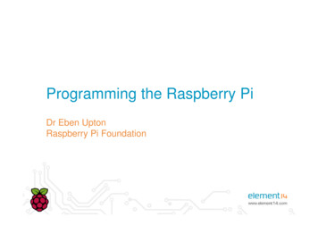
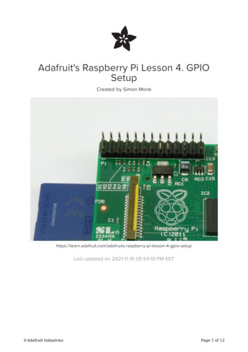
14 Segment Alphanumeric DisplayThe 14 segment alphanumeric display is demonstrated in the alphanum4 test.pyscript in the examples folder. If you run this example it will scroll a text messageacross the display. This display is great for showing complete text messages becausethe 14 segment displays are very flexible.With the 14 segment display the usage is very similar to the 7 segment display above.Just like the 7 segment display you can use the print float() and print hex() functionsto print numeric and hexadecimal values. However in addition to those functions youcan also use the print str() function to print any 4 character printable ASCII string!For example to print 'ADA!' (without quotes) to the display you could call:display.print str('ADA!')Using the 14-segment display is as easy as that, just call print str() with 4 charactersof text! Note that only the ASCII values 32-127 (the printable ASCII character range)are supported by the library right now. Adafruit IndustriesPage 12 of 13
Above you can see the 14-segment display with the text 'ADA!' written to it.Enjoy using your LED backpack displays with the Python library! If you find issues orwould like to contribute to the code, feel free to do so on the library's GitHub home (https://adafru.it/dEL). Adafruit IndustriesPage 13 of 13
Connect display D (data/SDA) to BeagleBone Black I2C2_SDA pin P9_20 (orange wire). Connect display C (clock/SCL) to BeagleBone Black I2C2_SCL pin P9_19 (purple wire). If there's a Vi2c or IO pin, connect that to 3.3V as well Note that the BeagleBone Black has two I2C interfaces and this wiring will use the/ dev/i2c-1 interface.