Transcription
Installation Instructions1747-SDN DeviceNet Scanner ModuleCatalog Number 1747-SDN, Series DTopicPageImportant User Information2Safety Guidelines2About the 1747-SDN, Series D DeviceNet Scanner Module4Before You Begin7Install DeviceNet Scanner Module9Interpret the LED Indicators12Numeric Codes and Descriptions14Specifications16Additional Resources18Publication 1747-IN058F-EN-P - December 2010
21747-SDN DeviceNet Scanner ModuleImportant User InformationSolid state equipment has operational characteristics differing from those of electromechanical equipment.Safety Guidelines for the Application, Installation and Maintenance of Solid State Controls (PublicationSGI-1.1 available from your local Rockwell Automation sales office or online athttp://literature.rockwellautomation.com) describes some important differences between solid stateequipment and hard-wired electromechanical devices. Because of this difference, and also because of thewide variety of uses for solid state equipment, all persons responsible for applying this equipment mustsatisfy themselves that each intended application of this equipment is acceptable.In no event will Rockwell Automation, Inc. be responsible or liable for indirect or consequential damagesresulting from the use or application of this equipment.The examples and diagrams in this manual are included solely for illustrative purposes. Because of the manyvariables and requirements associated with any particular installation, Rockwell Automation, Inc. cannotassume responsibility or liability for actual use based on the examples and diagrams.No patent liability is assumed by Rockwell Automation, Inc. with respect to use of information, circuits,equipment, or software described in this manual.Reproduction of the contents of this manual, in whole or in part, without written permission of RockwellAutomation, Inc., is prohibited.Throughout this manual, when necessary, we use notes to make you aware of safety considerations.WARNINGIMPORTANTATTENTIONIdentifies information about practices or circumstances that can cause an explosion ina hazardous environment, which may lead to personal injury or death, propertydamage, or economic loss.Identifies information that is critical for successful application and understanding ofthe product.Identifies information about practices or circumstances that can lead to personal injuryor death, property damage, or economic loss. Attentions help you to identify a hazard,avoid a hazard, and recognize the consequences.SHOCK HAZARDLabels may be on or inside the equipment, for example, a drive or motor, to alertpeople that dangerous voltage may be present.BURN HAZARDLabels may be on or inside the equipment, for example, a drive or motor, to alertpeople that surfaces may reach dangerous temperatures.Safety GuidelinesPublication 1747-IN058F-EN-P - December 2010
1747-SDN DeviceNet Scanner Module3Follow these guidelines for environment and enclosure information for this equipment.ATTENTIONThis equipment is intended for use in a Pollution Degree 2 industrialenvironment, in overvoltage Category II applications (as defined in IECpublication 60664-1), at altitudes up to 2000 m (6562 ft) without derating.This equipment is considered Group 1, Class A industrial equipment accordingto IEC/CISPR Publication 11. Without appropriate precautions, there may bepotential difficulties ensuring electromagnetic compatibility in otherenvironments due to conducted as well as radiated disturbance.This equipment is supplied as open type equipment. It must be mounted withinan enclosure that is suitably designed for those specific environmentalconditions that will be present and appropriately designed to prevent personalinjury resulting from accessibility to live parts. The enclosure must havesuitable flame-retardant properties to prevent or minimize the spread of flame,complying with a flame spread rating of 5VA, V2, V1, V0 (or equivalent) ifnon-metallic. The interior of the enclosure must be accessible only by the useof a tool. Subsequent sections of this publication may contain additionalinformation regarding specific enclosure type ratings that are required tocomply with certain product safety certifications.In addition to this publication, see: Industrial Automation Wiring and Grounding Guidelines, RockwellAutomation publication 1770-4.1, for additional installation requirements. NEMA Standard 250 and IEC 60529, as applicable, for explanations of thedegrees of protection provided by different types of enclosure.Follow these guidelines when you handle this equipment.ATTENTIONThis equipment is sensitive to electrostatic discharge that can cause internaldamage and affect normal operation. Follow these guidelines when you handlethis equipment. Touch a grounded object to discharge potential static.Wear an approved grounding wrist strap.Do not touch connectors or pins on component boards.Do not touch circuit components inside the equipment.Use a static-safe workstation if available.Store the equipment in appropriate static-safe packaging when not in use.Publication 1747-IN058F-EN-P - December 2010
41747-SDN DeviceNet Scanner ModuleATTENTIONTo comply with UL restrictions, this equipment must be powered from a sourcecompliant with the following:Class 2 or Limited Voltage/Current.About the 1747-SDN, Series D DeviceNet Scanner ModuleThe 1747-SDN, Series D module includes these firmware enhancements. ADR user memory space increased from 64K to 256K Support added for Online Scanlist Changes in Run Mode. This feature allows scanlistchanges to be downloaded to the scanner when the both the SLC processor and thescanner are in RUN mode. Scanner CCV attribute supported, provides optimization for RSNetWorx.Refer to the SLC 500 DeviceNet Scanner Module User Manual, publication1747-UM655, for additional information on these new enhancements.The 1747-SDN Series D module includes all features provided in the Series C module. Themodule has the following software and hardware features.Software FeaturesThe module has these software features.Slave ModeSlave mode allows processor-to-processor communication and enables the scanner toperform as a slave device to another master on the network.When the scanner module is in slave mode, it exchanges data with only one master. Youcontrol what information is exchanged through scan list configuration and associatedmapping functions of RSNetWorx for DeviceNet software.Publication 1747-IN058F-EN-P - December 2010
1747-SDN DeviceNet Scanner Module5This feature has the following variations.Module ModeDescriptionNullContains an empty or disabled scan list (default)MasterServes as a master to one or more slaves but is not simultaneously serving as a slave toanother masterSlaveServes as a slave to another masterDualServes as both a master to one or more slaves and as a slave to another mastersimultaneouslyPollA poll message is a point-to-point transfer of data (0 255 bytes) sent by the scanner modulethat solicits a response from a single device. The device responds with its input data(0 255 bytes).StrobeA strobe message is a multicast transfer of data (64 bits in length) sent by the scanner modulethat solicits a response from each strobed slave device. There is one bit for each of thepossible 64 node addresses. The devices respond with their data, which can be as much as8 bytes.Change of StateChange of state enables the scanner module to perform a scan: whenever a network data change occurs. at a user-configurable heartbeat rate.Because data is only sent on an as-needed basis, this feature increases system performance byreducing network traffic.Cyclic I/OCyclic I/O allows you to instruct the scanner module to perform a scan at a specific send rate.Because data is only sent at a periodic rate, this feature increases system performance byreducing network traffic.Publication 1747-IN058F-EN-P - December 2010
61747-SDN DeviceNet Scanner ModulePass-throughThe SLC 500 pass-through feature allows communication with the DeviceNet network fromanother network. This feature can be used to adjust and fine tune the nodes on your network.The pass-through feature is not intended to replace a 1770-KFD, 1784-PCD, 1784-PCID, or1784-PCIDS connection to the network.To use the pass-through feature you must meet the following hardware, software andfirmware requirements.Pass-through RequirementsSLC 500 Processor1747-SDN FirmwareRSLinx SoftwareM0 and M1 FilesSLC 5/03 or later4.015 5.0012.10 or laterConfigured for 361 wordsSLC 5/03 or later6.001 or later2.31 or laterConfigured for 395 wordsU2DN moduleThe pass-through feature is not intended to replace a 1784-U2DN, 1770-KFD, 1784-PCD,1784-PCID, or 1784-PCIDS connection to the network.Publication 1747-IN058F-EN-P - December 2010
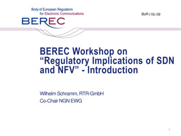
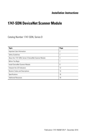
1747-SDN DeviceNet Scanner Module7Hardware FeaturesUse this illustration to identify the external features of the scanner module.DeviceNetModule Status indicatorindicates module statusNode address and statusdisplays numeric codesand indicates scannernode address or errorSTATUSMODULE NETNetwork Status indicator indicates statusof DeviceNet channel communication linkADDRESS/ERRORAccess doorWiring color codes10-pin linear plug insertedinto DeviceNet portBefore You BeginBefore you install your module you need the following items. Personal computer with Microsoft Windows 2000 or later operating systemRSNetWorx for DeviceNet software, version 2.22 or laterRSLogix 500 softwareSLC 1746 chassis with SLC 5/02, SLC 5/03, SLC 5/04, or SLC 5/05 processorPublication 1747-IN058F-EN-P - December 2010
81747-SDN DeviceNet Scanner ModuleFor network communication, you have three options. Use the pass-through feature to communicate with the DeviceNet network fromanother network. This method is intended for fine tuning and adjustment of networkdevices. Use a 1770-KFD RS-232 DeviceNet adapter or 1784-PCD, 1784-PCID, or1784-PCIDS DeviceNet PC card. This method is necessary for a complete networkconfiguration and real time monitoring of your network devices. Use a 1784-U2DN USB adapter, a 1770-KFD RS-232 DeviceNet adapter or1784-PCD, 1784-PCID, or 1784-PCIDS DeviceNet PC card. This method isnecessary for a complete network configuration and real time monitoring of yournetwork devices.Before you install your module you must know how to: program and operate an Allen-Bradley SLC 500 programmable controller. install and configure the devices on your DeviceNet network.Electronic Data Sheet RequirementThis release of the scanner module requires the latest EDS file for RSLinx Classic andRSNetWorx for DeviceNet software. If the software displays the device as anUnrecognized Device, the EDS file must be installed.You can download the latest EDS file online at:http://www.ab.com/networks/edsFor FRN 8.002 and later, you can upload the embedded EDS file from the scanner moduleitself.1. Open RSLinx Classic or RSNetWorx for DeviceNet software and right click on theUnrecognized Device.2. Select Upload EDS file from device for RSLinx Classic software or RegisterDevice for RSNetWorx for DeviceNet software.3. Follow the instructions in the EDS wizard to complete the installation.Perform a ControlFLASH UpdateIf you want to upgrade the scanner module to a newer firmware release, you must perform aControlFLASH update. To get the kit, contact Rockwell Automation Technical Support atPublication 1747-IN058F-EN-P - December 2010
1747-SDN DeviceNet Scanner Module9440.646.5800. To install the kit, refer to the ControlFLASH Firmware Upgrade Kit UserManual, publication 1756-QS105.IMPORTANTYou can update Series A and B scanner modules up to FRN 7.006. Series Cscanner modules support only FRN 8.001 to 8.006. Series D scanner modulessupport FRN 9.001 and later.Confirm Processor and Adapter CompatibilityMake sure that your processor and adapter are compatible. You can use the 1747-SDNscanner module in any slot in an I/O chassis except for the leftmost, which is reserved for theSLC 500 processor.IMPORTANTYou cannot use the scanner module in a remote I/O chassis with a 1747-ASBadapter module. The adapter module does not support M-file transfer.Install DeviceNet Scanner ModuleFollow these steps to install the module.1. Turn off the chassis power supply.WARNINGIf you insert or remove the module while backplane power is on, an electricalarc can occur. This could cause an explosion in hazardous location installations.Be sure that power is removed or the area is nonhazardous before proceeding.2. Select a slot for the module in the chassis.You may use any slot except the leftmost slot, which is reserved for the SLC 500processor.Publication 1747-IN058F-EN-P - December 2010
101747-SDN DeviceNet Scanner Module3. Insert the module into the slot you have selected.4. Apply firm, even pressure to seat the module in the I/O chassis backplaneconnectors.Connect the Module to the DeviceNet NetworkATTENTIONTo comply with the CE Low Voltage Directive (LVD), DeviceNet must bepowered from a source compliant with the following: Safety Extra Low Voltage (SELV) Protected Extra Low Voltage (PELV).To comply with UL restrictions, DeviceNet must be powered from a sourcecompliant with the following: Class 2 Limited Voltage/Current.Follow these steps to connect the module to the DeviceNet network.1. Turn off the network power supply.Publication 1747-IN058F-EN-P - December 2010
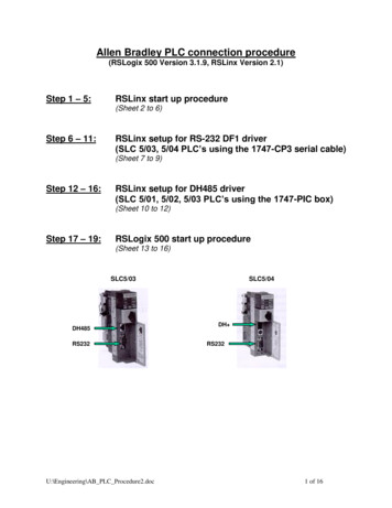
1747-SDN DeviceNet Scanner ModuleWARNING11If you connect or disconnect the communications cable with power applied tothis module or any device on the network, an electrical arc can occur. This couldcause an explosion in hazardous location installations.2. Connect the DeviceNet drop line to the 10-pin linear plug by matching the wireinsulation colors to the colors shown on the label. 24V RedCan H WhiteDrain/ShieldCan L Blue 24V Return Black10-pin linearplugRedWhiteShieldBlueBlackFront of Module3. Locate the DeviceNet port connector on the front of the module.4. Insert the 10-pin linear plug into the DeviceNet port connector.10-pin Linear plugDeviceNet portconnectorDeviceNet drop lineYou have installed and wired your module. To operate the module you must apply power andthen configure and program the SLC processor to communicate with it.Publication 1747-IN058F-EN-P - December 2010
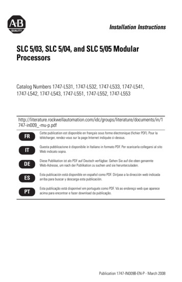
121747-SDN DeviceNet Scanner ModuleApply Chassis PowerWhen you apply chassis power, the module numeric indicators cycle through the followingdisplays.DeviceNetSTATUSMODULE NETModuleNumericIndicatorsADDRESS/ERROR Seven-segment lamp test (88)Firmware major revision (01 7F hexadecimal)Firmware minor revision (01 FF hexadecimal)Communication rate (indicates 00 for the default of 125, 01 for 250, or 02 for500 Kbps) Node address (00 63 with 63 as the default)Use the RSNetWorx for DeviceNet software to change the communication rate and nodeaddress.Refer to the Numeric Code Display Summary table on page 14 for a complete listing ofnumeric displays.Interpret the LED IndicatorsThe bicolor (green/red) module status indicator (MODULE) on the front of your moduledisplays module status. It indicates whether the module has power and is functioningproperly.Module Status LED IndicatorIndicator ColorDescriptionCorrective ActionOffThere is no power applied to themodule.Verify power connections and applypower.GreenThe module is operating normally.No action required.Flashing GreenThe module is not configured.Configure the module.Flashing RedThere is an invalid configuration.Check configuration setup.RedThe module has an unrecoverablefault.Replace the module.Publication 1747-IN058F-EN-P - December 2010
1747-SDN DeviceNet Scanner Module13The DeviceNet channel has a bicolor (green/red) network status indicator (NET). Thefollowing table provides troubleshooting information about the DeviceNet channelcommunication link.DeviceNet Channel CommunicationIndicatorColorDescriptionDevice OperationCorrective ActionOffThe channel is disabled forDeviceNet communication.The device has no power orthe channel is disabled forcommunication due to bus offcondition, loss of networkpower, or has beenintentionally disabled.Power-up the module, providenetwork power to the channel,and be sure the channel isenabled in both the moduleconfiguration table and themodule command word.GreenAll slave devices in the scanlist table are communicatingnormally with the module.Normal operation.None.FlashingGreenThe channel is enabled butno communication isoccurring.The two-digit numeric displayfor the channel indicates anerror code that provides moreinformation about thecondition of the channel.Configure the scan list tablefor the channel to add devices.FlashingRedAt least one of the slavedevices in the module’s scanlist table has failed tocommunicate with themodule.The two-digit numeric displayfor the channel displays anerror code that provides moreinformation about thecondition of the channel.Examine the failed device andthe scan list table for accuracy.RedThe module may bedefective.The communications channelhas failed. The two-digitnumeric display for thechannel displays an error codethat provides more informationabout the condition of thechannel.Reset module. If failurespersist, replace module.Publication 1747-IN058F-EN-P - December 2010
141747-SDN DeviceNet Scanner ModuleNumeric Codes and DescriptionsYour module uses numeric displays to indicate diagnostic information about the status ofyour module. The display flashes at 1-second intervals. The following table summarizes themeanings of the numeric codes.NumericCodeDescriptionCorrective Action0 63Normal operation. The numeric displayindicates the 1747-SDN node address on theDeviceNet network.None.70Module failed Duplicate Node Address check.Change the module channel address to anotheravailable one. The node address you selectedis already in use on that channel.71Illegal data in scan list table (node numberalternately flashes).Reconfigure the scan list table and remove anyillegal data.72Slave device stopped communicating (nodenumber alternately flashes).Inspect the field devices and verifyconnections.73Identity information for the device does notmatch electronic key in scan list table entry.Verify that the correct device is at this nodenumber. Make sure that the device at thescrolling node address matches the desiredelectronic key (vendor, product code, producttype).74Data overrun on port detected.Modify your configuration and check for invaliddata. Check network communication traffic.75No traffic from other modules detected on thenetwork.Check the network configuration. Scanlist maybe empty.76No direct network traffic for module detected.None. The module detects other networkcommunication.77Data size expected by the device does notmatch scan list entry.Reconfigure your module for the correcttransmit and receive data sizes.78Slave device in scan list table does not exist.Add the device to the network, or delete thescan list entry for that device.79Module has failed to transmit a message.Make sure that your module is connected to avalid network.Check for disconnected cables.80Module is in Idle mode.Put controller in Run mode. Enable Run bit inmodule command register.81Module is in Fault mode.Check Module Command Register for fault bitset.Publication 1747-IN058F-EN-P - December 2010
1747-SDN DeviceNet Scanner Module15NumericCodeDescriptionCorrective Action82Error detected in sequence of fragmented I/Omessages from device.Check scan list table entry for slave device tomake sure that input and output data lengthsare correct. Check slave device configuration.83Slave device is returning error responses whenmodule attempts to communicate with it.Check accuracy of scan list table entry. Checkslave device configuration. Slave device maybe in another master’s scan list. Reboot slavedevice.84Module is initializing the DeviceNet network.None. This code clears itself once moduleattempts to initialize all slave devices on thenetwork.85Data size was incorrect for this device atruntime.Slave device is transmitting incorrect lengthdata.Verify device is not configured for variable pollconnection size.Try replacing the device.86Device is producing zero length data (idlestate) while module is in Run mode.Check device configuration and slave nodestatus.87The primary owner has not allocated the slave.Put the primary owner online.88The connection choices (polled, strobed)between the primary connection and theshared input only connection do not match.Reconfigure the shared input-only connectionchoices to be the same as, or a subset of, thechoices for the primary connection.89Slave device initialization using Auto DeviceReplacement parameters failed.Put the slave device into configurable mode.If the slave is configured offline, check its EDSfile.Check to see if the slave device has beenreplaced with an incompatible device.90User has disabled communication port.Check Module Command Register for DISABLEbit set.91Bus-off condition detected on comm port.Module is detecting communication errors.Check DeviceNet connections and physicalmedia integrity. Check system for failed slavedevices or other possible sources of networkinterference.92No network power detected on communicationport.Provide network power. Make sure thatmodule drop cable is providing network powerto module comm port.95Application FLASH update in progress.None. Do not disconnect the module whileapplication FLASH is in progress. You will loseexisting data in the module memory.97Module operation halted by user command.Check Module Command Register for HALT bitset.Publication 1747-IN058F-EN-P - December 2010
161747-SDN DeviceNet Scanner ModuleNumericCodeDescriptionCorrective Action98Unrecoverable firmware failure.Service or replace your module.99Unrecoverable hardware failure.Service or replace your module.E2RAM Test FailureService or replace your module.E4Lost power during FLASH upgradeService or replace your module.E5No application codeService or replace your module.E9Module memory has been flushed for factorydefault settings.Cycle module power to recover.SpecificationsSLC DeviceNet Scanner — 1747-SDNAttributeValueModule locationSLC 5/02 or later chassisModule defaultsNode Address – 63Baud Rate – 125 KbpsPower consumption- Backplane current- DeviceNet5V DC, 500 mA24V DC, 90 mA Class 2Isolation voltage30V (continuous), Basic Insulation TypeTested at 500V AC for 60 s, DeviceNet to backplaneTemperature, operatingIEC 60068-2-1 (Test Ad, Operating Cold),IEC 60068-2-2 (Test Bd, Operating Dry Heat),IEC 60068-2-14 (Test Nb, Operating Thermal Shock):0 60 oC (32 140 oF)Temperature, non-operatingIEC 60068-2-1 (Test Ab, Unpackaged Nonoperating Cold),IEC 60068-2-2 (Test Bc, Unpackaged Nonoperating Dry Heat),IEC 60068-2-14 (Test Na, Unpackaged Nonoperating Thermal Shock):-40 85 oC (-40 185 oF)Relative humidityIEC 60068-2-30 (Test Db, Unpackaged Damp Heat):5 95% non-condensingVibrationIEC60068-2-6 (Test Fc, Operating):2 g @10 500 HzShockIEC60068-2-27:1987, Test Ea (Unpackaged shock, ES#002)Operating — 30 gNon-operating — 50 gPublication 1747-IN058F-EN-P - December 2010
1747-SDN DeviceNet Scanner Module17SLC DeviceNet Scanner — 1747-SDNAttributeValueEmissionsCISPR 11:Group 1, Class A (with appropriate enclosure)ESD immunityIEC 61000-4-2:6 kV contact discharges8 kV air dischargesRadiated RF immunityIEC 61000-4-3:10 V/m with 1 kHz sine-wave 80% AM from 80 2000 MhzEFT/B immunityIEC 61000-4-4: 2 kV at 5 kHz on communication portsSurge transient immunityIEC 61000-4-5: 2 kV line-earth(CM) on communications portsConducted RF immunityIEC 61000-4-6:10 Vrms with 1 kHz sine-wave 80% AM from 150 kHz 80 MHzMagnetic field immunityIEC 61000-4-830A/m long duration at 50 HzEnclosure type ratingNone (open style)Wiring- Size- Category(1)Refer to DeviceNet Media Design Installation Guide, publicationDNET-UM0722 — on communication ports10-pin Linear plug- Torque- Catalog number0.6 0.8 Nm (5 7 lb-in)1787-PLUG10RNorth American temperature codeT5(1)Use this Conductor Category information for planning conductor routing. Refer to Industrial Automation Wiring andGrounding Guidelines, publication 1770-4.1.Publication 1747-IN058F-EN-P - December 2010
181747-SDN DeviceNet Scanner ModuleCertifications - 1747-SDNCertification (when product isValuemarked)(1)c-UL-usUL Listed Industrial Control Equipment, certified for US and Canada. SeeUL File E113724.UL Listed for Class I, Division 2 Group A, B, C, D Hazardous Locations,certified for US and Canada. See UL File E10314.CEEuropean Union 89/336/EEC EMC Directive, compliant with:EN 61000-6-2; Industrial ImmunityEN 61000-6-4; Industrial EmissionsC-TickAustralian Radiocommunications Act, compliant with:AS/NZS CISPR 11; Industrial EmissionsODVAODVA conformance tested to ODVA DeviceNet specifications(1)See the Product Certification link at http://www.ab.com for Declaration of Conformity, Certificates, and other certificationdetails.Additional ResourcesResourceDescriptionSLC 500 DeviceNet Scanner Module User Manual, publication1747-UM655Provides application examples for theDeviceNet scanner module.ControlFlash Firmware Upgrade Kit User Manual, publication1756-QS105Provides instructions on using ControlFlashto upgrade the firmware.Getting Results with RSLogix 500, publication LG500-GR002Provides information on RSLogix 500software.Getting Results with RSLinx, publication LINX-GR001Provides information on RSLinx software.DeviceNet Media Design and Installation Guide, DNET-UM072Provides information on using DeviceNetcommunication network.Getting Results with RSNetWorx for DeviceNet, publicationDNET-GR001Provides information on using RSNetWorxfor DeviceNet software.You can view or download publications at http://literature.rockwellautomation.com. Toorder paper copies of technical documentation, contact your local Rockwell Automationdistributor or sales representative.Publication 1747-IN058F-EN-P - December 2010
1747-SDN DeviceNet Scanner Module19North American Hazardous Location ApprovalThe following information applies whenoperating this equipment in hazardouslocations:Informations sur l’utilisation de cetéquipement en environnementsdangereux:Products marked "CL I, DIV 2, GP A, B, C, D" aresuitable for use in Class I Division 2 Groups A, B, C,D, Hazardous Locations and nonhazardous locationsonly. Each product is supplied with markings on therating nameplate indicating the hazardous locationtemperature code. When combining products withina system, the most adverse temperature code(lowest "T" number) may be used to help determinethe overall temperature code of the system.Combinations of equipment in your system aresubject to investigation by the local Authority HavingJurisdiction at the time of installation.Les produits marqués "CL I, DIV 2, GP A, B, C, D" neconviennent qu'à une utilisation en environnementsde Classe I Division 2 Groupes A, B, C, D dangereux etnon dangereux. Chaque produit est livré avec desmarquages sur sa plaque d'identification qui indiquentle code de température pour les environnementsdangereux. Lorsque plusieurs produits sont combinésdans un système, le code de température le plusdéfavorable (code de température le plus faible) peutêtre utilisé pour déterminer le code de températureglobal du système. Les combinaisons d'équipementsdans le système sont sujettes à inspection par lesautorités locales qualifiées au moment del'installation.WARNINGEXPLOSION HAZARD Do not disconnect equipmentunless power has beenremoved or the area is knownto be nonhazardous. AVERTISSEMENTRISQUE D’EXPLOSION Couper le courant ou s'assurerque l'environnement est classénon dangereux avant dedébrancher l'équipement.Do not disconnect connectionsto this equipment unless powerhas been removed or the areais known to be nonhazardous.Secure any externalconnections that mate to thisequipment by using screws,sliding latches, threadedconnectors, or other meansprovided with this product. Couper le courant ou s'assurerque l'environnement est classénon dangereux avant dedébrancher les connecteurs.Fixer tous les connecteursexternes reliés à cetéquipement à l'aide de vis,loquets coulissants,connecteurs filetés ou autresmoyens fournis avec ce produit. Substitution of any componentmay impair suitability for ClassI, Division 2. If this product containsbatteries, they must only bechanged in an area known tobe nonhazardous.La substitution de toutcomposant peut rendre cetéquipement inadapté à uneutilisation en environnement deClasse I, Division 2. S'assurer que l'environnementest classé non dangereux avantde changer les piles.Publication 1747-IN058F-EN-P - December 2010
Rockwell Automation SupportRockwell Automation provides technical information on the Web to assist you in using itsproducts.At http://support.rockwellautomation.com, you can find technical manuals, a.knowledge base of FAQs, technical and application notes, sample code and links to softwareservice packs, and a MySupport feature that you can customize to make the best use of thesetools.For an additional level of technical phone support for installation, configuration andtroubleshooting, we offer TechConnect support programs. For more information, contactyour local distributor or Rockwell Automation representative, or ation AssistanceIf you experience a problem within the first 24 hours of installation, please review theinformation that's contained in this manual. You can also contact a special Customer Supportnumber for initial help in getting your product up and running.United States1.440.646.3434Monday – Friday, 8 a.m. – 5 p.m. ESTOutside United StatesPlease contact your local Rockwell Automation representative for any technicalsupport issues.New Product Satisfaction ReturnRockwell Automation tests all of its products to ensure that they are fully operational whenshipped from the manufacturing facility. However, if your product is not functioning andneeds to be returned, follow these procedures.United StatesContact your distributor. You must provide a Customer S
SLC 1746 chassis with SLC 5/02, SLC 5/03, SLC 5/04, or SLC 5/05 processorFor network communication, you have three options. Use the pass-through feature to communicate with the DeviceNet network from another network. This method is intended for fine tuning and adjustment of network devices.