Transcription
10.5”/12.1” 24V DCQUICKPANEL(QPICxDE0000/QPLCxDE0000)Installation GuideQuickPanel Installation GuideGFK-2071
The following are trademarks of Total Control Products, Inc.: QUICKPANELÔ andQUICKPANEL jr.ÔInformation in this document is subject to change without notice and does not represent a commitmenton the part of Total Control Products, Inc. The software described in this document is provided under alicense agreement. The software may be used or copied only under the terms of the agreement. Onlyone copy of the software may be made for a backup.Total Control Products, Inc. makes no warranty, either expressed or implied, including but not limitedto any implied warranties of merchantability or fitness for a particular purpose, regarding thesematerials and makes such materials available solely on an "as-is" basis.In no event shall Total Control Products, Inc. be liable to anyone for special, collateral, incidental, orconsequential damages in connection with or arising out of purchase or use of these materials. The soleand exclusive liability to Total Control Products, Inc., regardless of the form of action, shall not exceedthe purchase price of the materials described herein.No part of this manual may be reproduced or transmitted in any form or by any means, electronic ormechanical, including photocopying, recording, or information storage and retrieval systems, for anypurpose other than the purchaser's personal use, without the express written permission of TotalControl Products, Inc.Copyright 1995, Total Control Products, Inc. All rights reserved.Total Control Products, Inc.2700 Oxford Tower, 10235-101 Street, Edmonton, Alberta T5J 3G1, CANADAPhone (780) 420-2000, Fax (780) 420-2049
Essential Safety PrecautionsWARNINGSSystem Design Do not create QP touch panel switches that could possibly endanger the safety ofequipment and personnel. This is because damage to the QP, its I/O unit(s),cable(s), and other related equipment can cause an output signal to remain continuously ON or OFF and possibly cause a major accident. To prevent this type ofaccident, design monitoring circuits using devices such as limit switches, etc. todetect incorrect device movement. Also, to prevent accidents related to incorrectsignal output, or incorrect operation, design your system so that all switches used tocontrol vital machine operations are operated via a control system that is separatefrom the QP. Do not create switches used to control machine safety operations, such as anemergency stop switch, as a QP touch screen icon. Be sure to install theseswitches as separate hardware switches, otherwise severe bodily injury or equipment damage can occur. Please design your system so that equipment will not malfunction due to a communication fault between the QP and its host controller. This is to prevent any possibility of bodily injury or material damage. The QP is not appropriate for use with aircraft control devices, aerospace equipment, central trunk data transmission (communication) devices, nuclear powercontrol devices, or medical life support equipment, due to these devices’ inherentrequirements of extremely high levels of safety and reliability. When using the QP with transportation vehicles (trains, cars and ships), disasterand crime prevention devices, various types of safety equipment, non-life supportrelated medical devices, etc. redundant and/or failsafe system designs should beused to ensure the proper degree of reliability and safety. Do not use the QP unit as a warning device for critical alarms that can cause serious operator injury, machine damage or production stoppage. Critical alarm indicators and their control/activator units must be designed using stand-alone hardwareand/or mechanical interlocks. After the QP’s backlight burns out, unlike the QP’s “Standby Mode”, the touch panelis still active. If the operator fails to notice that the backlight is burned out andtouches the panel, a potentially dangerous machine miss-operation can occur.Therefore, do not use QP touch switches for the control of any equipment safetymechanisms, such as Emergency Stop switches, etc. that protect humans andequipment from injury and damage. If your QP's backlight suddenly turns OFF, usethe following steps to determine if the backlight is actually burned out.1) If your QP is not set to "Standby Mode" and the screen has gone blank, yourbacklight is burned out.2) Or, if your QP is set to Standby Mode, but touching the screen does not causethe display to reappear, your backlight is burned out.Also, to prevent accidental machine miss-operation, Digital suggests you use theQP’s built-in “USE TOUCH PANEL AFTER BACKLIGHT BURNOUT” feature, thatwill automatically detect a burnout and disable the touch screen.Installation High voltage runs through the QP. Except for replacing the backlight, never disassemble the QP, otherwise an electric shock can occur. Do not modify the QP unit. Doing so may cause a fire or an electric shock. Do not use the QP in an environment where flammable gasses are present, sinceoperating the QP may cause an explosion.Wiring To prevent an electric shock, be sure to confirm that the QP's power cord is notconnected to the main power when connecting any cords, cables or lines to the QP. Do not use power beyond the QP's specified voltage range. Doing so may cause afire or an electric shock.Maintenance The QP uses a lithium battery for backing up its internal clock data. If the battery isincorrectly replaced, the battery may explode. To prevent this, please do not replace the battery yourself. When the battery needs to be replaced, please contactyour local distributor.
CAUTIONSInstallation Be sure to securely connect all cable connectors to the QP. A loose connectionmay cause incorrect input or output.Wiring Ground the QP's FG line separately from other units’ FG lines. Putting these FGlines too close may cause an electric shock or unit malfunction. Be sure to use agrounding resistance of 100Ω or less and a 2mm2 or thicker wire, or your country’sapplicable standard. Correctly wire the QP, be sure that the rated voltage and terminal layout are withinthe designated range. If the voltage supplied differs from the rated voltage, orincorrect wiring or grounding is performed, it may cause a fire or unit malfunction. Use only the designated torque to tighten the QP's terminal block screws. If thesescrews are not tightened firmly, it may cause a short-circuit, fire, or QP malfunction. Be careful that metal filings and wiring debris do not fall inside the QP, since theycan cause a fire, QP malfunction, or incorrect operation.Maintenance The liquid crystal panel contains a powerful irritant and if for any reason the panelis damaged and this liquid contacts any part of your body, be sure to wash thatarea with running water for 15 minutes. If any of this liquid enters your eye, flushyour eye for 15 minutes with running water and contact a physician. Prior to inserting or removing a CF Card, be sure to turn the QP’s CF Card ACCESS switch OFF and to confirm that the ACCESS lamp is not lit. If you do not,CF Card internal data may be damaged or lost. While a CF Card is being accessed, NEVER turn OFF or reset the QP, or insert orremove the CF Card. Prior to performing these operations, create and use a special QP application screen that will prevent access to the CF Card.Unit Disposal When this unit is disposed of, it should be done so according to your country'sregulations for similar types of industrial waste.General Safety Precautions Do not strike the touch panel with a hard or pointed object, or press on the touchpanel with too much force, since it may damage the touch panel or the display. Do not install the QP where the ambient temperature can exceed the allowedrange. Doing so may cause the QP to malfunction or shorten its operation life. Do not restrict or limit the QP’s naturally occurring rear-face ventilation, or storing orusing the QP in an environment that is too hot. Do not use this unit in areas where large, sudden temperature changes can occur.These changes can cause condensation to form inside the unit, possibly causingthe unit to malfunction. Do not allow water, liquids, metal or charged particles to enter inside the QP’scase, since they can cause either a QP malfunction or an electrical shock. Do not use or store the QP in direct sunlight, or in excessively dusty or dirty environments. Do not store or use the unit where strong jolting or excessive vibration can occur. Do not store or use the QP where chemicals (such as organic solvents, etc.) andacids can evaporate, or where chemicals and acids are present in the air.Corrosive chemicals: Acids, alkalines, liquids containing saltFlammable chemicals: Organic Solvents Do not use paint thinner or organic solvents to clean the QP. Do not store or operate the LCD display in areas receiving direct sunlight, since thesun's UV rays may cause the LCD display’s quality to deteriorate. Storing this unit in areas at a temperature lower than is recommended in thismanual’s specifications may cause the LCD display’s liquid to congeal, which maydamage the panel. Conversely, if the storage area’s temperature becomes higherthan the allowed level, the LCD’s liquid will become isotropic, causing irreversibledamage to the LCD. Therefore, be sure to store the panel only in areas wheretemperatures are within those specified in this manual. After turning the QP OFF, be sure to wait a few seconds before turning it ONagain. If the QP started too soon, it may not start up correctly. Due to the possibility of unexpected accidents, be sure to back up the QP’s screendata regularly.
UL/c-UL(CSA) ApprovalThe QPICxDE0000 and the QPLCxDE0000 are UL/c-UL(CSA) listedproducts. (UL file No. E182139)This Unit conforms as a component to the following standards: UL508Industrial Control Equipment UL1604Electrical Equipment for Use in Class I and II Division 2 and Class III Hazardous (Classified) Locations CAN/CSA-C22.2, Nos.142, and 213-M1987Standard for Safety of Information Technology Equipment, including ElectricalBusiness EquipmentQPICxDE0000 (UL Registration Model : 2880045-01)QPLCxDE0000 (UL Registration Model : 2880045-02) Cautions The QP must be used as a built-in component of an end-use product. The QP should be installed in the front face of a metal panel. If the QP is installed so as to cool itself naturally, be sure to install it in a vertical panel. Also, be sure that the QP is mounted at least 100mm away fromadjacent structures and other equipment, otherwise, the heat generated by theQP's internal components may become higher than that allowed by UL standard requirements.UL1604 Conditions of Acceptability and Handling Cautions:1. Power, input and output (I/O) wiring must all be in accordance with Class I,Division 2 wiring methods, Article 501-4 (b) of the National Electrical Code,NFPA 70, or as specified in Section 18-152 of the Canadian Electrical Codefor units installed within Canada, and in accordance with that location's authority.2. Suitable for use in Class I, Division2, GroupsA, B, C and D hazardous location, or nonhazardous locations only.3. WARNING: Explosion hazard - substitution of components may impair suitability for Class I, Division2.4. WARNING: Explosion hazard - do not disconnect equipment unless powerhas been switched off or the area is known to be nonhazardous.5. WARNING: Explosion hazard - when in hazardous locations, turn off powerbefore replacing or wiring modules.CE MarkingQPICxDE0000 and QPLCxDE0000 are CE marked , EMC compliantproducts.These units also conform to EN55011 ClassA , EN61000-6-2 directives.For detailed CE marking information, please contact your local distributor.
Package ContentsThe following items are included in the QP's package. Before using the QP, pleaseconfirm that all items listed here are present. QP Unit (1)(QPICxDE0000/QPLCxDE0000) QuickPanel Installation Guide (1) This Guide QP InstallationGuide Installation Fasteners (4) Installation Gasket (1)This unit has been carefully packed, with special attention to quality. However,should you find anything damaged or missing, please contact your local distributor immediately.Options QuickPanelHardware ReferenceGuideTCPQP HardwareReferenceGuide Cables Software Maintenance Parts
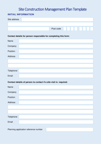
1 Part NamesA : DisplayB : Touch PanelC : Status LEDD : Power Input Terminal BlockE : Expansion Unit Interface 1F : Expansion Unit Interface 2G : CF Card Expansion InterfaceH : CF Card CoverI : CF Card Access LampJ : CF Card SlotK : Serial Interface (HOST-I/F 25-pin)L : Serial Interface (SUB-SIO 9-pin)M: Printer Interface(Half Pitch 20-pin)N : Ethernet InterfaceO : Screw Lock Terminal BlockP : Tool ConnectorConnects a Data Transfer Cableor bar code readerA,BCG EDFHIJKMNLOP2 Dimensions301[11.85]Unit:mm CxDE0000)
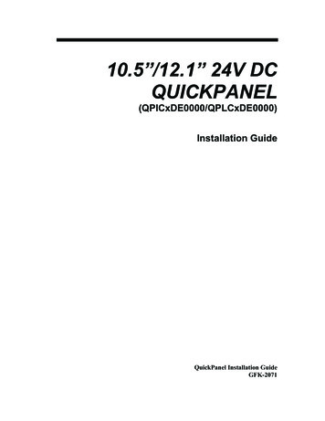
3 Dip SwitchesThese switches are located inside the CF Card's cover.Dip SwitchesRear View of QPDip Switch1234FunctionThis Dip switchsetting controlsthe startup from aCF Card.ReservedReservedThis settingcontrols the forcedclosing of the CFCard cover.ONStartup fromCF Card isenabled.OFFStartup fromCF Card isdisabled.NoteCF Card withstartup datarequired.Forced close Forced close Used when CFenabled.disabled.Card cover isdamaged.
4 Interfaces Serial Interface (HOST-I/F)This interface is used to connect the QP to the host (PLC), via an RS-232C or RS422 cable.Pin Arrangement1141325Pin RCSAERANCNCNCMeaningFrame GroundSend Data (RS-232C)Receive Data (RS-232C)Request to Send (RS-232C)Clear to Send (RS-232C)Data Set Ready (RS-232C)Signal GroundCarrier Detect (RS-232C)Termination (RS-422)Receive Data A (RS-422)Send Data A (RS-422)No Connection(Reserved)No Connection(Reserved)5V 5% Output 0.25ASend Data B (RS-422)Receive Data B (RS-422)Ring Indicate (RS-232C)Clear to Send B (RS-422)Enable Receive B (RS-422)Enable Receive (RS-232C)Clear to Send A (RS-422)Enable Receive A (RS-422)No Connection(Reserved)No Connection(Reserved)No Connection(Reserved)Recommended Connector : Dsub 25 pin plug XM2A-2501 made by OMRON Corp. Recommended Cover: Dsub 25 pin Cover XM2S-2511 made by OMRON Corp. Jack Screw XM2Z-0071 made by OMRON Corp. Recommended Cable: CO-MA-VV-SB5P x 28AWG made by HITACHI Cable Ltd. Since Pin#14(VCC) is unprotected, be sure to keep the outputcurrent within the rated range. Be sure to connect the QP's SG/GND (Signal Ground) terminalto the other (host) unit's Signal Ground terminal.Use rough metric type M2.6 x 0.45p threads to hold the cable’s set(fastening) screws in place.
When creating a cable, please be aware of the following: For RS-422 Connectors The following pairs of pin no.s must be connected (shorted).#18 (CSB) - #19 (ERB).#21 (CSA) - #22 (ERA) Connecting the #9 (TRMX) and #10 (RDA) wires, adds a terminationΩ between RDA and RDB.resistance of 100Ω Use a 4-wire cable when the PLC type is Memory Link and the cableis RS-422. For RS-232C Connectors Do not connect #9 (TRMX), #10 (RDA), #11 (SDA), #15 (SDB), #16(RDB), #18 (CSB), #19 (ERB), #21 (CSA), and #22 (ERA). Serial Interface (SUB-SIO) – Not Supported (contact factory)Connect a Serial Bar-code reader or a 2-Dimensional-code reader to this interface.Pin ArrangementPin # Signal NameMeaning1CDCarrier Detect(RS-232C)2RDReceive Data(RS-232C)3SDSend Data(RS-232C)594EREnable Receive(RS-232C)5SGSignal Ground6DRData Set Ready(RS-232C)617RSRequest to Send(RS-232C)8CSClear to Send(RS-232C)9RI/VCCRing Indicate(RS-232C) 5V 5% 0.25ARecommended Connector : Dsub 9 pin plug XM2D-0901 made by OMRON Corp. Recommended Cover: Dsub 9 pin cover XM2S-0913 made by OMRON Corp. Jack Screw XM2Z-0073 made by OMRON Corp. Since Pin#9(RI/VCC) is unprotected, be sure to keep the outputcurrent within the rated range. Printer Interface (Half Pitch 20-pin)Pin Arrangement1111020Pin #1234567891011121314151617181920Signal vedData SignalData SignalData SignalGroundSelect Condition(Input)Data SignalStrobe Signal(Output)Busy Signal(Input)Data SignalData SignalGroundPrinter Error(Input)GroundData SignalData SignalPaper EndInitialize Signal(Output)Ground
Screw Lock Terminal Block (12 pin) – Not Supported (contact factory)This interface performs external reset, remote I/O and sound output.Pin ArrangementI/FPin No. Signal NameMeaningExternal Reset1AUXCOM External Reset Common2AUXRESET External Reset InputAUX3RUNOnline14ALARM System Alarm Output5OUTCP 24VDC6BUZZExternal Buzzer Output7Reserved Reserved8OUTCN 0V9Reserved Reserved12Sound I/F10SP OUT Speaker Output11GNDGround12LINE OUT Sound Line Out Output Ethernet InterfaceThis interface complies with the IEEE802.3 standard for Ethernet (10BASE-T)connections. This interface uses an RJ-45 type modular jack connector (8 points). CF Card InterfaceThis slot accepts a CF Card. Expansion CF Card InterfaceThis interface is for connecting the Front Maintenance CF Card Unit. Expansion Unit Interface 1This interface is used to connect an expansion unit that can transmit data over aFieldbus or similar type of network. Expansion Unit Interface 2Provides expanded features.5 Installation Confirm the Installation Gasket's PositioningIt is strongly recommended that you use the gasket. It absorbs vibration in additionto repelling water.Place the QP on a level surface with the display panel facing downward. Checkthat the QP’s installation gasket is seated securely into the gasket’s groove, whichruns around the perimeter of the panel’s frame. Before installing the QP into a cabinet or panel, check that theinstallation gasket is securely attached to the unit. Be sure the gasket's seam is not inserted into any of the unit'scorners, only in the straight sections of the groove. Inserting itinto a corner may lead to its eventually tearing. A gasket which has been used for a long period of time may havescratches or dirt on it, and could have lost much of its dust anddrip resistance. Be sure to change the gasket periodically (orwhen scratches or dirt become visible).Rear faceGasket
Create a Panel Cut and insert the QP into the panel from the front3-R4Panelerd301.5 10 [11.87 0.040 ] un227.5 10[8.96 0.040 ]Unit: mm [in]QuickPanel Attach the Installation Fasteners from Inside the PanelThe following figures show the four(4) fastener insertion slot locations. Inserteach fastener's hook into the slot and tighten it with a screwdriver.Insertion SlotsTopPanelInsertion SlotsBottomInstallationfastenerQP Tightening the screws with too much force can damage the QP'splastic case. The necessary torque is 0.5 N m. Depending on the installation panel's thickness, etc., the number ofinstallation fasteners used may need to be increased to provide thedesired level of moisture resistance.6 WiringWARNINGS To avoid an electric shock, when connecting the QP's power cordterminals to the power terminal block, confirm that the QP's powersupply is completely turned OFF, via a breaker, or similar unit. The QPICxDE0000/QPLCxDE0000 units are designed to useonly DC24V input. Any other power level can damage both theQP and the power supply. Since there is no power switch on the QP unit, be sure to attach abreaker-type switch to its power cord.
When the FG terminal is connected, be sure the wire is grounded.Not grounding the QP unit will result in excess noise and vibration. Wherever possible, use thick wires (max. 2 mm2) for power terminals, and twist the wire ends before attaching the ring terminals. Be sure to use the following size ring terminals.*1 To avoid a short caused by loose ring terminals, be sure to usering terminals with an insu
manual’s specifications may cause the LCD display’s liquid to congeal, which may damage the panel. Conversely, if the storage area’s temperature becomes higher than the allowed level, the LCD’s liquid will become isotropic, causing