Transcription
INSTALLATION ANDOPERATOR’S MANUALCOAL GUN BOILERModels: S130 S260IMPORTANT: IN ORDER TO ACHIEVE SAFE AND SATISFACTORYRESULTS FROM YOUR ALTERNATE HEATING SYSTEMS BOILER, READSAFETY RULES AND INSTRUCTIONS CAREFULLY BEFOREINSTALLING AND OPERATING. ALL INSTALLATIONS MUST BE INACCORDANCE WITH STATE AND LOCAL CODES. SAVE THESEINSTRUCTIONS FOR FUTURE REFERENCE.Your Alternate Heating Systems Boiler is capable of generatingvery hot temperatures. Boiler temperatures and flames in theignition box area are capable of causing ignition or explosion ofexplosive or flammable products or explosion of the boiler itself ifmaximum safe water temperature is exceeded. Maximum safewater temperature is 210 Fahrenheit. Flammable or explosiveproducts must never be stored in the same room or in the vicinityof a boiler, and the boiler water temperature must never beallowed to exceed 210 Fahrenheit.ALTERNATE HEATING SYSTEMS2393 LITTLE EGYPT RDHARRISONVILLE, PA AIL: SERVICE@WOODGUN.COMRecord Model and Serial Number Below:Model:Serial Number:Date of Purchase:REV 170126
Copyright 2015 Alternate Heating SystemsNo portion of this publication may be reproduced without theexpress wri en consent of Alternate Heating Systems.Printed: 12/26/17Coal Gun boilers areoptionally available with theASME H stamp.It is the customer'sresponsibility to determinewhether the boiler mustinclude the stamp to satisfylocal code requirements.Coal Gun boilers bearingthe mark seen at right arethereby designated ascompliant./e Coal Gun hasundergone thorough testingand is certi1ed to theUnderwriter’s Laboratoriestest standard 5253-2009 andCanadian Test Standard:CSA B366.1-2011
Table of ContentsIntroduction.1Boiler Installation.2boiler location.2Boiler Room Requirements.2Rigging and Positioning of Boiler.2Clearances Required for Safety and Operation.3General Chimney Introduction.3Draft.4Technical Aspects of Chimney Performance.4Barometric Damper - Draft Controls.5How Draft Controls Work.6Choosing the Right Size Draft Control.6Stovepipe.7Proper Chimney Connection.7Wall Pass-Through: United States.9Wall Pass-Through: Canada.9Chimney Requirements.9Masonry Chimneys.10Prefabricated Chimneys.10In case of chimney fire.11In case of runaway fire.11Combustion Air Supply.11Boiler Piping for Hydronic Systems.12Piping the Boiler in Parallel with another Boiler.12Checklist: When the Boiler is Added to an Existing System.12Pressure Relief Valve.13Pressure Reducing Auto Fill.13Expansion Tank.13Low Water Cutoff.13Boiler Conditioner / Sealant.13Boiler Piping and Controls for Steam Systems.14Forced Hot Air Systems (Water to air Coil in Duct).14Domestic Hot Water Coil Piping.14Illustrated Instructions for Installing Coal Hopper on S130 and S260.15Electrical Connections in the Coal GunTM.16S130/S260 Power Requirements.16Power Connections.16Controls.17Aquastat Controls.17Mode Switch & Ash Removal.17Thermal Ash Monitor Settings.17Grate Timers and Settings.18Thermostat Connection.20Steam.20Boiler Dump Zone Applications.20Non Powered Dump Zone.20Operating Information.22Lighting the Coal GunTM.22Warning- Risk of fire:.22
Caution.23Operation of Sight Hole Flap.23Shutting Down the Coal Gun.24Automatic Fuel Delivery Systems.24Basic Auger Operation.24Auger assembly.25Thermo Ash-Monitoring Grate Control Operation.25Fuel storage / Removal and Disposal of Ashes.25treatment of Boiler Water.26Ph.26Dissolved es.27Hardness.27Oils.27Antifreeze.27Appendix A: Boiler Specification Diagrams.28Additional Specifications.30Pressure Drop.30Explanation of GPM Flow.30Appendix B: Wiring Diagrams.31Appendix C: Exploded Parts Drawing.34Parts Listing.35Appendix D: Maintenance.36End of season cleaning.36Cleaning Exhaust End of Swirl Tube.36Cleaning Rear of Heat Exchanger.37Cleaning coal pot, feed tube and grate.38Fan Assembly Removal/Repair.39Direct Drive Motor Bearing Replacement.41Additional Information.43Operation and Maintenance Schedule for Models S130 and S260.44Appendix E: Troubleshooting Guide.45Checking/Removing Clinkers.47Appendix F: Table of Figures.48Appendix G: Programming Grate Control.49Dwyer 16C-2 Programming.50Initial Programming.50LOCKING CONTROL.50Appendix H: Dump Zone Wiring Applications.51Appendix I: Boiler Piping Examples.57LIMITED WARRANTY.60
Introduction/e purpose of this manual is to assist you in theinstallation, operation and maintenance of your newboiler in order to achieve the best performancepossible. /e boiler unit shall be installed by aquali1ed and experienced boiler installationtechnician who has a thorough knowledge ofhydronic heating systems and boilers and willcomply with all requirements of AHS. Should yourinstallation require a steam boiler, it is even moreimportant that experienced personnel be consultedto ensure that the necessary safety controls areinstalled and properly wired.Read the entire instruction manual carefully andunderstand it thoroughly before installing oroperating this unit. Save these instructions andreview them periodically to refresh your memoryregarding safe operating practices and routinemaintenance required.All Alternate Heating Systems Boilers can besupplied with the ASME “H” stamp and NationalBoard number for an additional fee when requestedprior to purchase. Alternate Heating Systems boilersare built to rigid quality control standards. You canbe assured of receiving a high quality product.-1-
Boiler Installationcontinuous supply of air, it is essential thatprovisions are made to supply adequate air tothe boiler room. /is air supply is necessaryto insure complete combustion and venting ofany gases or smoke that would be emi edfrom this solid fuel-burning boiler in case theboiler malfunctions.BOILER LOCATIONCoal Boilers radiate heat from multiple surfaces./is heat can be dangerous if the boiler is improperlyinstalled. /e boiler must stand on a noncombustiblematerial such as brick, stone tile or concrete. NEVERplace a boiler directly on a wood @oor. /enoncombustible material upon which the boilerstands should extend at least 12 inches beyond thebase of the boiler in the rear and on the sides and atleast 36 inches in front. /e boiler must be installedin an area dedicated to the boiler and its relatedequipment. /is area must be partitioned orseparated from any living area of a residence. /eroom must have a constant fresh air supply to assureproper combustion of the fuel as well as ventilationof any by-products of combustion.Ventilation Fans in the boiler roommust not create negaive pressure.Doing so will create an unsafecondition and negatively impactboiler performance.A building fire could be started if theboiler is installed too close to walls,furniture, carpet or draperies.Boiler Room Requirements Must have adequate lighting, and shouldinclude a source of emergency light. Electrical disconnect at point of entrance toboiler room. Walls and ceiling must be of 1re-ratedconstruction. Consult local or state codes forrequirements. Use a Carbon Monoxide detector to monitorCO levels. Include one in the boiler room andat knee level within living areas in the homeas well.RIGGING AND POSITIONINGOF BOILERA convenient water supply should beavailable for boiler @ushing and to clean theboiler room @oor. Unobstructed @oor drains should be available. Must not be installed where there is thepossibility of the accumulation of explosivevapors. Must have adequate air supply, which mustbe kept clear and unobstructed at all times.Since the combustion process requires aDo not a empt to move or oD-load the boilerwithout the aid of a crane or dolly. All AlternateHeating Systems boilers have at least one liEing lugin the center of the top. On some units liEing lugs inthe front and rear are provided. Use cautionwhenever moving a boiler. When choosing theequipment to move and/or position the boiler,always be sure of the load rating on the equipmentprior to use.-2-
A ratchet puller (come along) device may beneeded to move a boiler where the ground levelchanges in elevation. AHS suggests that professionalmovers should be used in any unpredictablesituation. /is is to prevent damage to the product,property, and to eliminate the potential for bodilyinjury.NOTE: This unit is not approved or recommendedfor use in mobile homes.CLEARANCES REQUIRED FOR SAFETY ANDOPERATIONOnce the boiler is on the @oor level where it willbe installed, the unit may be rolled on pipe or may bemoved by means of a pallet jack. Use of a pallet jackwith the Coal GunTM requires that the boiler beskidded or that the installer has made otherprovisions to insert a pallet jack under the boilerbase without causing damage. /e boiler must beplaced on a concrete slab or other rigid pad of noncombustible material with suIcient strength toadequately support the boiler, including its contentsof water. /e boiler should be positioned as closelyas possible to the chimney. /e smoke pipe mustpitch continually upward toward the chimney andcontain as few elbows as possible. Level the boileraEer it has been positioned.Before proceeding with installation, inquire withlocal building oIcials to ensure that the installationis in compliance with all building, plumbing andelectrical codes.A quali1ed technician experienced in boilerinstallations is recommended for the installation ofthis unit. Wiring on the boiler must be properlygrounded.Use of aluminum Type B gas ventfor solid fuels is unsafe andprohibited by the National FireProtection Association Code.It is important to provide suIcient clearancearound the boiler for convenient servicing andcleanout. /e required minimums for Coal Stokerboilers when measured from the exterior of theboiler are: Rear: 30 inches to the rear (end of boiler withfan assembly) Right Side: 36 inches to the right side (whenfacing the front of the boiler) Le" side: 16 inches From hopper top: 18 inches Front: 24 inches, (end of boiler with sighttube)For commercial and residential installations,many boiler codes require a minimum of 3 feet ofclearance on all sides. It is the customer’sresponsibility to determine whether the installationcomplies with local code or insurance companyrequirements. Refer to Appendix A: BoilerSpeci1cation Diagrams for exterior dimensions ofthe various models.GENERAL CHIMNEY INTRODUCTIONOne of the most important considerations ininstalling a coal burning boiler is the type ofchimney that will be used. /e condition andconstruction of the chimney is important forproviding suIcient draE. /e Coal Gun produces itsown draE during the on cycle (when the inductionfan is running), but the chimney produces the draEduring the oD cycle. It is necessary to have continualdraE during the oD cycle, in order to movecombustion byproducts carbon dioxide/monoxide,sulfur dioxide and other gases out of the boiler.-3-
NOTE: For insurance and building codecompliance check with your local buildinginspector and insurance agent.DraftNatural draE in a chimney results from severalfactors. /e main characteristic of draE is lowerpressure at the top opening of the chimney thanfurther down. /is can be created by air currentsblowing across the top of the chimney. In addition,draE is also produced when the temperature of the@ue gases is higher than the atmosphere around thechimney. /is is known as the stack eDect. Achimney must be kept warm (about 250º F) forproper draE to occur. A chimney's height, expressedas the diDerence between the top opening and the@ue pipe connection on the appliance, contributes todraE because atmospheric pressure is naturallylower at the chimney top than bo om. See DraEControl section in this manual for more information.3-2-10 Rule for ChimneysIf the chimney must go through a combustiblewall, be sure to use a metal thimble speciallydesigned for this purpose. /e proper way to install athimble is to cut an oversize hole in the sheetrockabout 6 or 7 inches larger than the thimble (refer toFigure 2). However, be sure to follow themanufacturer’s directions that come with thethimble. A metal ring shield is used to cover the hole./is way air can circulate and cool the area aroundthe passageway.It is more diIcult to maintain suIcienttemperature in an exposed chimney, or one that isvery large, than a chimney that is protected fromoutside temperature extremes. For this reason,insulated chimneys typically provide more draE, dueto increased stack eDect. A chimney with a largecross-sectional area may have diIculty becomingwarm enough to produce good draE, because gasescool too much before exiting the chimney.Never decrease the cross-sectional area of thestovepipe/chimney because the velocity of theexhaust will increase thus increasing the likelihoodof particle discharge in the exhaust./e chimney must be suIciently tall (at least 20feet for masonry chimneys) and should extend atleast three feet above the highest part of the roof toprevent downdraEs. /e chimney must be leak-freefrom the standpoint of air entering through cracks orother chimney defects or through loose stovepipe1 ings.Technical Aspectsof Chimney PerformanceA device called a manometer is used indescribing the technical performance of a chimney.A manometer is an instrument used for measuringthe pressure of liquids and gases. An analogmanometer consists of a glass tube 1lled with aliquid and mounted in front of a measuring scaleagainst which the liquid level can be measured. If amanometer were connected to a leak-free chimneywith a leak-free connection, then the draE in thechimney should exert enough pressure (or pull)against the water in the manometer to cause it tomove at least 0.04 inches in the tube.-4-
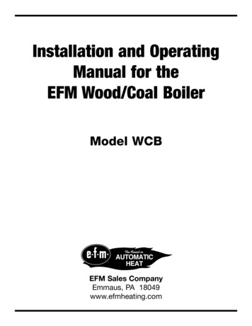
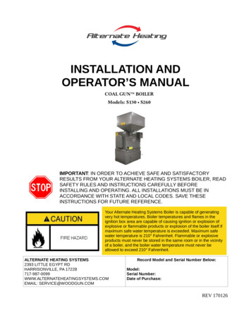
Barometric DamperNOTE: The information in the rest of this sectionis provided by Field Controls, LLC, Kinston, NorthCarolina, 252.522.3031. This information is usedwith their permission. Some information may notapply to coal burning systems. The information istaken from Field Controls, LLC website at:www.fieldcontrols.com/draftcontrol.php. See theField Controls website for specific models of draftcontrols or to place an order.Dwyer ManometerBAROMETRIC DAMPER - DRAFT CONTROLSNote: Do NOT use a barometric damper unlessexcessive draft (in excess of -.08 inches ofwater column) is present.Where excessive natural draE exists, abarometric damper is required to prevent the boilerfrom overheating. Do not operate the Coal Gun with@ue draE exceeding -.08 inches of water column. /elikelihood of this condition increases with increasedchimney height. Shorter chimneys may not require abarometric damper. Other aspects of chimneyconstruction, such as the smoothness of the innersurface of the liner and the type of liner materialused can impact draE. Liners that resist heat @owthrough the liner improve draE by keeping thechimney warmer. Warm outdoor temperatures willdecrease draE while colder ones will increase draE.Windy days will generally result in more variation inmeasured draE. Be aware of these environmentalimpacts on draE during changes in the seasonsbetween fall and winter, and winter and spring. It isbest to measure draE before concluding whether acontrol is required or not. Excessive draE can lead toan over-1ring condition. A correctly installed draEcontrol can prevent this./e standard type “M” 1eld control with a “T” isrecommended for satisfactory performance. Forproper operation and eIcient fuel consumption inoil, gas and/or coal-1red heating appliances, draEmust remain relatively constant, and above -.04inches water column, as measured with amanometer. Proper draE will normally result ingreater eIciency, with less heat wasted by escapingthrough the vent (chimney).Field draE controls maintain consistent draE bycounteracting the negative forces caused by changesin temperature and barometric pressure, and theeDects of wind. /e draE should be checked with adraE meter in the @ue pipe two to three feet abovethe boiler and before the barometric damper.-5-
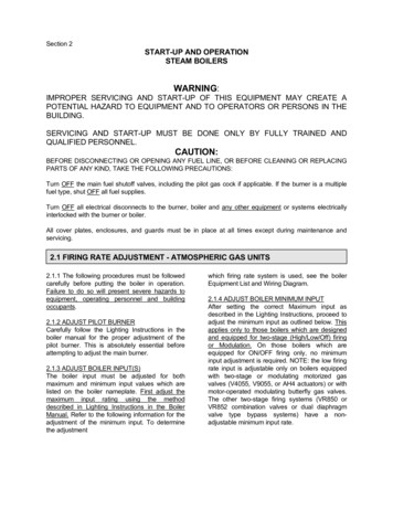
If the draft regulator is set too highit can cause the coal fire to burn outof control.NOTE: See diagram below which has beenmodified for this manual.Draft ControlHow Draft Controls Work1. Static pressure from the cooler air around theboiler exerts pressure on the outside of the furnaceor boiler, the breaching, and the stack.Choosing the Right Size Draft Control2. /e pressure diDerence between the room airand hot exhaust gasses causes products ofcombustion to @ow (draE) through the unit and torise through the breaching and chimney.1. Use a draE control the same size as the @uepipe, that is, a 6" control for a 6" round pipe, a 12"control for a 12" pipe, etc.3. When draE reaches a value higher than these ing of the control, room temperature air entersthrough the barometric draE control in the preciseamount needed to overcome the excess draEs causedby temperature variations, wind @uctuations andbarometric pressure changes.4. Combustion of fuel is completed and theprocess is stabilized. /e velocity of combustiongases through the heat exchanger is slowed so moreheat is extracted. /e unit operates more eIciently,reliably and requires less maintenance.If a barometric damper is required, use thesesimple rules of thumb to guide size selections:2. For intermediate sizes of smoke pipe, use thenext larger size draE control to provide amplecapacity. It is a simple ma er to install a roundcontrol on a pipe an inch or so larger or smaller thanthe control.3. If the @ue pipe or breaching is square, use theround equivalent. For example - on a 14" x 14"breaching use a 14" control. Li le @ow occurs in thecorners of a square pipe so that its capacity isapproximately the same as a round pipe of the samediameter.4. If the breaching is rectangular or oval,compute its cross-sectional area and select a draEcontrol having the same or a greater nominal crosssectional area. A breaching 14" high x 10" widewould have a cross-sectional area of 140 squareinches. From the table, select a 14" control with across-sectional area of 154 sq. inches.5. Where a control larger than 32" is required, usemore than one regulator with combined crosssectional areas equal to or greater than that of the-6-
breaching. When chimneys are of an unusual heightor if the draE to be maintained is either very high orvery low, it is advisable to deviate from the rules ofthumb outlined here. Refer to the larger table(following page).Control 24”28
cleanout. /e required minimums for Coal Stoker boilers when measured from the exterior of the boiler are: Rear: 30 inches to the rear (end of boiler with fan assembly) Right Side: 36 inches to the right side (when facing the front of the boiler) Le" side: 16 inches From hopper top: 18 inches Front: 24 inches, (end of boiler .