Transcription
IOMKN-2-021342-9533Cast Iron Condensing BoilersModels K N-6, KN-10, KN-16,KN-20, KN-26 and KN-30Boiler ManualInstallation and OperationInstructionsAlso read and follow:KN Control ManualMEA #444-05-EMASS Plumbers#G1-06-04-28This manual is intended only for use by a qualified heating installer/technician. Read and follow this manual, all supplements and relatedinstructional information provided with the boiler. Install, start and service the boiler only in the sequence and methods given in theseinstructions. Failure to do so can result in severe personal injury, death or substantial property damage.Do not use the boiler during construction. Construction dust and particulate, particularly drywall dust, will cause contamination ofthe burner, resulting in possible severe personal injury, death or substantial property damage. The boiler can only be operated with a dustfree air supply. Follow the instruction manual procedures to duct air to the boiler air intake. If the boiler has been contaminated by operationwith contaminated air, follow the instruction manual guidelines to clean, repair or replace the boiler if necessary.Affix these instructions near to the boiler/water heater. Instruct the building owner to retain the instructions for future use by a qualifiedservice technician, and to follow all guidelines in the User’s Information Manual.10/12 Copyright 2010 Hydrotherm
Cast Iron Condensing Boilers – Installation ManualIf the information in this manual is not followedexactly, a fire or explosion may result causingproperty, personal injury or loss of life.Do not store or use gasoline or other flammable vaporsand liquids in the vicinity of this or any other appliance.WHAT TO DO IF YOU SMELL GAS: Do not try to light any appliance. Do not touch any electrical switch. Do not use anyphone in your building. Immediately call your gas supplier from a phoneoutside of the building. Follow the gas supplier’sinstructions. If you cannot reach your gas supplier, call the firedepartment.Installation and service must be performed by a qualifiedinstaller, service agency or the gas supplier.Assurez-vous de bien suivre les instructionsdonnées dans cette notice pour réduire auminimum le risque d’incendie ou d’explosion oupour éviter tout dommoge matériel, touteblessure ou la mortNe pas entreposer ni utiliser d’essence ou ni d’autresvapeurs ou liquides inflammables à proximité de cetappareil ou de tout autre appareil.CONTENTSBefore Your Start. page 2Ratings & Capacities . page 3Location . page 3Combustion Air & Ventilation . page 3Venting Guidelines. page 5Common Vent Systems . page 12General Piping Requirements . page 13Heating System Piping . page 14Domestic Water Supply Piping . page 17Condensate Piping . page 19Gas Supply Piping . page 19Electrical Wiring . page 20Boiler Operation. page 21Operating Instructions . page 21Sequence of Operation. page 24Ignition Troubleshooting . page 26Checking & Adjustment . page 27Diagnostics . page 28Maintenance . page 29Pressure Switches . page 30Wiring . page 32Start-Up . page 35Repair Parts. page 37Warranty . page 48BEFORE YOU STARTThis manual covers the application, installation,operation and maintenance of a KN series boiler.QUE FAIRE SI VOUS SENTEZ UNE ODEUR DE GAZ: Ne pas tenter d’allumer d’appareil. Ne touchez à aucun interrupteur; ne pas vous servirdes téléphones se trouvant dans le bâtiment. Appelez immédiatement votre fournisseur de gasdepuis un voisin. Suivez les intructions du fournisseur. Si vous ne purvez rejoindre le fournisseur, appelez leservice des incendies.L’installation et l’entretien doivent être assurés par uninstallateur ou un service d’entretien qualifié ou par lefournisseur de gaz.Failure to properly vent this unit can causeexcessive amounts of carbon monoxide resultingin severe personal injury or death!Do not use automotive anti-freeze in the boilerwaterways. If the use of anti-freeze is necessaryan anti-freeze specifically formulated for hydronicheating systems must be used or damage to theboiler may occur voiding the warranty!DESIGNED AND TESTED ACCORDING TO A.S.M.E.BOILER AND PRESSURE VESSEL CODE, SECTION IVFOR A MAXIMUM ALLOWABLE WORKING PRESSUREOF 100 PSI, 700 kPa WATER.INSTALLER, THESE INSTRUCTIONS TO BE AFFIXEDADJACENT TO THE BOILER / WATER HEATER.CONSUMER, RETAIN THESE INSTRUCTIONSFUTURE REFERENCE PURPOSES.2FORTo obtain the safe, dependable, efficient operation andlong life for which this boiler was designed, theseinstructions must be read, understood and followed.The KN boiler series has been design certified by CSAfor use with natural gas under the latest revision ofANSI-Z21.13/CSA 4.9, Gas-Fired Hot Water Boilers andCAN1-3.1, Industrial and Commercial Gas FiredPackaged Boilers. Each unit has been constructed andhydrostatically tested for a maximum working pressureof 100 psi, 700 kPa, in accordance with Section IV of theA.S.M.E. Boiler and Pressure Vessel Code.All aspects of the boiler installation must conform to therequirements of the authority having jurisdiction, or, inthe absence of such requirements, to the National FuelGas Code, ANSI Z223.1/NFPA 54-latest revision. Whererequired by the authority having jurisdiction, theinstallation must conform to the Standard for Controlsand Safety Devices for Automatically Fired Boilers,ANSI/ASME CSD-1.If installed in the Commonwealth of Massachusetts, youMUST FOLLOW the additional instructions contained inHydroTherm’s instruction sheet MACODE-3. Pleaserefer to the back of this manual for required regulations.In Canada, the installation must be in accordance withthe requirements of CSA B149.1 or .2, Installation Codefor Gas Burning Appliances and Equipment.
Cast Iron Condensing Boilers – Installation ManualThe owner should maintain a record of all service workperformed with the date and a description of the workdone. Include the name of the service organization forfuture reference.Direct all questions to your HydroTherm distributor orcontact the HydroTherm Customer Service Departmentat: 260 North Elm Street, Westfield, MA 01085. Alwaysinclude the model and serial numbers from the ratingplate of the boiler in question.RATINGS & CAPACITIESBefore installing the KN boiler check the rating plate toensure that the unit has been sized properly for the job.Also ensure that the unit has been set up for the typeof gas available at the installation site. Other importantconsiderations are the availability of an adequateelectrical supply, fresh air for combustion and a suitablevent system.BOILER LOCATION1. This boiler is suitable for indoor installations only.Locate the boiler in an area that provides goodaccess to the unit. Servicing may require theremoval of jacket panels. Allow the minimumclearances between adjacent construction and theboiler as listed in Table 1.Service clearances are not mandatory, butare recommended to ensure ease of serviceshould it be required.Table 1 - ClearancesTopBackLeft SideRight SideFrontFlueClearance to Combustiblesinmm615361536153615361536153Service Clearanceinmm246102461061526152369142. An optimum site will be level, central to the pipingsystem, close to a chimney or outside wall and haveadequate fresh air for combustion. Ensure that theunit is level from front to back and from side to side.Use metal shims if leveling is required. Electrical andelectronic components must be protected fromexposure to water during operation and maintenance.DO NOT install this boiler in a location that wouldsubject any of the gas ignition and other electroniccomponents to direct contact with water or excessivemoisture during operation or servicing.3. Ensure that the floor is structurally sound and willsupport the weight of the boiler.The KN may be installed directly oncombustible flooring, but never on carpeting.4. Locate the boiler in an area that will prevent waterdamage to adjacent construction should a leakoccur or during routine maintenance.5. DO NOT place this boiler in a location that wouldrestrict the introduction of combustion air into theunit or subject it to a negative pressure unless thecombustion air is piped from the outside, see theCOMBUSTION AIR & VENTILATION section.6. NEVER place this boiler in a location that wouldsubject it to temperatures at or near freezing.Never store combustible materials, gasolineor any product containing flammable vaporsor liquids in the vicinity of the boiler. Failure tocomply with this warning can result in anexplosion or fire causing extensive propertydamage, severe personal injury or death!COMBUSTION AIR & VENTILATIONThis boiler must be supplied with combustionair in accordance with Section 5.3, Air forCombustion & Ventilation, of the latestrevision of the National Fuel Gas Code, ANSIZ223.1/NFPA 54 and all applicable localbuilding codes. Canadian installations mustcomply with CSA B149.1 or .2 InstallationCode for Gas Burning Appliances andEquipment, or applicable provisions of thelocal building codes. Failure to provideadequate combustion air for this boiler/waterheater can result in excessive levels of carbonmonoxide which can result in severe personalinjury or death!To operate properly and safely this boiler requires acontinuous supply of air for combustion. NEVER storeobjects on or around the boiler!Combustion air contaminated with fluorocarbons or other halogenated compoundssuch as cleaning solvents and refrigerantswill result in the formation of acids in thecombustion chamber. These acids will causepremature failure of the boiler voiding thewarranty!If the boiler is operated while the building isunder construction it must be protected fromwood, concrete, sheet rock and other typesof dust. Failure to properly protect the unitfrom construction dust will damage the unitvoiding the warranty!3
Cast Iron Condensing Boilers – Installation ManualBuildings will require the installation of a fresh air ductor other means of providing make-up air if the intakeair option isn't used. Any building utilizing other gasburning appliances, a fireplace, wood stove or any typeof exhaust fan must be checked for adequatecombustion air when all of these devices are inoperation at one time. Sizing of an outside air duct mustbe done to meet the requirements of all such devices.Never operate the KN in an environmentsubjected to a negative pressure unless it isDirect Vented. Failure to comply with thiswarning can result in excessive levels ofcarbon monoxide causing severe personalinjury or death!All Air From Inside The BuildingIf the boiler is to be located in a confined space theminimum clearances listed in Table 1 must bemaintained between it and any combustible construction.When installed in a confined space without the intakeair option two permanent openings communicating withan additional room(s) are required. The combinedvolume of these spaces must have sufficient volume tomeet the criteria for an unconfined space. The total airrequirements of all gas utilization equipment, fireplaces,wood stoves or any type of exhaust fan must beconsidered when making this determination. Eachopening must have a minimum free area of 1 in2/1000Btu/hr, 2200 mm2/kW based on the total input rating ofALL gas utilization equipment in the confined area. Eachopening must be no less than 100 in2, 64,516 mm2 insize. The upper opening must be within 12 in, 300 mmof, but not less than 3 in, 80 mm from, the top of theenclosure. The bottom opening must be within 12 in,300 mm of, but not less than 3 in, 80 mm from, thebottom of the enclosure.All Air From Outside The BuildingWhen installed in a confined space without the intakeair option two permanent openings communicatingdirectly with, or by ducts to, the outdoors or spaces thatfreely communicate with the outdoors must be present.The upper opening must be within 12 in, 300 mm of,but not less than 3 in, 80 mm from, the top of theenclosure. The bottom opening must be within 12 in,300 mm of, but not less than 3 in, 80 mm from, thebottom of the enclosure.Where directly communicating with the outdoors orcommunicating with the outdoors through vertical ducts,each opening shall have a minimum free area of 1in2/4000 Btu/hr, 550 mm2/kW of the total input rating of allof the equipment in the enclosure.4Where communicating with the outdoors through horizontal ducts, each opening shall have a minimum freearea of 1 in2/2000 Btu/hr, 1100 mm2/kW of the totalinput rating of all of the equipment in the enclosure.When ducts are used, they must have the same crosssectional area as the free area of the opening to whichthey connect.Table 2 - Make-up Air Duct SizingRequired Cross Sectional Duct AreaInput(MBH)1/4 in, 6.4 mmWire 2300019,344When calculating the free area necessary to meet themake-up air requirements of the enclosure,consideration must be given to the blockage effects oflouvers, grills and screens.Screens must have a minimum mesh size of 1/4 in,6.4 mm. If the free area through a louver or grill is notknown ducts should be sized per Table 2.Direct Intake Air Option - GeneralThis configuration provides combustion air directly to theboiler’s air intake using a dedicated pipe when using thedirect vent option. Combustion air can be drawn inhorizontally through an outside wall or vertically throughthe roof, see Figures 2, 3, 4 & 5. It must be sized perTable 3.Single wall galvanized smoke pipe, single wall aluminumpipe, flexible aluminum pipe, PVC or CPVC pipe can beused for the intake air pipe.Table 3 - Intake Air Pipe e Diametermm2127152152229203203
Cast Iron Condensing Boilers – Installation ManualAll joints in metal intake air systems must besecured using corrosion resistant fastenersand sealed using a suitable Silicone caulk. IfPVC or CPVC is used, the joints must becleaned with a suitable solvent and connectedusing a solvent based PVC cement. Theintake air system MUST be supported by thebuilding structure not the boiler.Direct Intake Air Option - VerticalThe maximum equivalent length for the vertical intake airpipe is 80 ft, 19.7 m for KN-6, 10, 20, 120 ft, 36.6 m forKN-16, 26, 30. Each 90 mitered elbow and the intakeair cap are equal to 10 ft, 3.3 m of straight pipe. If 90 long sweep elbows are installed use the manufacturersrecommended equivalent length.A listed, nonrestrictive intake air cap must be used. Theintake air cap must terminate as shown in Figure 4. Thepenetration point in the roof must be properly flashedand sealed.Direct Intake Air Option - HorizontalThe maximum equivalent length for the horizontalintake air pipe is 80 ft, 19.7 m for KN-6, 10, 20, 120 ft,36.6 m for KN-16, 26, 30. Each 90 mitered elbow andthe intake air terminal are equal to 10 ft, 3.3 m of straightpipe. If 90 long sweep elbows are installed use themanufacturers recommended equivalent length.Horizontal runs that exceed 5 ft, 1.5 m must besupported at 3 ft, 0.98 m intervals with overheadhangers. The intake air terminal must terminate asshown in Figures 2, 3 or 5.GENERAL VENTING GUIDELINESThe vent installation must be in accordancewith Part 7, Venting of Equipment, of theNational Fuel Gas Code, ANSI Z223.1/NFPA54-latest revision or applicable provisions ofthe local building codes. Canadian installationsmust comply with CSA B149.1 or .2 InstallationCode. Improper venting can result inexcessive levels of carbon monoxide whichcan result in severe personal injury or death!All vent systems must be fully supported by the buildingstructure and not by the boiler. Appropriate thimbles andfire-stops must be used where required.Improper installation of common positivepressure vent systems can result in excessivelevels of carbon monoxide which can causesevere personal injury or death!A barometric damper or blast gate asrequired, must be installed if a Category IIvertical vent system produces a negativedraft in excess of 0.15 in, 3.8 mm WC at theflue outlet. Size the vent system per localcodes and the vent pipe manufactuersrequirements, using generally acceptedengineering practices).VENT SYSTEM OPTIONSThe KN may be vented the following ways:1) Direct Vent (individual venting only) (page8 & 9) - Positive Pressure, Category IV uses astainless steel vent system certified to UL 1738 forinstallations in the United States, and a stainlesssteel vent system cer tified to ULC S636 forinstallations in Canada. Combustion air is pipedfrom the outdoors to the blower inlet.2) Side Wall Vent (individual venting only) (page 10)- Positive Pressure, Category IV uses a stainlesssteel vent system cer tified to UL 1738 forinstallations in the United States, and a stainlesssteel vent system cer tified to ULC S636 forinstallations in Canada. Combustion air is obtainedfrom the space in which the unit is installed.To ensure proper operation, boilers that aresidewall vented and use room air must notbe fired less than 25% input.3) Vertical Vent (individual venting only) (page10) - Positive Pressure, Category IV uses astainless steel vent system certified to UL 1738 forinstallations in the United States, and a stainlesssteel vent system cer tified to ULC S636 forinstallations in Canada. Combustion air is obtainedfrom the space in which the unit is installed.4) Vertical Vent (individual venting only) (page 11)- Negative Pressure, Category II uses stainlesssteel vent system cer tified to UL 1738 forinstallations in the United States, and a stainlesssteel vent system cer tified to ULC S636 forinstallation in Canada. Combustion air is obtainedfrom the space in which the unit is installed.5) Common Vent (page 7) - Negative Pressure,Category II (Positive Pressure, Category IV - KN-16,26, 30 only) uses a stainless steel vent systemcertified to UL 1738 for installations in the UnitedStates, and a stainless steel vent system certified toULC S636 for installations in Canada.5
Cast Iron Condensing Boilers – Installation ManualThe maximum equivalent length for the totalflue outlet vent system for Category IVconditions is 80 ft, 19.7 m for KN-6, 10, 20;120 ft, 36.6 m for KN-16, 26, 30. Use Table4 for equivalent lengths per fitting. Table 4 “Category IV Equivalent Length per Fitting”chart is meant as a guideline for preliminarysizing. If vent length approaches 75% ofmaximum length listed, an engineered ventsystem calculation must be performed.Consult factory.Table 4 - Category IV Equivalent Length per FittingKN6 KN105"6"Standard Tee1.2520 ft25 ftBoot Tee0.6510 ft15 ftCap - Low Res (UL)0.5010 ft10 ft45 w/Bird Screen0.4010 ft10 ftElbow - 90 0.3810 ft10 ftElbow - 45 0.155 ft5 ftKN20 KN26Model/Outlet DiameterK*8"8"Standard Tee1.2530 ft35 ftBoot Tee0.6515 ft15 ftCap - Low Res (UL)0.5015 ft15 ft45 w/Bird Screen0.4010 ft10 ftElbow - 90 0.3810 ft10 ftElbow - 45 0.155 ft5 ft*Equivalent lengths based on K factors and (5X)pipe diameters straight length between fittings.Model/Outlet DiameterK*KN166"25 ft15 ft10 ft10 ft10 ft5 ftKN308"35 ft15 ft15 ft10 ft10 ft5 ftDIRECT VENTPOSITIVE PRESSURE, CATEGORY IVIn this configuration the boiler blower is used to pushthe flue products to the outdoors while drawingcombustion air from the outdoors. The INTAKE AIROPTION instructions under the COMBUSTION AIR &VENTILATION SECTION must be followed!Horizontal Direct Vent Systems - Figures 2 & 3The vent materials used in positive pressure ventsystems must be certified to UL 1738 for installations inthe United States, ULC S636 for installations in Canada.To maximize the performance of single wall sheet metalvent systems locate 90 elbows as far from the boiler aspossible and from one another. For best results,horizontal vent systems should be as short and straightas possible.6The vent system must be both gas and water tight.All seams and joints in metal pipes must be joined andsealed in accordance with the vent system manufacturer’sinstructions.When horizontal vent runs exceed 5 ft, 1.5m they mustbe supported at 3 ft, 0.98 m intervals with overheadhangers. If any part of a single wall metal vent systempasses through an unheated space it must be insulatedwith insulation rated for 400 F, 212 C.Horizontal vent systems shall terminate at least 4 ft,1.3 m below, 4 ft, 1.3 m horizontally from or 1 ft,0.23 m above any door, window or gravity air inlet intoany building. It must not terminate less than 4 ft, 1.3 mhorizontally from, and in no case above or below, unlessa 4 ft, 1.3 m horizontal distance is maintained, fromelectric meters, gas meters, regulators and reliefequipment and not less than 7 ft, 2.3 m above adjacentpublic walkway. The bottom of the vent terminal(s) shallbe located at least 5 ft, 1.5 m above the air intaketerminal(s) unless there is a 5 ft, 1.5 m distance betweenthem.Avoid terminal locations likely to be affected by winds,snowdrifts, people and pets. Protect building materialsand vegetation from degradation caused by the fluegases.When running horizontal combustion air and venting forsingle or multiple units, exhaust and combustion airterminals must be installed on the same plane (outsidewall) in order to prevent pressure differences due toprevailing winds. In cold climates, double-wall or insulatedinlet pipe recommended to prevent condensation.Vertical Direct Vent Systems - see Figure 4The vent materials used in positive pressure ventsystems must be certified to UL 1738 for installations inthe United States, ULC S636 for installations in Canada.If any part of a single wall metal vent system passesthrough an unheated space it must be insulated withinsulation rated for 400 F, 204 C. Structural penetrationsmust be made using approved fire-stops.The top of a vertical vent system must extend at least51/2 ft, 1.8 m above the roof surface that it passesthrough, 4 ft, 1.3 m above the intake air cap, see Figure4. In addition the vent system must conform to thedimensions shown in Figure 4. The penetration point inthe roof must be properly flashed and sealed.The vent system must be gas tight. All seams and jointsin metal pipes must be joined and sealed in accordancewith the vent system manufacturer's instructions.Combination Direct Vent Systems - see Figure 5The boiler can be vented vertically with the intake airpiped horizontally through an outside wall. Follow theinstructions in the INTAKE AIR OPTION - HORIZONTALGUIDELINES on page 5. Also follow the generalinstructions in the COMBUSTION AIR & VENTILATIONand GENERAL VENTING GUIDELINES sections.
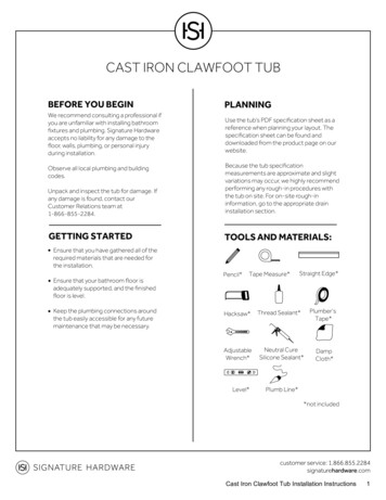
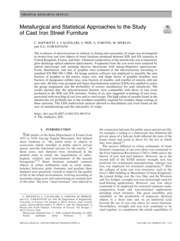
Cast Iron Condensing Boilers – Installation ManualFigure 1 - KN Series Multiple Boiler Common VentingVERTICAL CHIMNEY VENTING - When sized for a (CAT II) configuration,Vertical venting - multiple boiler a negative pressure of 0.02 to 0.15 ininstallations:WC is required in each boiler’s riserwhen all boilers are operating at fullDO NOT common vent input. A barometer damper must bemore than the following installed as illustrated. [Exception: ifnumbers of KN boilers:the vent system is designed usingKN - 6/10/16 (5) boilers accepted engineering practices, andmaximumthe design calculations prove there isKN - 20/26/30 (4) boilers no need for barometric dampers, themaximumbarometric dampers may be omitted.]Consult factory forWhen required by applicable codes,applications requiringinstall a thermal spill switch on eachmore boilers and/or usebarometric damper.an engineered ventingsystem solution.When engineered for a CAT IVconfiguration (KN-16, 26, 30 only) doIt is required that the boiler nearest not exceed a positive pressure of 0.50the vertical chimney be fired first inches WC in each boiler riser whenwhen the horizontal distance exceeds all boilers are operating at high fire.50% of the vertical distance. Refer tothe HeatNet manual on how to selectthe lead boiler.1. Connect each boiler riser to thecommon vent with a Y or boot T.2. Install an approved vent cap ateach vent termination.3. Dimensions:B breeching lengthC chimney heightD breeching diameterF riser diameter(No smaller than thedimension given in Table 4,page 6.)4. Size the chimney and breechingper local codes and vent pipemanufacturer’s requirements, usinggenerally accepted engineeringpractices. (Consult factor y forvertical heights beyond 100 ft.)7
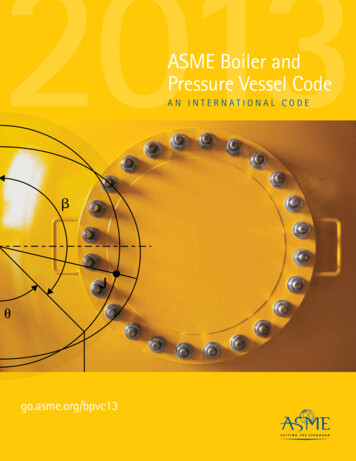
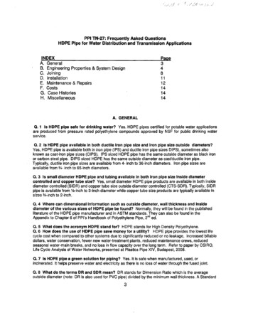
Cast Iron Condensing Boilers – Installation ManualFigure 2 - Horizontal Air Intake and Venting for a Single Direct Vent SystemFigure 3 - Horizontal Air Intake and Venting for Multiple Direct Vent Systems8
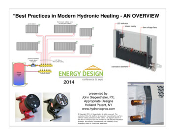
Cast Iron Condensing Boilers – Installation ManualFigure 4 - Vertical Air Intake and Venting for Direct Vent SystemFigure 5 - Combination Direct Vent Systems9
Cast Iron Condensing Boilers – Installation ManualSIDE WALL VENTPOSITIVE PRESSURE, CATEGORY IVIn this configuration the boiler blower is used to push theflue products horizontally to the outdoors, see Figure 6.To ensure proper operation, boilers that arevented sidewall and use room air must notfire less than 25% input.The air for combustion is taken from the space in whichthe unit is installed. The applicable instructions underthe COMBUSTION AIR & VENTILATION SECTIONmust be followed! The vent guidelines under theHORIZONTAL DIRECT VENT SYSTEMS section mustalso be followed.Figure 6 - Side Wall VentingVERTICAL VENT (Recommended)POSITIVE PRESSURE - CATEGORY IVIn this configuration the boiler blower is used to pushthe flue products vertically to the outdoors, see Figure7. The air for combustion is taken from the space inwhich the unit is installed. The applicable instructionsunder the COMBUSTION AIR & VENTILATIONSECTION must be followed! The vent guidelines underthe VERTICAL DIRECT VENT SYSTEMS section mustalso be followed.10Figure 7 - Vertical Positive Pressure Venting
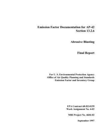
Cast Iron Condensing Boilers – Installation ManualVERTICAL VENT (Optional)NEGATIVE PRESSURE - CATEGORY IIThe vent system should be sloped up toward thechimney at a minimum rate of 1/4 in/ft, 2 cm/m.The KN is listed as a Category II appliance when ventedvertically into a listed metal AL294C S.S. chimneysystem, Figure 8. The chimney system must provide anegative pressure of 0.02 to 0.15 in, 0.51 to 3.8 mm WCat the boiler flue collar with the unit running.Always provide a minimum clearance of 6 in, 152 mmbetween single wall vent pipe and any combustiblematerials.When using a listed metal chimney systemthe chimney system manufacturer’sinstructions must be followed.Multiple boiler vent systems must bedesigned and verified by a qualifiedprofessional and stack manufacturer. Thevent system must prevent backflow ofexhaust gas through idle boilers.Failure to maintain minimum clearancesbetween vent connectors and anycombustible material can result in a firecausing extensive property damage, severepersonal injury or death!When more than one appliance is connected to the samechimney system the system must be large enough tosafely vent the combined output of all of the appliances.Exit cones are favorable when usedto increase the velocity of the fluegas exiting the stack and, may alsohelp, in cold climates, to reduce icebuild-up. Exit cone terminations mustbe supplied by others, installed permanufacturer’s instructions, and meetlocal and federal code.Table 5 lists the equivalent breeching and chimneysizes required for a single boiler installation.Figure 8 - Vertical Venting with a Metal Chimney SystemIf an appliance using any type of amechanical draft system operating underpositive pressure is connected to a chimneyflue, never connect any other appliances tothis flue. Doing so can result in excessivelevels of carbon monoxide which can causesevere personal injury or death!generic exit coneNote:1) All buildingstructuralmodificationsby others.2) Firestopping perlocal buildingcodes.Table 5 - Equivalent Breeching & Chimney Size,Negative Pressure - Single BoilerModelSize60010001600200026003000Breech & Flue Diameterin2mm282041230514356143561435614356These sizes are based on a 20 ft, 6.1mchimney height.Vent ConnectionsLocate the boiler as close to the chimney system aspossible. Use the shortest, straightest vent connectorpossible for the installation. If horizontal runs exceed5 ft, 1.5 m they must be supported at 3 ft, 0.9 mintervals with overhead hangers. Use the appropriatevent connector of the same diameter as the flue collarto connect the boiler to a listed metal chimney system.Follow the chimney system manufacturer’s instructionsfor proper assembly.11
Cast Iron Condensing Boilers – Installation ManualDans la mesure du possible, fermer toutes les porteset les fenêtres du bâtiment et toutes les portes entrel'espace où les appareils toujours raccordés dusystème d'évacuation sont installés et les autresespaces du bâtiment. Mettre en marche lessécheuses, tous les appareils non raccordés ausystème d'évacuation commun et tous lesventilateurs d'extraction comme les hottes decuisinère et les ventilateurs des salles de bain.S'assurer que ces ventilateurs fonctionnent à lavitesse maximale. Ne pas faire fonctionner lesventi
The KN boiler series has been design certifi ed by CSA for use with natural gas under the latest revision of ANSI-Z21.13/CSA 4.9, Gas-Fired Hot Water Boilers and CAN1-3.1, Industrial and Commercial Gas Fired Packaged Boilers. Each unit has been constructed and