Transcription
PPI TN·27: Frequently Asked QuestionsHOPE Pipe for Water Distribution and Transmission ApplicationsINDEXA. GeneralB. Engineering Properties & System DesignC. JoiningD. InstallationE. Maintenance & RepairsF. CostsG. Case HistoriesH. MiscellaneousPage3481112141414A. GENERALQ. 1 Is HOPE pipe safe for drinking water? Yes. HDPE pipes certified for potable water applicationsare produced from pressure rated polyethylene compounds approved by NSF for public drinking waterservice.Q.2 Is HOPE pipe available in both ductile iron pipe size and iron pipe size outside diameters?Yes, HDPE pipe is available both in iron pipe (IPS) and ductile iron pipe sizes DIPS), sometimes alsoknown as cast-iron pipe sizes (CIPS). IPS sized HDPE pipe has the same outside diameter as black ironor carbon steel pipe. DIPS sized HDPE has the same outside diameter as cast/ductile iron pipe.Typically, ductile iron pipe sizes are available from 4- inch to 36-lnch diameters. Iron pipe sizes areavailable from %- inch to 65-inch diameters.Q. 3 Is small diameter HOPE pipe and tubing available in both iron pipe size Inside diametercontrolled and copper tube size? Yes, small diameter HDPE pipe products are available in both insidediameter controlled (SIDR) and copper tube size outside diameter controlled (CTS-SDR). Typically, SIDRpipe is available from V2-inch to 3-inch diameter while copper tube size products are typically available insizes %-inch to 2-inch.Q.4 Where can dimensional information such as outside diameter, wall thickness and insidediameter of the various sizes of HOPE pipe be found? Normally, they will be found in the publishedliterature of the HDPE pipe manufacturer and in ASTM standards. They can also be found in theAppendix to Chapter 6 of PPI's Handbook of Polyethylene Pipe, 2nd ed.Q.5 What does the acronym HOPE stand for? HDPE stands for High Density Polyethylene.Q.6 How does the use of HOPE pipe save money for a utility? HDPE pipe provides the lowest lifecycle cost when compared to other systems due to significantly reduced or no leakage, increased billabledollars, water conservation, fewer new water-treatment plants, reduced maintenance crews, reducedseasonal water-main breaks, and no loss in flow capacity over the long term. Refer to paper by CSIRO,Life Cycle Analysis of Water Networks, presented at Plastics Pipe XIV, Budapest, 2008.Q. 7 Is HOPE pipe a green solution for piping? Yes. It is safe when manufactured, used, orincinerated. It helps preserve water and electricity as there is no loss of water through the fused joint.Q. 8 What do the terms OR and SOR mean? DR stands for Dimension Ratio which is the averageoutside diameter (note: DR is also used for PVC pipe) divided by the minimum wall thickness. A Standard3
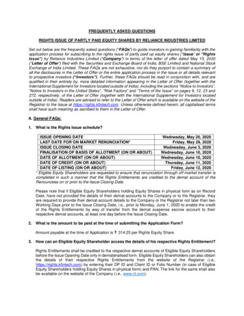
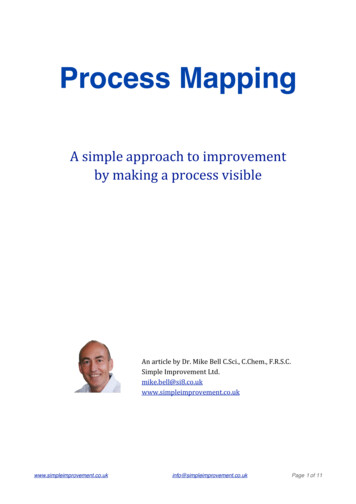
61249ChapterDes ign o f PE Piping S), lem sAppendi x A.lPIPE WEIGHTS AND DIMENSIONS ness(t)DR·In.in.lb. 1.192213.560.1890.97800NominalIn.346I .56.450.2121.954
I250 Chapter 6Design of PE Piping 14I ActualIn.IIII.9,05011.10013.20015.300Weight(w)lb. 732.514.300.4719.607
Chapter61251Design of PE Piping 63.55351.39043.06700Nominal 1 ActualIn.In.16I17.400,Ib. per32.5791113.5182024I19 5001 23.73219.14750.61841.49533.85827.317
2521 DesignChapter 6of PE Piping )DR'"In.In.lb. 28.011.88277.86900Nelmln.1In.30I 1.23152.0B632.529.910.98542.023 These DRs (7.3. 9. 11. 13.5, 17. 21, 26. 32.5) are from the standarddimension ratio (SDR) series established by ASTM F 412.51
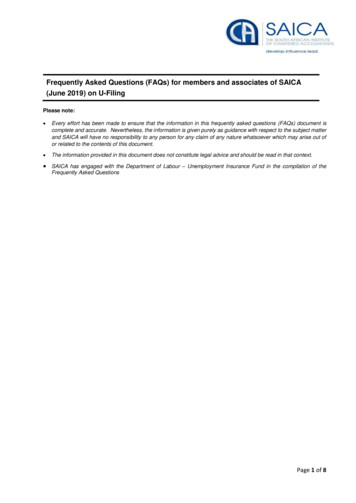
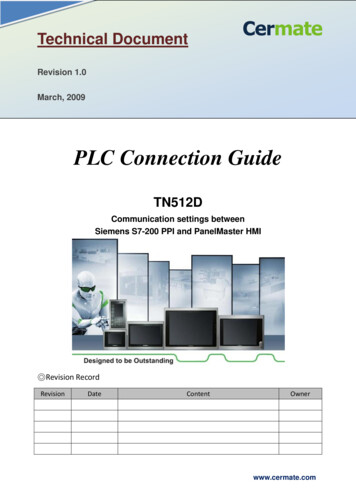
61253ChapterDesign of PE Piping SystemsAppendix A.2.PIPE WEIGHTS AND DIMENSIONS .50.690.0730.077ODNominalIn.1/23/4111/4I ActualIn.IIII0.8401.0501.3151.660Weight(w)lb. 51.400.1230.259
254/ Chapter 6Design of PE Piping ght(w)lb. 0.9320.764263.210.1350.6231.609
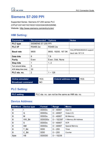
61255ChapterDesign of PE Piping SystemsPipeInsidediameter(d)ODNa ! III)I··.··.··Actual';ltl. .'. '. ,., ss(t)Ii. 3.26993.440.5002.7379.33.472.660113.630.4840.409 2552.23332.56.190.2041.801
256/ Chapter 6Design of PE Piping t(t)(w)lb. 9032.511.920.3926.6718.269
61257ChapterDesign of PE Piping ght(t)(w)DRIn.In.lb. 3.296
2581 Chapter6Design of PE Pipi ng Systems00N.tlmlnal"In.202224I nimumWallThickness(II)(t)Weight(w)fli.tn.lb. 30.73823.638
61259ChapterDesign of PE Piping I mWallThickness(t)Weight(w)DRIn.In.lb. .539.261.29272.392
I260 Chapter 6Design of PE Piping lb. 8
1921 Chapter 6Design of PE Piping SystemsCalculationsSection 3 describes how to calculate the soil pressure acting on PE pipe due to soilweight and surface loads, how to determine the resulting deflection based on pipeand soil properties, and how to calculate the allowable (safe) soil pressure for wallcompression (crushing) and ring buckling for PE pipe.Detailed calculations are not always necessary to determine the suitability of aparticular PE pipe for an application. Pressure pipes that fall within the DesignWindow given in AWWA M-55 "PE Pipe - Design and Installation" regardingpipe DR, installation, and burial depth meet specified deflection limits for PE pipe,have a safety factor of at least 2 against buckling, and do not exceed the allowablematerial compressive stress for PE. Thus, the designer need not perform extensivecalculations for pipes that are sized and installed in accordance with the DesignWindow.AWWA M-55 Design WindowAWWA M-55, "PE Pipe - Design and Installation", describes a Design Window.Applications that fall within this window require no calculations other thanconstrained buckling per Equation 3-15. It turns out that if pipe is limited to DR 21or lower as in Table 3-1, the constrained buckling calculation has a safety factor of atleast 2, and no calculations are required.The design protocol under these circumstances (those that fall within the AWWADesign Window) is thereby greatly Simplified. The designer may choose to proceedwith detailed analysis of the burial design and utilize the AWWA Design Windowguidelines as a means of validation for his design calculations and commensuratesafety factors. Alternatively, he may proceed with confidence that the burial designfor these circumstances (those outlined within the AWWA Design Window) hasalready been analyzed in accordance with the guidelines presented in this chapter.The Design Window specifications are: Pipe made from stress-rated PE material. Essentially no dead surface load imposed over the pipe, no ground water abovethe surface, and provisions for preventing flotation of shallow cover pipe havebeen provided . The embedment materials are coarse-grained, compacted to at least 85% StandardProctor Density and have an E' of at least 1000 psi. The native soil must be stable;in other words the native soil must have an E' of at least 100.0 psi. See Table 3-7. The unit weight of the native soil does not exceed 120. pef. The pipe is installed in accordance with manufacturer's recommendations forcontrolling shear and bending loads and minimum bending radius, and installed
Chapter &/ :1.93Design of PE Piping Systemsin accordance with ASTM D2774 for pressure pipes or ASTM D2321 for nonpressure pipes. Minimum depth of cover is 2 ft (0.61 m); except when subject to AASHTO H20truck loadings, in which case the minimum depth of cover is the greater of 3 ft(0.9 m) or one pipe diameter. Maximum depth of cover is 25 ft (7.62 m).TABLE 3-1AWWA M-55 Design Window Maximum and Minimum Depth ofCover Requiring No CalculationsDRMin. Depth ofCover With H2OLoadMin. Depth ofCover WithoutH20 LoadMaximumDepth of Cover7.33ft2ft25 ft93ft2ft25 ft113ft2ft25 ft13.53ft2ft25 ft173ft2ft25 fI213ft2ft25 ft Limiting depths where no calculations are required. Pipes are suitable for deeper depth provideda sufficient E' (1.000 psi or more) Is accomplished during Installations. Calculations would be requiredfor depth greater than 25 ft.Installation CategoriesFor the purpose of calculation, buried installations of PE pipe can be separatedinto four categories depending on the depth of cover, surface loading, groundwaterlevel and pipe diameter. Each category involves slightly different equations fordetermining the load on the pipe and the pipe's response to the load. The boundariesbetween the categories are not definite, and engineering judgment is required toselect the most appropriate category for a specific installation. The categories are:1. Standard Installation-Trench or Embankment installation with a maximumcover of 50 ft with or without traffic, rail, or surcharge loading. To be in thiscategory, where live loads are present the pipe must have a minimum cover ofat least one diameter or 18" whichever is greater. Earth pressure applied to thepipe is found using the prism load (geostatic soil stress). The Modified IowaFormula is used for calculating deflection. Crush and buckling are performancelimits as well. The Standard Installation section also presents the AWWA "DesignWindow."2. Shallow Cover Vehicular Loading Installation applies to pipes buried at adepth of at least 18" but less than one pipe diameter. This installation category
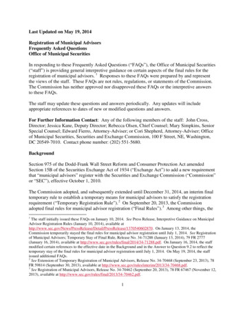
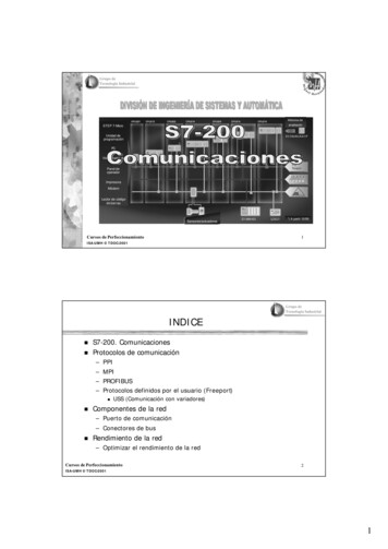
1941Chapter 6Design of PE Piping Systemsuses the same equations as the Standard Installation but with an additionalequation relating wheel load to the pipe's bending resistance and the soil'ssupporting strength.3. Deep Fill Installation applies to embankments with depths exceeding 50 ft.The soil pressure calculation may be used for profile pipe in trenches lessthan 50 ft. The Deep Fill Installation equations differ from the StandardInstallation equations by considering soil pressure based on armored, calculatingdeflection from the Watkins-Gaube Graph, and calculating budding with theMoore-Selig Equation.4. Shallow Cover Flotation Effects applies to applications where insufficientcover is available to either prevent flotation or hydrostatic collapse. Hydrostaticbuckling is introduced in this chapter because of its use in subsurface design.Section 3 of the Design Chapter is limited to the design of PE pipes buried intrenches or embankments. The load and pipe reaction calculations presented maynot apply to pipes installed using trench less technologies such as pipe burstingand directional drilling. These pipes may not develop the same soil support aspipe installed in a trench. The purveyor of the trenchless technology should beconsulted for piping design information. See the Chapter on "PE Pipe for HorizontalDirectional Drilling" and ASTM F1962, Use of Maxi-Horizontal Directional Drilling(HOD) for Placement of Polyethylene Pipe or Conduit Under Obstacles, Including RiverCrossings for additional information on design of piping installed using directionaldrilling.ElG.lA E.Ilt.ll RING DEFLECTIONRING COMPRESSIONRING BUCKLINGFigure 3-1 Performance Limits for Buried PE PipeDesign ProcessThe interaction between pipe and soil, the variety of field-site soil conditions, andthe range of available pipe Dimension Ratios make the design of buried pipe seemchallenging. This section of the Design Chapter has been written with the intentof easing the designer's task. While some very sophisticated design approaches for
known as cast-iron pipe sizes (CIPS). IPS sized HDPE pipe has the same outside diameter as black iron or carbon steel pipe. DIPS sized HDPE has the same outside diameter as cast/ductile iron pipe. Typically, ductile iron pipe sizes are available from 4-inch to 36-lnch diameters. Iron pipe sizes are available from %-inch to 65-inch diameters.