Transcription
Emission Factor Documentation for AP-42Section 13.2.6Abrasive BlastingFinal ReportFor U. S. Environmental Protection AgencyOffice of Air Quality Planning and StandardsEmission Factor and Inventory GroupEPA Contract 68-D2-0159Work Assignment No. 4-02MRI Project No. 4604-02September 1997
Emission Factor Documentation for AP-42Section 13.2.6Abrasive BlastingFinal ReportFor U. S. Environmental Protection AgencyOffice of Air Quality Planning and StandardsEmission Factor and Inventory GroupResearch Triangle Park, NC 27711Attn: Mr. Ron Myers (MD-14)EPA Contract 68-D2-0159Work Assignment No. 4-02MRI Project No. 4604-02September 1997
NOTICEThe information in this document has been funded wholly or in part by the United StatesEnvironmental Protection Agency under Contract No. 68-D2-0159 to Midwest Research Institute. It hasbeen reviewed by the Office of Air Quality Planning and Standards, U. S. Environmental Protection Agency,and has been approved for publication. Mention of trade names or commercial products does not constituteendorsement or recommendation for use.ii
PREFACEThis report was prepared by Midwest Research Institute (MRI) for the Office of Air QualityPlanning and Standards (OAQPS), U. S. Environmental Protection Agency (EPA), under ContractNo. 68-D2-0159, Work Assignment Nos. 2-01 and 4-02. Mr. Ron Myers was the requester of the work.Approved for:MIDWEST RESEARCH INSTITUTERoy NeulichtProgram ManagerEnvironmental Engineering DepartmentJeff ShularDirector, Environmental EngineeringDepartmentSeptember, 1997iii
iv
TABLE OF CONTENTSPage1. INTRODUCTION . . . . . . . . . . . . . . . . . . . . . . . . . . . . . . . . . . . . . . . . . . . . . . . . . . . . . . . . . . . . . . .1-12. INDUSTRY AND PROCESS DESCRIPTION . . . . . . . . . . . . . . . . . . . . . . . . . . . . . . . . . . . . . . . .2.1 INDUSTRY CHARACTERIZATION . . . . . . . . . . . . . . . . . . . . . . . . . . . . . . . . . . . . . . . . . .2.2 PROCESS DESCRIPTION . . . . . . . . . . . . . . . . . . . . . . . . . . . . . . . . . . . . . . . . . . . . . . . . . . .2.2.1 Types of Abrasives . . . . . . . . . . . . . . . . . . . . . . . . . . . . . . . . . . . . . . . . . . . . . . . . . . . .2.2.2 Blasting Methods . . . . . . . . . . . . . . . . . . . . . . . . . . . . . . . . . . . . . . . . . . . . . . . . . . . . .2.3 DUST CONTROL TECHNIQUES . . . . . . . . . . . . . . . . . . . . . . . . . . . . . . . . . . . . . . . . . . . . .2.3.1 Blast Enclosures . . . . . . . . . . . . . . . . . . . . . . . . . . . . . . . . . . . . . . . . . . . . . . . . . . . . . .2.3.2 Vacuum Blasters . . . . . . . . . . . . . . . . . . . . . . . . . . . . . . . . . . . . . . . . . . . . . . . . . . . . . .2.3.3 Drapes . . . . . . . . . . . . . . . . . . . . . . . . . . . . . . . . . . . . . . . . . . . . . . . . . . . . . . . . . . . . . .2.3.4 Water Curtains . . . . . . . . . . . . . . . . . . . . . . . . . . . . . . . . . . . . . . . . . . . . . . . . . . . . . . .2.3.5 Wet Blasting . . . . . . . . . . . . . . . . . . . . . . . . . . . . . . . . . . . . . . . . . . . . . . . . . . . . . . . . .2.3.6 Centrifugal Blasters . . . . . . . . . . . . . . . . . . . . . . . . . . . . . . . . . . . . . . . . . . . . . . . . . . .2.4 REFERENCES FOR SECTION 2 . . . . . . . . . . . . . . . . . . . . . . . . . . . . . . . . . . . . . . . . . . . . . .2-12-12-12-12-22-92-92-92-92-92-112-132-133. GENERAL DATA REVIEW AND ANALYSIS . . . . . . . . . . . . . . . . . . . . . . . . . . . . . . . . . . . . . . .3.1 LITERATURE SEARCH AND SCREENING . . . . . . . . . . . . . . . . . . . . . . . . . . . . . . . . . . . .3.2 DATA QUALITY RATING SYSTEM . . . . . . . . . . . . . . . . . . . . . . . . . . . . . . . . . . . . . . . . . .3.3 EMISSION FACTOR QUALITY RATING SYSTEM . . . . . . . . . . . . . . . . . . . . . . . . . . . . .3.4 REFERENCES FOR SECTION 3 . . . . . . . . . . . . . . . . . . . . . . . . . . . . . . . . . . . . . . . . . . . . . .3-13-13-13-23-34. EMISSION FACTOR DEVELOPMENT . . . . . . . . . . . . . . . . . . . . . . . . . . . . . . . . . . . . . . . . . . . .4.1 REVIEW OF SPECIFIC DATA SETS . . . . . . . . . . . . . . . . . . . . . . . . . . . . . . . . . . . . . . . . . .4.1.1 Reference 1 . . . . . . . . . . . . . . . . . . . . . . . . . . . . . . . . . . . . . . . . . . . . . . . . . . . . . . . . . .4.1.2 Reference 2 . . . . . . . . . . . . . . . . . . . . . . . . . . . . . . . . . . . . . . . . . . . . . . . . . . . . . . . . . .4.1.3 Reference 3 . . . . . . . . . . . . . . . . . . . . . . . . . . . . . . . . . . . . . . . . . . . . . . . . . . . . . . . . . .4.1.4 Reference 4 . . . . . . . . . . . . . . . . . . . . . . . . . . . . . . . . . . . . . . . . . . . . . . . . . . . . . . . . . .4.1.5 Reference 5 . . . . . . . . . . . . . . . . . . . . . . . . . . . . . . . . . . . . . . . . . . . . . . . . . . . . . . . . . .4.1.6 Reference 6 . . . . . . . . . . . . . . . . . . . . . . . . . . . . . . . . . . . . . . . . . . . . . . . . . . . . . . . . . .4.2 RESULTS OF DATA ANALYSIS . . . . . . . . . . . . . . . . . . . . . . . . . . . . . . . . . . . . . . . . . . . . .4.3 DEVELOPMENT OF CANDIDATE EMISSION FACTORS . . . . . . . . . . . . . . . . . . . . . . . .4.4 REFERENCES FOR SECTION 4 . . . . . . . . . . . . . . . . . . . . . . . . . . . . . . . . . . . . . . . . . . . . . .4-14-14-24-24-24-34-34-34-34-74-115. PROPOSED AP-42 SECTION 13.2.6 . . . . . . . . . . . . . . . . . . . . . . . . . . . . . . . . . . . . . . . . . . . . . . .5-1v
LIST OF -7.PageSuction blast nozzle assembly . . . . . . . . . . . . . . . . . . . . . . . . . . . . . . . . . . . . . . . . . . . . . . . .Suction-tape blasting machine . . . . . . . . . . . . . . . . . . . . . . . . . . . . . . . . . . . . . . . . . . . . . . . .Pressure-type blasting machine . . . . . . . . . . . . . . . . . . . . . . . . . . . . . . . . . . . . . . . . . . . . . . .Wet blasting machine . . . . . . . . . . . . . . . . . . . . . . . . . . . . . . . . . . . . . . . . . . . . . . . . . . . . . . .Adapter nozzle converting a dry blasting unit to a wet blasting unit . . . . . . . . . . . . . . . . . . .Hydraulic blasting nozzle . . . . . . . . . . . . . . . . . . . . . . . . . . . . . . . . . . . . . . . . . . . . . . . . . . . .Schematic of vacuum blaster head . . . . . . . . . . . . . . . . . . . . . . . . . . . . . . . . . . . . . . . . . . . . .Nozzle for air abrasive wet blast . . . . . . . . . . . . . . . . . . . . . . . . . . . . . . . . . . . . . . . . . . . . . .Water curtain device for abrasive blast nozzle . . . . . . . . . . . . . . . . . . . . . . . . . . . . . . . . . . . .2-42-42-52-62-62-62-102-112-12LIST OF .4-7.4-7.4-8.4-9.4-10.MEDIA COMMONLY USED IN ABRASIVE BLASTING . . . . . . . . . . . . . . . . . . . . . . . .FLOW RATE OF SAND THROUGH A BLASTING NOZZLE AS AFUNCTION OF NOZZLE PRESSURE AND INTERNAL DIAMETER . . . . . . . . . . . . . .BULK DENSITY OF COMMON ABRASIVES . . . . . . . . . . . . . . . . . . . . . . . . . . . . . . . . .REFERENCE DOCUMENTS REVIEWED DURING LITERATURE SEARCH . . . . . . .SUMMARY OF TEST DATA FOR ABRASIVE BLASTING OPERATIONS . . . . . . . .SUMMARY OF AVAILABLE CONTROL EFFICIENCY DATA FOR ABRASIVEBLASTING OPERATIONS . . . . . . . . . . . . . . . . . . . . . . . . . . . . . . . . . . . . . . . . . . . . . . . . .SUMMARY OF PM TEST DATA FROM REFERENCE 1 . . . . . . . . . . . . . . . . . . . . . . . .SUMMARY OF EMISSION FACTORS FOR PM METALS . . . . . . . . . . . . . . . . . . . . . .SUMMARY OF EMISSION FACTORS FOR PM-10 METALS . . . . . . . . . . . . . . . . . . .SUMMARY OF EMISSION FACTORS FOR PM-2.5 METALS . . . . . . . . . . . . . . . . . . .SUMMARY OF EMISSION FACTORS FOR PM-2.5 METALS . . . . . . . . . . . . . . . . . . .CANDIDATE PM-10 AND PM-2.5 EMISSION FACTORS . . . . . . . . . . . . . . . . . . . . . . .CANDIDATE TOTAL PM EMISSION FACTORS DIFFERENTIATEDBY WIND SPEED . . . . . . . . . . . . . . . . . . . . . . . . . . . . . . . . . . . . . . . . . . . . . . . . . . . . . . . . .CANDIDATE EMISSION FACTOR FOR GARNET BLASTING . . . . . . . . . . . . . . . . . .vi2-22-82-84-14-44-64-84-94-94-104-104-104-104-11
1. INTRODUCTIONThe document Compilation of Air Pollutant Emission Factors (AP-42) has been published by theU. S. Environmental Protection Agency (EPA) since 1972. Supplements to AP-42 are issued to add newemission source categories and to update existing emission factors. The EPA also routinely updates AP-42 inresponse to the needs of Federal, State, and local air pollution control programs and industry.An emission factor relates the quantity (weight) of pollutants emitted to a unit of source activity.Emission factors reported in AP-42 are used to:1. Estimate areawide emissions.2. Estimate emissions for a specific facility.3. Evaluate emissions relative to ambient air quality.This report provides background information from test reports and other information to supportpreparation of a new AP-42 section for abrasive blasting. The information in the proposed AP-42 section isbased on a review of the available literature for particulate phase air pollutants produced by abrasive blastingoperations.This report contains five sections. Following the introduction, Section 2 describes abrasive blastingequipment, practices, and allied processes. Section 3 describes data collection and rating procedures, andSection 4 describes the emission factor development. Section 5 presents the proposed AP-42 section.1-1
2. INDUSTRY AND PROCESS DESCRIPTION2.1 INDUSTRY CHARACTERIZATION1Abrasive blasting is used for a variety of surface cleaning and texturing operations, mostly involvingmetallic target materials. Sand is the most widely used blasting abrasive. Other abrasive materials includecoal slag, smelter slags, mineral abrasives, metallic abrasives, and synthetic abrasives. Industries that useabrasive blasting include the shipbuilding industry, automotive industry, and other industries that involvesurface preparation and painting. The majority of shipyards no longer use sand for abrasive blasting becauseof concerns about silicosis, a condition caused by respiratory exposure to crystalline silica. In 1991, about4.5 million tons of abrasives, including 2.5 million tons of sand, 1 million tons of coal slag, 500 thousandtons of smelter slag, and 500 thousand tons of other abrasives, were used for domestic abrasive blastingoperations.2.2 PROCESS DESCRIPTION1-8The following sections briefly describe the types of abrasives, blasting methods, and dust controltechniques commonly used in outdoor abrasive blasting.2.2.1 Types of Abrasives1-2Abrasive materials are generally classified as: sand, slag, metallic shot or grit, synthetic, or other.The cost and properties associated with the abrasive material dictate its application. The following discussesthe general classes of common abrasives.Silica sand is commonly used for abrasive blasting where reclaiming is not feasible, such as inunconfined abrasive blasting operations. Sand has a rather high breakdown rate, which can result insubstantial dust generation. Worker exposure to free crystalline silica is of concern when silica sand is usedfor abrasive blasting.Coal and smelter slags are commonly used for abrasive blasting at shipyards. Black BeautyTM,which consists of crushed slag from coal-fired utility boilers, is a commonly used slag. Slags have theadvantage of low silica content, but have been documented to release other contaminants, includinghazardous air pollutants (HAP), into the air.Metallic abrasives include cast iron shot, cast iron grit, and steel shot. Cast iron shot is hard andbrittle and is produced by spraying molten cast iron into a water bath. Cast iron grit is produced by crushingoversized and irregular particles formed during the manufacture of cast iron shot. Steel shot is produced byblowing molten steel. Steel shot is not as hard as cast iron shot, but is much more durable. These materialstypically are reclaimed and reused.Synthetic abrasives, such as silicon carbide and aluminum oxide, are becoming popular substitutesfor sand. These abrasives are more durable and create less dust than sand. These materials typically arereclaimed and reused.Other abrasives include mineral abrasives (such as garnet, olivine, and staurolite), cut plastic, glassbeads, crushed glass, and nutshells. As with metallic and synthetic abrasives, these other abrasives are2-1
generally used in operations where the material is reclaimed. Mineral abrasives are reported to createsignificantly less dust than sand and slag abrasives.The type of abrasive used in a particular application is usually specific to the blasting method. Dryabrasive blasting is usually done with sand, aluminum oxide, silica carbide, metallic grit, or shot. Wetblasting is usually done with sand, glass beads, or any materials that will remain suspended in water.Table 2-1 lists common abrasive materials and their applications.TABLE 2-1. MEDIA COMMONLY USED IN ABRASIVE BLASTING2Type of mediumSizes normally availableApplicationsGlass beads8 to 10 sizes from 30- to 440-mesh;also many special gradationsDecorative blending; light deburring;peening; general cleaning; texturing;noncontaminatingAluminum oxide10 to 12 sizes from 24- to 325-meshFast cutting; matte finishes; descalingand cleaning of coarse and sharptexturesGarnet6 to 8 sizes (wide-band screening) from16- to 325-meshNoncritical cleaning and cutting;texturing; noncontaminating forbrazing steel and stainless steelCrushed glass5 sizes (wide-band screening) from 30to 400-meshFast cutting; low cost; short life;abrasive; noncontaminatingSteel shot12 or more sizes (close gradation) from8- to 200-meshGeneral-purpose rough cleaning(foundry operation, etc.); peeningSteel grit12 or more sizes (close gradation) from10- to 325-meshRough cleaning; coarse textures;foundry welding applications; sometexturingCut plastic3 sizes (fine, medium, coarse); definitesize particlesDeflashing of thermoset plastics;cleaning; light deburringCrushed nutshells6 sizes (wide-band screening)Deflashing of plastics; cleaning; verylight deburring; fragile parts2.2.2 Blasting Methods2-8Abrasive blasting systems typically include three basic components: an abrasive container (i.e.,blasting pot), a propelling device, and an abrasive blasting nozzle(s). The exact equipment used depends onthe application.The three propelling methods used in abrasive blasting systems are: centrifugal wheels, air pressure,or water pressure. Centrifugal wheel systems use centrifugal and inertial forces to mechanically propel theabrasive media.3 Air blast systems use compressed air to propel the abrasive to the surface being cleaned.4Finally, the water blast method uses either compressed air or high pressure water.52-2
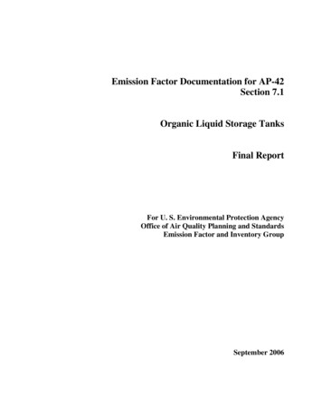
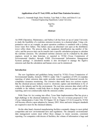
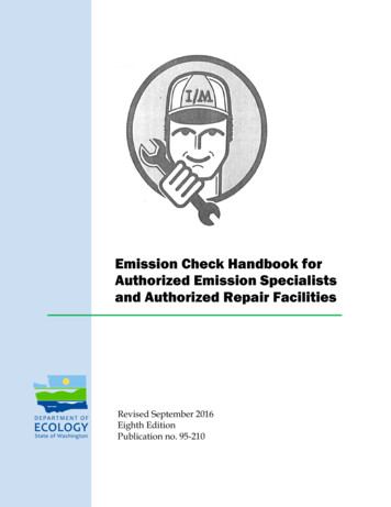
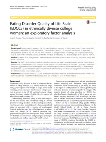
The compressed air suction, the compressed air pressure, and the wet abrasive blasting systems utilize the airblast method. Hydraulic blasting systems utilize the water blast method.In compressed air suction systems, two rubber hoses are connected to a blasting gun. One hose isconnected to the compressed-air supply and the other is connected to the bottom of the abrasive supply tankor “pot.” The gun (Figure 2-1a) consists of an air nozzle that discharges into a larger nozzle. The highvelocity air jet (expanding into the larger nozzle) creates a partial vacuum in the chamber. This vacuumdraws the abrasive into the outer nozzle and expels it through the discharge opening. Figure 2-1b shows atypical suction type blasting machine.The compressed air pressure system consists of a pressure tank (pot) in which the abrasive iscontained. The use of a pressure tank forces abrasive through the blast hose rather than siphoning it asdescribed above. The compressed air line is connected to both the top and bottom of the pressure tank. Thisallows the abrasive to flow by gravity into the discharge hose without loss of pressure (see Figure 2-2).Finally, wet abrasive blasting systems (Figure 2-3a) use a specially designed pressure tank. Themixture of abrasive and water is propelled by compressed air. An alternate method uses a pressure tank anda modified abrasive blasting nozzle. This modified abrasive blasting nozzle is shown in Figure 2-3b.Hydraulic blasting incorporates a nozzle similar to that described above for air suction systems,except that high pressure water is used as the propelling media instead of compressed air. A diagram of thistype of nozzle is shown in Figure 2-4.Pressure blast systems generally give a faster, more uniform finish than suction blast systems. Theyalso produce high abrasive velocities with less air consumption than suction systems. Pressure blast systemscan operate at pressures as low as 1 psig to blast delicate parts and up to 125 psig to handle the mostdemanding cleaning and finishing operations.2Suction blast systems are generally selected for light-to-medium production requirements, limitedspace, and moderate budgets. These systems can blast continuously without stopping for abrasive changesand refills.2The amount of sand used during blasting operations can be estimated using Table 2-2. By knowingthe inside diameter of the nozzle (inches) and the air pressure supplied (psig), the sand flow rate is provided.For different abrasives and nozzle diameters, Equation 2-1 can be used.22-3
Figure 2-1a. Suction blast nozzle assembly.Figure 2-1b. Suction-tape blasting machine.2-4
Figure 2-2. Pressure-type blasting machine.2-5
Figure 2-3a. Wet blasting machine.Figure 2-3b. Adapter nozzle converting a dry blasting unit to a wet blasting unit.2-6
Figure 2-4. Hydraulic blasting nozzle.2-7
2@ ' m@ (Da ) DamasDs(Ds )2(2-1)where:@ mass flow rate (lb/hr) of abrasive with nozzle internal diameter Dmaa@m mass flow rate (lb/hr) of sand with nozzle internal diameter D from Table 2-2ssDa Ds Ds Da actual nozzle internal diameter (in.)nozzle internal diameter (in.) from Table 2-2bulk density of sand (lb/ft3)bulk density of abrasive (lb/ft3)TABLE 2-2. FLOW RATE OF SAND THROUGH A BLASTING NOZZLE AS AFUNCTION OF NOZZLE PRESSURE AND INTERNAL DIAMETER2Sand flow rate through nozzle, lb/hrNozzleinternaldiameter, in.Nozzle pressure, 02,9003,3403,7804,2004,6405,060The densities of several different abrasives are shown in Table 2-3.TABLE 2-3. BULK DENSITY OF COMMON ABRASIVES2Density, lb/ft3Type of abrasiveAluminum oxides160Sand99Steel4872-8
2.3 DUST CONTROL TECHNIQUES2,4,6,7A variety of techniques have been used to contain and recover the debris generated during abrasivecleaning operations. These techniques may be categorized into the following: blast enclosures, vacuumblasters, drapes, water curtains, wet blasters, and centrifugal blasters. Brief descriptions of each are providedbelow. A more detailed discussion of each method can be found in Reference 6.2.3.1 Blast EnclosuresBlast enclosures are designed to completely enclose one or more abrasive blast operations, therebyconfining the blast debris. The enclosure floor is usually equipped with funnels to divert the captured debrisinto adjacent trucks. In one design, a ventilation system is used to remove the airborne dust from theenclosure with the particles removed from the effluent airstream by a wet scrubber. The enclosures aremoved as the work progresses.Blast enclosures can be very effective in containing and recovering abrasive blast debris. However,they are specifically designed for a particular application, relatively expensive, and tend to slow down theoverall cleaning rate due to the time required to move the enclosure as the work progresses.Some leakage of abrasive and paint debris can occur at the joints between the blast enclosure and thestructure being cleaned. Although attempts have been made to seal the joints with canvas, this is usually notvery effective, particularly when the blast is directed into these areas. A better method to minimize leakagefrom enclosure joints is to fasten a flexible seal made of rubber, plastic, or thin metal to the inside edges ofthe enclosure walls. The end of the flexible seal rests on the structure being cleaned, thus reducing the escapeof airborne dust.2.3.2 Vacuum BlastersVacuum blasters are designed to remove paint and other surface coatings by abrasive blasting andsimultaneously collect and recover the spent abrasive and paint debris with a capture and collection systemsurrounding the blast nozzle (Figure 2-5). In this type of system, the abrasive is automatically reclaimed andreused as work progresses. Vacuum blasters are made in a variety of sizes but even the smaller units arecomparatively heavy and awkward to use. Furthermore, the production rates of the small units are low, andcosts are relatively high.2.3.3 DrapesPorous drapes (or curtains) on both sides of a truss-type structure (e.g., bridge) have been used todivert debris downward into a barge or lined net under the blasting operation. The top of the drapes are tiedto the top of the structure. This technique is relatively inexpensive but also not very effective because dustpenetrates the porous drape and spillage occurs due to wind effects.2.3.4 Water CurtainsIn this technique, a water header with a series of nozzles is installed along the edges of the structurebeing blasted. The water spray from the nozzles is directed downward creating a water curtain to collectdebris from abrasive blasting performed below the header. The debris is subsequently washed down to theground. This technique is relatively inexpensive and does reduce the amount of airborne dust.2-9
Figure 2-5. Schematic of vacuum blaster head.2-10
However, one disadvantage is that the debris-laden water spills onto the ground (or into the water under abridge) creating additional contamination and clean-up problems.One method used to solve the spillage problem associated with water curtains involves the placementof troughs under the spray pattern to catch the water/abrasive mixture and divert it to an appropriatecontainer (e.g., tank truck) for disposal. For low structures, the troughs can be placed on the ground. Forhigh structures, the troughs can be supported from the structure itself. To minimize wind effects, porousdrapes can be added, extending from the blast area down to the troughs.2.3.5 Wet BlastingWet blasting techniques include: wet abrasive blasting; high-pressure water blasting; high-pressurewater and abrasive blasting; and air and water abrasive blasting. The type of wet blasting method useddepends on the application.Wet abrasive blasting is accomplished by adding water to conventional abrasive blasting nozzles asshown in Figure 2-6. High-pressure water blast systems include an engine-driven, high-pressure pump, highpressure hose, and a gun equipped with a spray nozzle. If abrasives are introduced to this type of system,high-pressure water and abrasive blasting is provided. Finally, in air and water abrasive blasting systems,each of the three materials can be varied over a wide range, making them very versatile. Compared to dryblasting, all wet blasting techniques produce substantially lower dust emissions.Figure 2-6. Nozzle for air abrasive wet blast.Most wet abrasive blasters mix the water with the abrasive prior to impact on the surface. Thisinteraction can cause the rate of surface cleaning to be lower than with dry abrasive blasting. To solve thisproblem, a retrofit device (design to minimize premixing of the water with the abrasive blast) has beendeveloped to fit over the end of conventional abrasive blast nozzles. This device is shown in Figure 2-7.The two principal parts of the device (Figure 2-7) are a swirl chamber and an exit nozzle. The swirlchamber is equipped with a tangential water inlet. The incoming water swirls around the inside of thechamber and then out the exit nozzle. Centrifugal force causes the water to form a hollow cone pattern2-11
Figure 2-7. Water curtain device for abrasive blast nozzle.2-12
around the abrasive blast stream. The angle of the water cone is controlled principally by the shape of theexit nozzle and centrifugal forces.The above device is expected to be an improvement over traditional wet abrasive blasting. Themodified water nozzle design provides a water curtail around the abrasive/airstream. Thus, the cleaningeffectiveness of the abrasive/airstream should not be substantially affected. The device is simple to installand operate with conventional abrasive blasting equipment.2.3.6 Centrifugal BlastersFinally, centrifugal blasters use high-speed rotating blades to propel the abrasive against the surfaceto be cleaned. These blasters also retrieve and recycle the abrasive by the use of a capture and collectionsystem which allows little abrasive or paint debris to escape. Present centrifugal blasters are designedprimarily for large, flat, horizontal surfaces such as ship decks. Some have been designed for use on largevertical surfaces such as ship hulls and storage tanks. Some effort has been made to develop small hand-heldunits for use on bridges and similar structures.2.4 REFERENCES FOR SECTION 21.Written communication from J. D. Hansink, Barton Mines Corporation, Golden, CO, to Attendees ofthe American Waterways Shipyard Conference, Pedido Beach, AL, October 28, 1991.2.South Coast Air Quality Management District, Section 2: Unconfined Abrasive Blasting, DraftDocument, El Monte, CA, September 8, 1988.3.A. W. Mallory, “Guidelines for Centrifugal Blast Cleaning,” J. Protective Coatings and Linings,1(1), June 1984.4.B. Baldwin, “Methods of Dust-free Abrasive Blast Clearing,” Plant Engineering, 32(4),February 16, 1978.5.B. R Appleman and J. A. Bruno, Jr., “Evaluation of Wet Blast Cleaning Units,” J. ProtectiveCoatings and Linings, 2(8), August 1985.6.M. K. Snyder and D. Bendersky, Removal of Lead-based Bridge Paints, NCHRP Report 265,Transportation Research Board, Washington, DC, December 1983.7.J. A. Bruno, “Evaluation of Wet Abrasive Blasting Equipment,” Proceedings of the 2nd AnnualInternational Bridge Conference, Pittsburgh, PA, June 17-19, 1985.8.J. S. Kinsey, Assessment of Outdoor Abrasive Blasting, Interim Report, EPA Contract No. 68-024395, Work Assignment No. 29, U. S, Environmental Protection Agency, Research Triangle Park,NC, September 11, 1989.2-13
3. GENERAL DATA REVIEW AND ANALYSIS3.1 LITERATURE SEARCH AND SCREENINGThe first step of this investigation was a search of the available literature relating to the particulateemissions associated with open abrasive blasting. This search included data contained in the open literature(e.g., National Technical Information Service); source test reports and background documents located in thefiles of the EPA's Office of Air Quality Planning and Standards (OAQPS); data base searches (e.g.,SPECIATE); and MRI's own files (Kansas City and North Carolina). The search was an update of theextensive information collection effort performed in 1989 as reported in Reference 1.To evaluate candidate documents for acceptability as sources of emission data, the following generalcriteria were used:1. Emissions data must be taken only from a primary reference:a. Source testing data must be obtained directly from a referenced study that does not reiterateinformation from previous studies.b. The document must constitute the original source (or publication) of the test data.2. The report must contain sufficient data to evaluate the testing procedures and source operatingconditions.A final set of reference materials was compiled after a thorough review of the pertinent reports,documents, and information according to the above criteria. This set of documents was further analyzed toderive candidate emission factors for abrasive blasting operations.3.2 DATA QUALITY RATING SYSTEMAs part of MRI's analysis, the final set of reference documents was evaluated as to the quantity andquality of data. The following data were always excluded from consideration:1. Test series averages reported in units that cannot be converted to the selected reporting units.2. Test series representing incompatible test methods.3. Test series in which the control device (or equipment) is not specified.4. Test series in which the abrasive blasting process is not clearly identified and described.5. Test series in which it is not clear whether the emissions were measured before or after the controldevice.If there was no reason to exclude a particular data set, each was assigned a rating as to its quality.The rating system used was that specified by the EPA's Office of Air Quality Planning and Standards(OAQPS) for the preparation of AP-42 Sections.2 The data were rated as follows:3-1
A—Multiple tests performed on the same source using sound methodology and reported in enoughdetail for adequate validation. These tests do not necessarily have to conform to the methodology specifiedby EPA reference test methods, although such were certainly used as a guide.B—Tests that are performed by a generally sound methodology, but they lack enough detail foradequate validation.C—Tests that are based on an untested or new methodology or that lack a significant amount ofbackground data.D—Tests that are based on a generally unacceptable method, but the method may provide an orderof-magnitude value for the source.The following criteria were used to evaluate source test reports for sound methodology and adequatedetail:1. Source operation. The manner in which the source was operated is well documented in the report.The source was operating within typical parameters during the test.2. Sampling procedures. The sampling procedures conformed to a generally accepted m
which consists of crushed slag from coal-fired utility boilers, is a commonly used slag. Slags have the advantage of low silica content, but have been documented to release other contaminants, including hazardous air pollutants (HAP), into the air. Metallic abrasives include cast iron shot, cast iron grit, and steel shot. Cast iron shot is hard and