Transcription
ILLINOSUNIVERSITY OF ILLINOIS AT URBANA-CHAMPAIGNPRODUCTION NOTEUniversity of Illinois atUrbana-Champaign LibraryLarge-scale Digitization Project, 2007.
UNIVERSITY'OFILLINOISBULLETINISSUED WEEKLYVol. XXIVJune 7, 1927No. 40[Entered as second-class matter December 11, 1912, at the post office at Urbana, Illinois, underthe Act of August 24, 1912. Acceptance for mailing at the special rate of postage providedfor in section 1103, Act of October 3, 1917, authorized July 31, 1918.]TESTS OF THE FATIGUE STRENGTHOF CAST IRONA REPORT OF AN INVESTIGATIONCONDUCTED BYTHE ENGINEERING EXPERIMENT STATIONUNIVERSITY OF ILLINOISIN COOPERATION WITHTHE ALLIS-CHALMERS MANUFACTURING COMPANYBYHERBERT F. MOORESTUART W. LYONNORMAN P. INGLISBULLETIN NO. 164ENGINEERING EXPERIMENT STATIONPUBLISHED BY TEUNIUmvEaSror IthLNOI,Puxca: T I ra CtmaUIpBNA
HE Engineering Experiment Station was established byact of the Board of Trustees of the University of Illinoison December 8, 1903. it is the purpose of the Station toconduct investigations and make studies of importance to theengineering, manufacturing, railway, mining, and other industrialinterests of the State.The management of the Engineering Experiment Station isvested in an Executive Staff composed of the Director and hisAssistant, the Heads of the several Departments in the Collegeof Engineering, and the Professor of Industrial Chemistry. ThisStaff is responsible for the establishment of general policies governing the work of the Station, including the approval of materialfor publication. All members bf the teaching staff of the Collegeare encouraged to engage in scientific research, either directly orin co6peration with the Research Corps composed of ful-timeresearch assistants, research graduate assistants, and specialinvestigators.To render the results of its scientific investigations availableto the public, the Engineering Experiment Station publishes anddistributes a series of bulletins. Occasionally it publishes circulars of timely interest, presenting information of importance,compiled from various sources which may not readily be accessible to the clientele of the Station.The volume and number at-the top of the front cover pageare merely arbitrary numbers and refer to the general publications of the University. Either above the title or below the sealis given the number of the Engineering Experiment Station bulletin or circular which should be used in referring to these publications.For copies of bulletins or circulars or for other informationaddressTHE ENGINEERING EXPERIMENT STATION,UNIVERSITY OF ILLINOISURBANA,-ILLINOIS
UNIVERSITY OF ILLINOISENGINEERING EXPERIMENT STATIONJUNE, 1927BULLETIN No. 164TESTS OF THE FATIGUE STRENGTHOF CAST IRONA REPORT OF AN INVESTIGATIONCONDUCTEDBYTHE ENGINEERING EXPERIMENT STATIONUNIVERSITY OF ILLINOISINCOOPERATION WITHTHE ALLIS-CHALMERS MANUFACTURING COMPANYBYHERBERT F. MOORERESEARCH PROFESSOR OF ENGINEERING MATERIALSIN CHARGE,INVESTIGATION OF THE FATIGUE OF METALSSTUART W. LYONRESEARCHASSISTANT IN ENGINEERINGMATERIALSENGINEER OF TESTS, INVESTIGATION OF THE FATIGUE OF METALSNORMAN P. INGLISUNIVERSITY OF LIVERPOOLHOLDER AT THE UNIVERSITY OF ILLINOIS OF THEROBERT BLAIR TRAVELING FELLOWSHIP (LONDON COUNTY COUNCIL)ENGINEERING EXPERIMENT STATIONPUBLISHED BY THE UNIVERSITYOF ILLINOIS,URBANA
4IO1
CONTENTSPAGE.777SCOPE OF TESTS, MATERIALS, AND METHODS OF TESTING .73. Scope of Tests . . . . .4. Foundry History of Cast Irons Tested . . . . .5. Chemical Composition and Metallographic Structureof Cast Irons Tested . . . . . .6. Test Specimens and Methods of Testing . . . . .78I. INTRODUCTIONII. .1. Introductory.2. Acknowledgments. . .III. GENERAL TEST DATA.7. Static Tension Tests and Brinell Tests .8. Charpy Notched-bar Tests . . .9. Rotating-beam Fatigue Tests . . . .AND RESULTSIV. SPECIAL TESTS. .16.161616.18.81110. Effect of "Understressing" in Raising the EnduranceLimit of Cast Iron . . . . . . . . . . .1811. Effect of Holes and Grooves on the Fatigue Strength ofCast Iron.2412. Tests of Cast Iron at Elevated Temperatures . . . 3213. Fatigue Strength of Cast Iron under Cycles of StressVarying from Zero to a Maximum . . . . .40V. CONCLUSIONS.14. Summary of Conclusions.45.45
LIST OF FIGURESNO.PAGE1. Location of Specimens, Cast Irons 91, 92 and 932. Location of Specimens, Cast Iron 94 .3. Micrographs of Unetched Cast Iron .4. Micrographs of Etched Cast Iron.5. Test Specimens. . . .6. Robertson Shackles for Tension Test Specimens .7. Stress-strain Diagrams for Static Tension Tests8. S-N Diagrams for Cast Irons 91 and 92 .9. S-N Diagrams for Cast Iron 93 . . .10. S-N Diagrams for Cast Iron 94.11. Grooved Specimens for Stress-concentration Tests.910.101012.1316.17.18.1926.12. S-N Diagrams for Specimens with Holes and with Grooves .13. Slip Lines in Cast Iron 94-B . . . . . . . .14. Fatigue Testing Machine for Tests at Elevated Temperatures.26.2915. Test Specimen for Static Tension Tests at Elevated Temperatures . .16. Apparatus for Static Tension Tests at Elevated Temperatures . . .17. Specimen for Fatigue Tests at Elevated Temperatures . . . . .18. S-N Diagrams for Fatigue Tests of Cast Iron at Elevated Temperatures.3434.34.33.3519. Results of Tests of Cast Iron at Elevated Temperatures . . .20. Stress-strain Diagrams for Static Tension Tests of Cast Iron at ElevatedTemperatures. . . . . . . . . .21. Testing Machine for Fatigue Tests with Varying Range of Stress . . .3522. Specimen for Fatigue Tests with Varying Range of Stress . .23. Testing Machine for Fatigue Tests in Repeated Axial Compression.364142. .4224. Specimen for Fatigue Tests in Repeated Axial Compression . . . . . 4225. S-N Diagrams for Fatigue Tests with Varying Range of Stress . . .4326. Diagram for Varying Endurance Limits of Cast Iron with Varying Rangeof Stress. . . . . .45
LIST OF TABLESPAGENO.1. Chemical Composition of Cast Irons Tested. . . .2. Test Data of Rotating-beam Fatigue Tests of Cast Iron. . . 11. . . .143. Results of Tension Tests, Compression Tests, Charpy Tests, Repeatedimpact Tests, Brinell Tests, and Fatigue Tests of Cast Iron . . .154. Test Data of Understressing Tests on Cast Iron . . . . . .5. Test Data of Understressing Tests on Annealed Brass . . . . . .6. Tensile Test Results for Specimens of Cast Iron Subjected to Understressing7. Test Data of Fatigue Tests (Rotating-beam) of Cast-Iron Specimens with21. . . . . . . . .Holes and with Grooves .8. Results of Fatigue Tests of Cast-iron Specimens with Holes and with Grooves9. Test Data of Fatigue Tests of Cast-iron Specimens at Elevated Temperatures. . . . . . . .272810. Results of Static Tests and Fatigue Tests of Cast Iron at Elevated Temperatures . . . . . . . . . . . . . . . . . . .11. Test Data of Fatigue Tests of Specimens of Cast Iron under Various Rangesof Stress. . . .2325363743
TESTS OF THE FATIGUE STRENGTH OF CAST IRONI. INTRODUCTION1. Introductory.-Very few test data are available on the capacityof gray cast iron to resist repeated stress. In general, gray cast iron isnot widely used for machine and structural parts subjected to repeatedstress, but cylinders of steam engines, internal combustion engines, andpumps, pistons, valves, cast-iron water and gas pipes, parts of machinetools, machine frames, and levers in the weighing mechanism of scalesand testing machines are common examples of cast-iron parts subjectedto repeated stress, although fatigue strength is not usually the majorfactor.The Allis-Chalmers Manufacturing Company of Milwaukee, Wisconsin, recently made arrangements for a series of fatigue tests of graycast iron to be made in the laboratories of the Investigation of theFatigue of Metals at the University of Illinois, which have been in operation since 1919.* The information secured in the carrying out of thesetests by no means covers the entire subject of fatigue strength of castiron, but it is believed that the publication of these test results is justifiedin view of the meager amount of data available.t2. Acknowledgments.-Acknowledgment is made to the ALLISCHALMERS MANUFACTURING COMPANY, whose financial support madepossible the tests herein reported, and especially to MR. J. FLETCHERHARPER, Research Engineer, MR. R. S. MACPHERRAN, Chief Chemist,and MR. E. H. BROWN, Engineer, Steam Turbine Department, for theirhelpful suggestions, and for the data they furnished concerning the chemical composition and the foundry history of several of the irons tested.Acknowledgment is made to MR. N. J. ALLEMAN, Test Assistant,and to MR. C. T. HAN, Student Test Assistant, who carried on much ofthe routine work of actual testing.These tests have been a part of the work of the Engineering Experiment Station of the University of Illinois, of which DEAN M. S. KETCHUM is the director, and of the Department of Theoretical and AppliedMechanics, of which PROF. M. L. ENGER is the head.II.SCOPE OF TESTS, MATERIALS, AND METHODS OF TESTING3. Scope of Tests.-In any investigation of the strength of cast iron,or of any cast metal, two distinct problems are to be recognized: (1)*For other reports of the Investigation of the Fatigue of Metals see Bulletins 124, 136, 142, 152,and 156 of the Engineering Experiment Station, University of Illinois.tFor other data on the fatigue strength of cast iron see article by C. H. Bulleid, Engineering(London) Oct. 1, 1926.
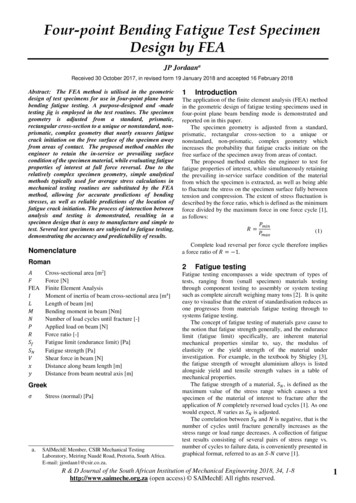
ILLINOIS ENGINEERING EXPERIMENT STATIONthe study of cast iron as a material, and (2) the study of the effectivestrength of the material in different parts of a casting. The secondproblem includes the effect of internal strains, minute cracks, varyingrate of cooling of different parts of the casting, inclusions of dirt andslag, and the form assumed by the flakes of graphite in the cast iron.Problem (1), the strength of cast iron as a material, may best be studiedby means of tests of specimens cut from castings of simple shape, castunder carefully controlled foundry conditions, since in such parts the castiron is most nearly uniform in quality and the effects of irregularities areleast. It is evident that the study of the effective strength of cast ironin different parts of complicated castings would be a much more difficultmatter.In this bulletin the test results may, in general, be considered ascontributions to the study of the strength of cast iron as a material,although one series of tests was made on specimens cut from the innerwall of a large iron cylinder with double walls.4. Foundry History of Cast Irons Tested.-Four different lots ofcast iron were tested, and they are hereafter referred to by the laboratorynumbers 91, 92, 93, and 94. The specimens of cast iron 91 were cut froma section of a 6-in. cast-iron pipe bought in the open market. Thispipe was made by a centrifugal casting process in horizontal sand molds.Figure 1 shows the location of specimens.Cast irons 92 and 93 were obtained from castings supplied by theAllis-Chalmers Manufacturing Company. The castings were in theform of hollow cylinders with a narrow flange at one end. Cast iron 92was from a cylinder having a wall approximately 1 in. thick, whose formand size are shown in Fig. 1; and cast iron 93 was from a cylinder havinga wall approximately 3 in. thick, whose form and size are also shown inFig. 1. Both these cylinders were cast in green sand molds having drysand cores.Cast iron 94 was from a piece cut from the inner wall of a doublewall cylinder casting. The general location of the slab from which specimens were cut and the location of specimens in the slab are shown inFig. 2.5. Chemical Composition and Metallographic Structure of CastIrons Tested.-The chemical composition of cast irons 91, 92, 93, 'and94 is given in Table 1. The analyses show no very marked differencesand are representative analyses for good gray cast iron.In Fig. 3 are presented micrographs of unetched samples of thecast irons tested. These show the distribution of the graphite flakes in
TESTS OF THE FATIGUE STRENGTH OF CAST IRONbi.'J IK
10ILLINOIS ENGINEERING EXPERIMENT STATIONf,z0zar/2F \\\\\\\7\\\\\\\7v\\v\\
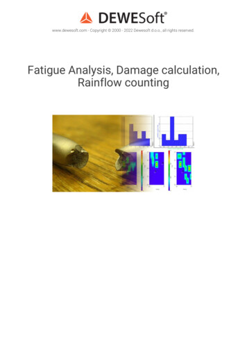
92FIG. 3. MICROGRAPHS OF UNETCHED CAST IRON (x75)
93-A93-BFIc. 3(CONTINUED).MICROGRAPHSOF UNETCHEDCAST IRON(x75)
94-AFIG. 3 (CONTINUED).MICROGRAPHS OF UNETCHEDCAST IRON(x75)
94-CFIG. 3 (CONCLUDED).MICROGRAPHS OF UNETCHED CAST IRON (x 75)
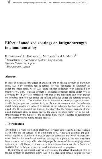
92FIG. 4.MICROGRAPHS OF ETCHED CAST IRONEtched with 5 per cent picric acid in alcohol.(x 750)
FIG. 4 (CONTINUED).93-BMICROGRAPHS OF ETCHED CAST IRON (x 750)Etched with 5 per cent picric acid in alcohol.
93-C.94-A.FIG. 4Etched witl5 per cent picic acidi in alcohol.Etched with 4 per cent nitric acid in alcohol.(CONTINUED).MICROGRAPHS OF ETCHED CAST IRON (x 750)
94-B94-CFIG. 4 (CONCLUDED).MICROGRAPHS OF ETCHED CAST IRON (xEtched with 4 per cent nitric acid in alcohol.750)
TESTS OF THE FATIGUE STRENGTH OF CAST IRONTABLE ICHEMICAL COMPOSITION OF CAST IRONS TESTEDContent, per centCast 0.0960.1020.1000.103Phosphorus 2.782.82. *. *CombinedCarbon0.840.680.550.570.43. *. ned carbon content was less than 0.05 per cent; nearly all the carbon was graphitic.the iron. A fairly extensive microscopic examination of specimens revealed no appreciable segregation of graphite.In Fig. 4 are presented micrographs of etched specimens takenat higher magnifications than those shown in Fig. 3. The micrographsof Fig. 4 indicate that for cast irons 91, 92, and 93 lamellar pearlite'isthe dominant crystalline constituent present. Scattered grains ofsteadite are discernible in this matrix of lamellar pearlite.Cast iron 94, which cooled more slowly due to the large mass of thecasting, contains its carbon almost entirely in the form of graphite.Ferrite is the dominant crystalline constituent in this case, with scatteredareas of pearlite usually grouped around occasional grains of steadite.The pearlite varies from the lamellar form to the globular, with thetransition stages in evidence.All the irons were tested as cast. No special heat treatment wasapplied either at the foundry or in the laboratory. Cast iron 91 wasallowed to cool in the mold instead of being shaken out while still hot,as is quite common practice for centrifugal-cast pipe.6. Test Specimens and Methods of Testing.-Test bars were cutfrom the pieces of iron furnished as shown in Figs. 1 and 2. Thesetest bars were then cut up into specimens for static tension tests, forCharpy notched-bar tests, for repeated impact tests, and for rotatingbeam fatigue tests. The form and size of the specimens used are shownin Fig. 5. It should be noted that since the thickness of the wall of thepipe from which the specimens of cast iron 91 were cut was only 12 in.it was necessary to make the tension specimen and the rotating-beamspecimen for this case slightly smaller than those shown in Fig. 5. Thetension specimens of cast iron 91 were made with a minimum diameter
12ILLINOIS ENGINEERING EXPERIMENT STATION- "-'--T-'3-1"472-,n.e S,,iei'o.a5cs/of5SadL-/--eay nforec'/ionChierpTe dThesas(ts-SmecaihnT7() n-Sn ec/rt earth -/"d//a,-\./i tes er"(d)Spec/me/ for Repea'fed-/iv'c/ 7T'st.-------------.Silg.{----(e)-Spec/me/? for Sfa'fi/c Co/7press/o/2 TestFIG. 5. TEST SPECIMENSof 0.3 in., and the rotating-beam specimens with a minimum diameterof 0.325 in. and a maximum diameter of 0.400 in.The tension tests were made on a 100 000-lb. three-screw Olsentesting machine. The tension specimens were specially designed to avoidstress-concentration near the critical section. They were held in Robertson shackles* shown in Fig. 6, which minimize any flexural action on the*See 1921 report of the British Aeronautical Research Committee.
TESTS OF THE FATIGUE STRENGTH OF CAST IRONFIG. 6.ROBERTSON SHACKLES FOR TENSION TEST SPECIMENSspecimen. In the case of cast iron 91 tests with specimens of the typeshown in Fig. 5b held in Robertson shackles gave a value for ultimatetensile strength about 12 per cent above that obtained for specimenshaving parallel sides and held in ordinary spherical-seated shackles.Charpy impact tests were made on a Sauveur and Boylston 30meter-kilogram testing machine. Repeated impact tests were made on aspecial double-hammer machine built in the shops of the Departmentof Theoretical and Applied Mechanics.Fatigue tests were made on Sondericker (or Farmer) type rotatingbeam testing machines. Brinnell tests were made on broken Charpyspecimens using an Alpha (Swedish) machine.The technique of testing, the methods of reducing test data, and amore detailed description of the testing machines used are given inBulletin 124 of the Engineering Experiment Station of the University ofIllinois.
ILLINOIS ENGINEERING EXPERIMENT STATIONTABLE 2TEST DATA OF ROTATING-BEAM FATIGUE TESTS OF CAST IRONSpeed of Testing Machines, 1500 r.p.m.Specimen No.Stress inlb. per sq. in.Cycles forRuptureCast Iron 9191-M-0 .91-C-0 .91-N-0.91-K-0 .91-1-0. .91-E-0 .91-G-0 97313230876100 799100 02629 113500300900300200100*200*800*Cast Iron 9292-2 .92-21.92-1.:.92-24.92-22 .92-3 .92-26 .92-20.92-60.92-23 00*900*Cast Iron 93A93-25-A.93-16-A.93- 9-A.93- 5-A.93-17-A.93-13-A.93-21-A 38422277943 058107 971113 082800900000800800900300*900*Cast Iron 93B93-25-B.93- 1-B.93-21-B.93-29-B .93- 5-B.93- 9-B.93-13-B.93-17-B.93-27-B.93-11-B.93- 0500600300900300*500**Specimen did not fail.20419615122165241Specimen No.SStress inlb. per sq. in.Cycles forRuptureCast Iron 93C93-17-C.93-27-C93- 4-C.93-13-C.93- 1-C.93- 090000000000038000050014943691414312031 410214 714102 168800100100300500300700000*800*Cast Iron 94A94-14-A.94-12-A.94- 4-A94- 6-A.94-13-A.94-10-A.94- 8-A.94- 9-A.94- 00*800*Cast Iron 94B94- 6-B.94-14-B.94-12-B .94-10-B.94- 4-B.94- 0603800900000600900*800*Cast Iron 94C94- 6-C.94-14-C.94-10-C.94- 8-C.94- 4-C.94-12-C.94- 5-C.94- 9-C.15 00011 0009 5009 0008 8008 5008 0007 0*3532050
TESTS OF THE FATIGUE STRENGTH OF CAST IRON
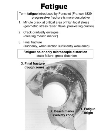
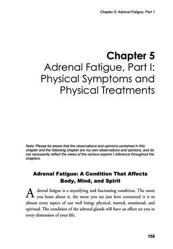
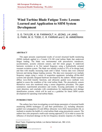
ILLINOIS ENGINEERINGt24NI000eo 0001z6\KEXPERIMENT STATIONH,.Ccarsf /ror -No.9/W0.91'P000//r.o9.92 o'3tNo. If-onPI---AlNv C 'st It-on.444060I.?. A-B-C4'7CNo.5t /A-0/A/,i ? A-B-iCCas/ /4-0/7//I: oo380006IB7, ---·L//if S/-rb. /nch/7e per /?ch/?FIG. 7.STRESS-STRAINDIAGRAMS FOR STATIC TENSION TESTSSee Table 3.III. GENERAL TEST DATA AND RESULTS7. Static Tension Tests and Brinell Tests.-The results of the statictension tests are given in Table 3 and typical stress-strain diagrams inFig. 7. No well-marked proportional elastic limit and no yield pointwere developed for any tension specimen. The elongation after fractureand the reduction of area for tension test specimens were too small tobe measured.Table 3 also gives the results of the Brinell hardness tests. In theBrinell tests a standard 10 millimeter ball was used, but the loadwas 1000 kilograms. The Brinell number for a given diameter of impression was taken as one-third that given in the U. S. Bureau of Standards reduction tables for a 3000-kilogram load.8. Charpy Notched-bar Tests.-Table 3 also gives the Charpynotched-bar values obtained. Each value reported is the average ofresults of tests on from four to six specimens. It will be noted that, asmight be expected, the Charpy values, with the exception of those forcast iron 92, are very low compared with those for steel. Charpy valuesfor normalized machine steel of 14 foot-pounds and for heat-treatedalloy steel of 45 foot-pounds are not unusual.9. Rotating-beam Fatigue Tests.-Table 2 gives the data of thefatigue tests, and Figs. 8, 9, and 10 the S-N diagrams obtained from
TESTS OF THE FATIGUE STRENGTH OF CAST IRON.18090016000ig/ohnj 14/0CAS ir--C as-A9/NoA.9/-Alroe/0 0- -----------20008--.---Fo/600014 000le 000ouCycles SA-929 Z--------c--/ 00008007/o 4 r/0st/aCyc/es for Rupl/ure-,FIG. 8./7/()S-N DIAGRAMS FOR CAST IRONS 91 AND 92them. Table 3 gives the endurance limits determined from the S-Ndiagrams, and also the ratio of endurance limit to ultimate tensilestrength-the endurance ratio.wt aaveeres 0.37, withe ratioiof averagesthetheenduranceendurtestedfro,iro"4thn iron testedFor thecastt verageof04Thisvalu91.hgironforcastof0.46high valuewith an average value of about 0.42 for cast steel* and an average valueof about 0.50 for wrought ferrous metals.tFor cast irons 93 and 94 specimens were cut from the middle of thethickness of the cast piece (B specimens) and also from near the surfaces(A and C specimens, Figs. 1 and 2). For cast iron 93 the specimens fromthe middle of the thickness showed a slightly lower endurance limitthan those from near the surface but the difference was not very marked.For cast iron 94 the metal from the middle of the thickness seemed tobe as strong as the average of the specimens from near the two surfaces.Cast iron 94 is a little lower in total carbon than the other castirons tested, but has about the same content of graphitic carbon. Assuggested on p. 11 it may be regarded as made up of ferrite crystallinegrains, a few scattered pearlite grains, and many flakes of graphite.Its static tensile strength, its Brinell hardness and its fatigue strengthEng. Exp. Sta. Bul. 156, p. 16.*Univ. of Ill.Eng. Exp. Sta. Bul. 136, Fig. 19, p. 53.tUniv. of Ill.
ILLINOIS ENGINEERING EXPERIMENT STATION18000/6 000 -3-ANCas /ron N.14000/2000-----/0000-I8000111If/VflI/0'IO"Cycles for Rupf1r/e, f(/VjI/4000- Cast Iron No. 93-B--/2000IZ Im 29IIi8000I -s'0/0Is--107II/08Cryc/es for Rupfure, W/) Cyc/es for Rupf/ure ([/VFIG. 9.S-N DIAGRAMS FOR CAST IRON 93are distinctly lower than those of cast irons 91, 92, and 93. As notedon p. 11 it seems probable that the slow cooling of the large casting,from which the test specimens of cast iron 94 were cut, accounts, in partat least, for the formation of the ferrite grains and the almost completegraphitization of the carbon, with resulting low strength.IV. SPECIAL TESTS10. Effect of "Understressing"* in Raising the Endurance Limit ofCast Iron.-Several experimenterst have shown that, for certain*"Understressing" consists in subjecting a test specimen to a large number of cycles of stressslightly below the endurance limit.tMoore, R. R., Proc. A.S.T.M., Vol. 24, part II, 1924, p. 565. Univ. of Ill., Eng. Exp. Sta. Bul.142, p. 27. Gillett and Mack, Proc. A.S.T.M., Vol. 24, part II, 1924, p. 490. Gough, H. J., "TheFatigue of Metals" (Scott, Greenwood & Son), p. 108. Smith, J. H., Jour. (British) Iron and SteelInst., 1910, part II, p. 280.
TESTS OF THE FATIGUE STRENGTH OF CAST IRON'"0 UL/U/rtv v/jfilmIICast /ro ,n No. 94-A C/2000/00001,'4D AAAnn--------- 0 6000--/OS/06E/0Cyc/es for1/upVA/ure,N10 UU-14 000----S%----12000S000----7(/V)-------010000Id-Y I-80001-70001---I/0 4/0/0-I/0671o 8Cyc/es for 9&uv/'re, (VA)16000------ /2 006-------------Cas/- /ro/7A/a 94-C-----------------/0000&0007 500/o04-/0/0SCY/c/esFIG. 10./0for7/8Ruptu0re, (/V)S-N DIAGRAMS FOR CAST IRON 94metals, if a fatigue specimen is subjected to a large number of cyclesof stress below the endurance limit of the virgin metal, followed by several series of large numbers of cycles with a slightly increased stress foreach successive series, the endurance limit may be raised considerablyabove that of the virgin metal. The largest recorded increase of which
ILLINOIS ENGINEERING EXPERIMENT STATIONthe authors have knowledge is 30 per cent for a 0.37 per cent carbonsteel.It has been commonly thought that this effect of understressingoccurred only for metals having a high ductility, as shown by elongationafter fracture and reduction of area. As a matter of interest a series ofunderstressing tests were made on specimens of cast irons 93 and 94 andthe results of these tests are given in Table 4.Most of the specimens so tested were first subjected to a run of atleast 100 000 000 cycles at a stress equal to or a little less than the endurance limit. After this the stress on the specimen was increased byapproximately 500 lb. per sq. in. and a further run of several millioncycles given before an addition of stress was made. The entire test wascontinuous; the testing machine was not stopped until fracture, or thefinal removal of an unbroken specimen. The increment of stress was thesame in all cases but the number of reversals at each stress was smallerin the case of specimen 93-29-C than in the others and the amountby which the endurance limit was raised was found to be less for thisspecimen. For the tests made, the greater the number of cycles at eachstress the greater was the strengthening effect. To see whether the verylong initial run of 100 000 000 cycles was a factor of great importance,specimen 93-14-A was given a much shorter initial run, and the resultseemed to indicate that a very long initial run was not necessary. Thebasis on which the percentage increases given in Table 4 have beencalculated is as follows: If, under the stress at which the specimenfinally fractured, the number of repetitions before fracture exceeded5 000 000, then the stress at fracture was considered as the new endurance limit; if the number was less than 5 000 000, then the average of thestress at fracture and the preceding stress was considered as the new endurance limit.It will be seen that in all cases the endurance limit is quite considerably increased, and in the case of specimen 94-5-A the amount ofincrease (43 per cent) is greater than that usually found with steel.It seems difficult to reconcile the present results with the theorypreviously put forward as an explanation of the strengthening effect ofreversed stresses. This theory considers understressing as analogousto "cold work." Certain kinds of cold work increase the static andfatigue strength of metals, and the theory regards the action of repeated stresses of an amount insufficient to cause fracture as producingbeneficial cold-work conditions, over a small area. The action of reversed stress upon the static properties of a material confirms this view.Experiments* on steel have shown an increase in static ultimate tensile*Univ. of Ill. Eng. Exp. Sta. Bul. 142, p. 21.
TESTS OF THE FATIGUE STRENGTH OF CAST IRONTABLE 4TEST DATA OF UNDERSTRESSING* TESTS ON CAST IRONSpecimen93.21 A.93.29 A .93 A .93.29 C .93.8 B .94.5 A .94.4 B .OriginalEnduranceLimit ofMetallb. per sq. in.10 00010 00010 00010 0009 0007 0007 200Unit-stress(rotatingbeam)Number ofCycles ofStresslb. per sq. 01023135000 000700 000000 000560 000630 000610 000000 000456 000failed99101010111112000500000400900400800300113 000 0006 078 00013 080 00010 800 0008 800 00026 061 00013 250 00015 400 101215147680 000790 000450 000110 000700 000143 000failed991010111140090040080030080010264444170 000057 000310 000515 000273 000094 10112025 000900 000310 000205 700163 000183 000096 3773 000673 000274 000014 000500 000930 000724 000failed77889200700100600100511015121441 000956 000584 000887 000103 000failedEnduranceLimit afterUnderstressinglb. per sq. in.Increase overOriginalEnduranceLimit 4per cent13 30033not less than12 300not less'than2312 2002211 6001611 6002810 000438 80022*"Understressing" consists in subjecting a test specimen to a large number of cycles of stressslightly below the endurance limit.
ILLINOIS ENGINEERING EXPERIMENT STATIONstrength and a decrease in ductility (as measured by percentage reduction of area), after the material has been subjected to many millionsof repetitions of a stress almost equal to the endurance limit. This isexactly the effect of static cold work, and the indication is, therefore,that understressing is a form of cold work. However, it should be notedthat static cold work may be produced by static compression as well asby drawing and rolling. In fact, in commercial cold-rolling and colddrawing the metal is subjected to heavy compression, which may bethe source of the increased strength. The theory mentioned furtherexplains the actual strengthening action of understressing on the groundsthat at low stresses slip takes place, and if this slip is not accompaniedby the formation of a crack, its effect is to readjust the particles in sucha manner that they are better able to resist further slip.* It would seem,therefore, that the more the material is able to stand permanent
4. Test Data of Understressing Tests on Cast Iron . . . . . . . 21 5. Test Data of Understressing Tests on Annealed Brass . . . . . . 23 6. Tensile Test Results for Specimens of Cast Iron Subjected to Understressing 25 7. Test Data of Fatigue Tests (Rotating-beam) of Cast-Iron Specimens with