Transcription
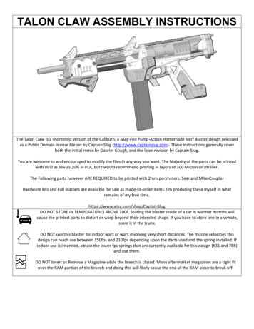
TALON CLAW ASSEMBLY INSTRUCTIONSThe Talon Claw is a shortened version of the Caliburn, a Mag-Fed Pump-Action Homemade Nerf Blaster design releasedas a Public Domain license file set by Captain Slug (http://www.captainslug.com). These instructions generally coverboth the initial remix by Gabriel Gough, and the later revision by Captain Slug.You are welcome to and encouraged to modify the files in any way you want. The Majority of the parts can be printedwith infill as low as 20% in PLA, but I would recommend printing in layers of 300 Micron or smaller.The Following parts however ARE REQUIRED to be printed with 2mm perimeters: Sear and MilanCouplerHardware kits and Full Blasters are available for sale as made-to-order items. I'm producing these myself in whatremains of my free time.https://www.etsy.com/shop/CaptainSlugDO NOT STORE IN TEMPERATURES ABOVE 100F. Storing the blaster inside of a car in warmer months willcause the printed parts to distort or warp beyond their intended shape. If you have to store one in a vehicle,store it in the trunk.DO NOT use this blaster for indoor wars or wars involving very short distances. The muzzle velocities thisdesign can reach are between 150fps and 210fps depending upon the darts used and the spring installed. Ifindoor use is intended, obtain the lower fps springs that are currently available for this design (K31 and 788)and use them.DO NOT Insert or Remove a Magazine while the breech is closed. Many aftermarket magazines are a tight fitover the RAM portion of the breech and doing this will likely cause the end of the RAM piece to break off.
For most of the above hardware list the quantities are the MINIMUM required for assembly. Easily-lost items will haveseveral spares and I typically include extras of the majority of the items.To assemble this blaster you will need a Slotted Screwdriver, Small Philips Screwdriver, 3/8 Combination Wrench, and aRound Needle File. You may also need a 3/16” drill bit and a SLOW power drill.The Plunger Tube in the Hardware Kit does come pre-lubricated. But it's also a good idea to have extra lubricant on-handfor the Plunger Tube and I would recommend only using a clear Silicone Grease such as Oatey's brand #30219. Any clear90% silicone grease will work fine so long as it does not include any additives. NEVER USE SILICONE LUBRICANT FROMAN AEROSOL CAN. The propellants used in those are harmful to plastic parts.ALSO AVOID DRY-FIRING THIS BLASTER EXCESSIVELY. Firing without a dart in the barrel will add unneeded wear on thisblaster, especially if the higher load rating springs are installed. Also do not pull the trigger with the foregrip in therearward position (with the breech open). The breech being slammed closed by the main spring is very likely to damageboth the breech itself and the magwell.
Above is a list of every printed part needed to assemble this blaster. The majority of the through holes should print tothe required tolerance, but you will likely have one or two that may require minimal filing. Also make sure to trim off anyburrs or oversized edges.Add an extension spring to the peg on SEAR and use SEAR to fish the extension spring into the grip. Push the loop of the
extension spring onto the hook inside of the grip.Insert the 4-40 standoff into the center hole of the SEAR and pivot it down towards the back of the grip.Use two short 4-40 screws to secure the standoff to the back of the grip.
Fish the TRIGGER in through the front of the grip. You may need to pivot the SEAR back in order to get the TRIGGER inplace. Once in place, the bump on the back of TRIGGER needs to sit underneath the front lip of the SEAR.Slide a Short Pin in through the side of the grip and through the hole in the TRIGGER. You may need to use a 1/16" drillbit or another Short Pin and a hammer to lightly tap it through the trigger.
You can use a 4-40 short screw on each side of the grip to retain the Short Pin for the trigger.Slide the Tguard piece into the slot in the front of the Grip.If Tguard7 and Grip5t were the parts printed, drive a 4-40 screw in from each side to secure the parts together.For the older file revisions insert another short pin into the grip and through the TGUARD piece to secure it. Tap it intoplace lightly with a hammer if needed. If the fit was too loose, apply from super glue and set it aside to dry.
Check the hole in TRelease and KRelease parts for obstructions or burrs and remove them if present. Line up the hole inthem with the indicated hole in the LowerMag. Insert a Short Pin through the Magwell and into TRelease and KRelease.You can use an extra Short Pin and a Hammer to push it into place. Use a 4-40 screw and a screwdriver to plug the openhole. Repeat for the opposite side of the LowerMag.Make sure that the TRelease and KRelease can both rotate freely on the Short Pin. If they cannot, back one of the 4-40screws out a little until they do. Hook one end of an extension spring onto the printed arm inside the back of theLowerMag. Hook the opposite end of the extension spring onto the peg on the TRelease. Repeat for KRelease.
Slide the Milan Coupler onto the back of the LowerMag. Check the fit of a TakeDown pin in the holes for both. If it won’tgo through, clean out the hole with a 3/16” drill bit. Make sure to drill all of the way through.Drive the takedown pin in through both parts by hand. It should not be a loose fit, but it also should not require ahammer to be installed.Insert a hex nut into each of the three slots in the Milan Coupler.Screw 9.3-inch length threaded rods into the hex nuts from the holes back of the Milan Coupler.Once installed the upper threaded rod should be sticking out roughly half of an inch.The lower two should not stick out any further than the inside corner of the sides of the Milan Coupler.
Slide the Rail piece onto the upper threaded rod from the back. Slide the Grip assembly onto the lower threaded rods.Depress the trigger to get the Sear out of the way. Feed the Plunger tube into the back of the assembly and into theMilanCoupler until flush with the front face of it.
Nest a hex nut in the socket inside the slot of the Kiri print.Add a hex nuts to each threaded rod and tighten by hand. Check that the front end of the plunger tube is still flush orrecessed within the front face of the MilanCoupler and that the hex nuts at the front end of the threaded rods are stillnested into the hex slots.
The Rear Assembly is now complete.Use a Needle File to clean out the two lower holes at the front of the UpperMag. Also use it to clean any loose strandsfrom the inside of the hex nut slots. Then slide a hex nut into each slot. Add a third to the upper socket.
Screw three 9.3” threaded rods into the hex nuts from the holes at the front of the UpperMag. The lower two willbottom out against the inside of the part. Screw the upper threaded rod in until its screwed into the upper hex nut.Insert the barrel into the front of the UpperMag.Insert a hex nut into the socket inside the print.Drive a short 10-32 screw into the hex nut from the underside of the print until it is flush with the opposite side of thehex nut.
Slide the Front Grip over the Threaded RodsSlide the two Nylon Spacer Tubing lengths over the lower Threaded RodsThen slide the Front Rail print over the barrel and upper threaded rod. Then Slide the Muzzle onto the end of the Barrel.Slide two 11-1/4” long nylon spacers over the two lower threaded rods. If the Barrel Shroud segments are not beingused, slide a third nylon spacer over the upper threaded rod.Slide the Muzzle onto the barrel and threaded rods until it bottoms out against all three spacers.Add a hex nut to the end of each threaded rod and tighten them.Tighten the screw in the bottom of the muzzle print until it clamps down on the barrel.
While assembling the front half and tightening the hex nuts from the front, look in through the back of the uppermagwell. Make adjustments to the hex nuts until the barrel is lined up and concentric with the magwell like what isshown above.If it is present, add a 012 o-ring to the undercut in the ram.Secure the Bolt Arms to the ramrod with two 4-40 screws. DO NOT OVERTIGHTENAdd a 123 o-ring to the rear undercut of the Ramrod. Then remove the backing paper from the Shockpad and adhere itto the back of the Ramrod.
Slide the Bolt Assembly forward through the slots in the magwell. Deburr the indicated edges if they are impedingmovement of the bolt arms.Slide the Foregrip back over the aluminum straps (Bolt Arms) until the threaded holes line up with the holes in theForegrip. Secure them together at the rear pair of holes using two short 10-32 screws. Secure the front half of theForegrip with two more short 10-32 screws.Then slide the Foregrip forward and make sure the the Ramrod is entering the Barrel during this action. If it isn’t doingso smoothly double-check its alignment and try again.
Slide TrenchC onto the end of the barrel until it encapsulates all three hex nuts. Use a 4-40 screw to attach the TrenchCto Muzzle5c. The assembly of the Front-Half of the Elite blaster is now complete.Add a 123 O-Ring to the Plunger then slide it into the plunger tube from the front.Slide the Front-Half onto the EliteLower from above. Use the foregrip to push the base of the Ramrod into the Plunger
Tube. You may need to push the o-ring into the plunger tube in one or two spots if it gets stuck. Slide the Front-Halfassembly back onto the threaded rod ends and bottom it out against the MilanCoupler.Push a Takedown pin into through the top of the UpperMag and through the Tabs of the Milan Coupler. The heads ofthe pins should bottom out into the UpperMag.If the pins do not want to insert all the way, you may need to touch up the holes in all of the associated parts with a3/16” drill bit run SLOWLY with a power drill, or by hand, or with a small round needle file.Use a 3/8” Combination wrench to tighten the hex nuts at the back of the stock. Look down the top of the blaster andconfirm that the assembly is straight. Adjust the tightness of the hex nuts until the entire blaster is straight.Align all of the hex nuts so their sides are parallel with each other and the sides of the Butt2Kiri piece.Slide a Main Spring of your choice in through the back of the Stock.
Slide the ButtCap print onto the end of the threaded rods until it encapsulates all three hex nuts. Add a hex nut to theupper threaded rod to secure it.Feed a 1-3/4” length screw in through the assembly and screw it into the lower captive hex nut until tight.Slide the foregrip back to compress the mainspring until the plunger gets engaged on the Sear.With the breech OPEN install a Magazine loaded with darts. Slide the foregrip all the way forwards to chamber the dartin the top of the Magazine. You can load up to four darts into the barrel at a time if desired by cycling the Foregrip backand forth multiple times prior to pulling the Trigger. ONLY PULL THE TRIGGER WHEN THE BREECH IS CLOSED AND THEFOREGRIP IS IN THE FORWARD POSITION. If you do not have a dart loaded in the barrel and need to pull the Trigger tode-prime the blaster, plug the end of the barrel with your finger before doing so.Replacing the Main Springdoes not require full disassembly of the Blaster. You just need to reverse the last 2 steps inthese instructions in order totake the buttplate off.The Blaster and Hardware Kits are shipped with K26 and K25 springs. The K25 is rated slightly lower than the K26. Thealternate spring options are the K31 and 788 which both have to be purchased separately or opted for as a replacement.Either are recommended for indoor use, or for younger players.To reduce the performance of the Blaster by 10% to 20% the Ram can be operated with the O-Ring removed/absentwithout any issues.
ADDENDUM: Installation of AccessoriesSlide the Angled Foregrip part onto the lower rail of the FrontGrip.Line of the Core print with the rail segments of the FrontGrip through the window in the side of the Angle Foregrip. Usea hammer to tap the Core piece into the AFG part until centered.Insert a hex nut into the socket in the front of the Gripstrike print. Slide the Gripstrike into the bottom of theGrip/Handle until snug. Align the holes in Gripstrike with the hole in the heel of the Grip/Handle.Attach the two by feeding a 1-3/4” length screw into the hole in the Grip/Handle until it meets the hex nut. Tighten untilthe screw bottoms out and clamps the two parts together.
TALON CLAW ASSEMBLY INSTRUCTIONS The Talon Claw is a shortened version of the Caliburn, a Mag-Fed Pump-Action Homemade Nerf Blaster design released