Transcription
COATING BACKGROUNDER. T-3CoatingBackgrounderTECHNICAL GUIDECOATING TRACES. T-25OPTICAL SPECIFICATIONS. T-59Coating TracesMATERIAL PROPERTIES. T-43Material PropertiesOptical Specificationscvilaseroptics.comT-1
Optical CoatingsCoatingBackgrounderand Materialscvilaseroptics.comT-2
OPTICAL COATINGS T-4CoatingBackgrounderCOATING BACKGROUNDERTHE REFLECTION OF LIGHT T-5MULTILAYER ANTI-REFLECTION COATINGS T-15HIGH REFLECTION COATINGS T-18Coating TracesSINGLE-LAYER ANTI-REFLECTION COATINGS T-10LASER-INDUCED DAMAGE T-23OEM AND SPECIAL COATINGS T-24Material PropertiesOptical Specificationscvilaseroptics.comT-3
OPTICAL COATINGSOptical CoatingsCoatingBackgrounderand MaterialsThe vast majority of optical components are made ofvarious types of glass, and most are coated with thinlayers of special materials. The purpose of these coatingsis to modify the reflection and transmission properties ofthe components’ surfaces.Whenever light passes from one medium into a mediumwith different optical properties (most notably refractiveindex), part of the light is reflected and part of the lightis transmitted. The intensity ratio of the reflected andtransmitted light is primarily a function of the change inrefractive index between the two media, and the angle ofincidence of the light at the interface. For most uncoatedoptical glasses, 4-5% of incident light is reflected ateach surface. Consequently, for designs using morethan a few components, transmitted light losses can besignificant. More important are the corresponding lossesin image contrast and lens resolution caused by reflectedghost images (usually defocused) superimposed on thedesired image. Applications generally require that thereflected portion of incident light approach zero fortransmitting optics (lenses), 100% for reflective optics(mirrors), or some fixed intermediate value for partialreflectors (beamsplitters). The only suitable applicationsfor uncoated optics are those where only a few opticalcomponents are in the optical path, and significanttransmission inefficiencies can be tolerated.In principle, the surface of any optical element canbe coated with thin layers of various materials (calledthin films) in order to achieve the desired reflection/transmission ratio. With the exception of simple metalliccoatings, this ratio depends on the nature of the materialfrom which the optic is fabricated, the wavelength of theincident light, and the angle of incidence of the light(measured from the normal). There is also polarizationdependence to the reflection/transmission ratio whenthe angle of incidence is not normal to the surface.A multilayer coating, sometimes made up of more than100 individual fractional-wavelength layers, may be usedto optimize the reflection/transmission ratio for a specificwavelength and angle of incidence or to optimize it overa specific range of conditions.index glasses that are soft or prone to staining can beprotected with a durable antireflection coating. Severalfactors influence coating durability. Coating designsshould be optimized to minimize thickness and reducemechanical stresses that may distort the optical surfacesor cause detrimental polarization effects. Resilientmaterial must used. Great care must be taken in coatingfabrication to produce high-quality, nongranular, evenlayers.CVI Laser Optics is a leading supplier of precision opticalcomponents and multielement optical systems. Wehave achieved our market-leading position by having anextensive knowledge of the physics of thin-film coatingsand without the advanced production systems andmethods required to apply such coatings in production.With state-of-the-art coating facilities CVI Laser Opticsnot only is able to coat large volumes of standardcatalog and custom optical components, but also is ableto develop and evaluate advanced new coatings forcustomers’ special requirements.Although our optical-coating engineers and technicianshave many years of experience in designing andfabricating various types of dielectric and metalliccoatings, the science of thin films continues to evolve.CVI Laser Optics continually monitors and incorporatesnew technology and equipment to be able to offer ourcustomers the most advanced coatings available.The CVI Laser Optics range of coatings currentlyincludes antireflection coatings, metallic reflectors, alldielectric reflectors, hybrid reflectors, partial reflectors(beamsplitters), and filters for monochromatic, dichroic,and broadband applications.With new and expandedcoating capabilities, including the new deep-UVoptimized Leybold SYRUSpro 1100 , CVI Laser Opticsoffers the same high-quality coatings to customers whowish to supply their own substrates. As with any specialor OEM order, please contact CVI Laser Optics to discussyour requirements with one of our qualified applicationsengineers.Today’s multilayer dielectric coatings are remarkablyhard and durable. With proper care and handling, theycan have a long life. In fact, the surfaces of many high-T-4cvilaseroptics.com
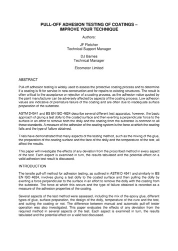
CoatingBackgrounderTHE REFLECTION AND REFRACTION OF LIGHTREFLECTIONS AT UNCOATEDSURFACESlight, as a proportion of the incident light, is given byWhenever light is incident on the boundary between twomedia, some light is reflected and some is transmittedinto the second medium, undergoing refraction. Severalphysical laws govern the direction, phase, and relativeamplitude of the reflected light. For our purposes,it is necessary to consider only polished opticalsurfaces. Diffuse reflections from rough surfaces are notconsidered in this discussion.(1 p )(1 p )When a beam of light is incident on a plane surface atnormal incidence, the relative amplitude of the reflectedLQFLGHQWUD\UHIOHFWHGUD\L LDLU UUn JODVV n WUHIUDFWHGUD\VLQVLQWLn DLUn JODVVINCIDENCE ANGLEThe intensity of reflected and transmitted beams ata surface is also a function of the angle of incidence.Because of refraction effects, it is necessary todifferentiate between external reflections, where theincident beam originates in the medium with a lowerrefractive index (e.g., air in the case of an air to glass orair to water interface), and external reflection, where thebeam originates in the medium with a higher refractiveindex (e.g., glass in the case of a glass to air interface, orflint glass in the case of a flint to crown-glass interface),and to consider them separately.EXTERNAL REFLECTION AT ADIELECTRIC BOUNDARYFresnel’s laws of reflection precisely describe amplitudeand phase relationships between reflected and incidentlight at a boundary between two dielectric media.It is convenient to think of the incident radiation asthe superposition of two plane-polarized beams, onewith its electric field parallel to the plane of incidence(p-polarized), and the other with its electric fieldperpendicular to the plane of incidence (s-polarized).Fresnel’s laws can be summarized in the following twoequations, which give the reflectance of the s- andp-polarized components:Figure 1.1 Reflection and refraction at a simple air to glassinterfacecvilaseroptics.comT-5Optical SpecificationsAt a simple interface between two dielectric materials,the amplitude of reflected light is a function of theratio of the refractive index of the two materials, thepolarization of the incident light, and the angle ofincidence.The greater the disparity between the two refractiveindexes, the greater the reflection. For an air to glassinterface, with glass having a refractive index of 1.5,the intensity of the reflected light will be 4% of theincident light. For an optical system containing tensuch surfaces, the transmitted beam will be attenuatedto approximately 66% of the incident beam due toreflection losses alone, emphasizing the importance ofantireflection coatings to system performance.Material PropertiesINTENSITYwhere p is the ratio of the refractive indexes of the twomaterials (n1/n2). Intensity is the square of this expression.Coating TracesThe law of reflection states that the angle of incidence(θ1) equals the angle of reflection (θr). This is illustratedin figure 1.1, which shows reflection of a light ray at asimple air to glass interface. The incident and reflectedrays make an equal angle with respect to the axisperpendicular to the interface between the two media. (1.1)
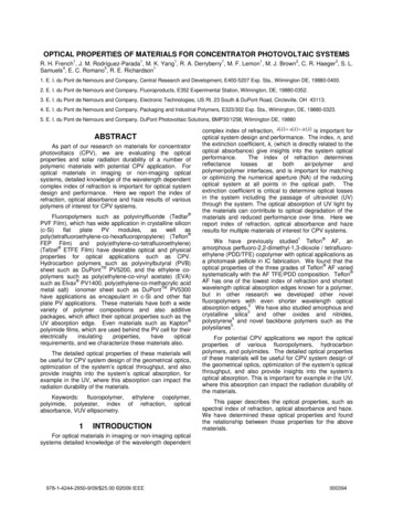
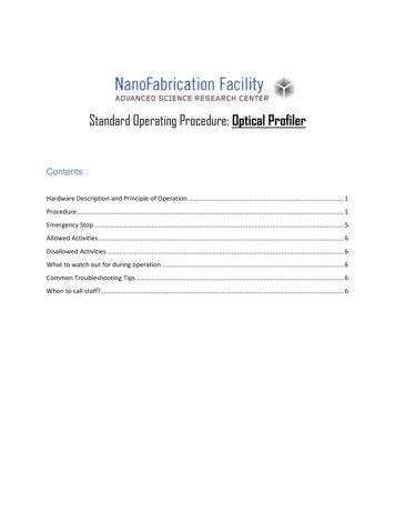
3HUFHQW 5HIOHFWDQFHOptical CoatingsCoatingBackgrounderand Materialsnote that the p-component vanishes at 56 .This angle, called Brewster’s angle, is the angle atwhich the reflected light is completely polarized. Thissituation occurs when the reflected and refracted raysare perpendicular to each other (θ1 θ2 90º), as shown infigure 1.3. This leads to the expression for Brewster’s angle, θB: θ1 θB arctan (n2 / n1 ) (1.5)S QJOH RI ,QFLGHQFH LQ 'HJUHHVFigure 1.2 External reflection at a glass surface (n 1.52)showing s- and p-polarized components sin (v v ) 2 (1.2)rs sin (v11 v 22 ) rs sin (v1 v 2 ) sin (v1 v 2 ) 2 tan (v1 v 2 ) 2rp tan (v1 v 2 ) (1.3).rp tan (v1 v 2 ) . tan (v1 v 2 ) 2In the limit of normal incidence in air, Fresnel’s lawsreduce to the following simple equation:2 n 1 r . n 1 (1.4)Under these conditions, electric dipole oscillations of thep-component will be along the direction of propagationand therefore cannot contribute to the reflected ray.At Brewster’s angle, reflectance of the s-component isabout 15%.S SRODUL]HGDEVHQW S SRODUL]HGUHIOHFWHG UD\QRUPDOLQFLGHQW UD\v1v1DLU RU YDFXXPLQGH[ Q 1LVRWURSLF GLHOHFWULF VROLGLQGH[ Q 2LV D[ROH RQSLLWGHFGLUUHIUDFWHG UD\GLSROH UDGLDWLRQSDWWHUQ VLQ2vv2S SRODUL]HGUHIUDFWHG UD\It can easily be seen that, for a refractive index of1.52 (crown glass), this gives a reflectance of 4%. Thisimportant result reaffirms that, in general, 4% of allillumination incident normal to an air-glass surface willbe reflected. The variation of reflectance with angle ofincidence for both the s- and p-polarized components,plotted using the formulas above, is shown in figure 1.2.Figure 1.3 Brewster’s angle: at this angle, the p-polarizedcomponent is completely absent in the reflected rayDvF FULWLFDO DQJOHIt can be seen that the reflectance remains close to 4%up to about 25º angle of incidence, and that it risesrapidly to nearly 100% at grazing incidence. In addition,EQ DLUFQ JODVVvFGGFFEDDEFigure 1.4 Internal reflection at a glass surface (n 1.52)showing s- and p-polarized componentsT-6cvilaseroptics.com
3HUFHQW 5HIOHFWDQFHQuantum theory shows us that light has wave/particleduality. In most classical optics experiments, the waveproperties generally are most important. With theexception of certain laser systems and electro-opticdevices, the transmission properties of light through anoptical system can be well predicted and rationalized bywave theory.&ULWLFDO DQJOH ,QWHUQDO QJOH RI ,QFLGHQFH LQ 'HJUHHVINTERNAL REFLECTION AT DIELECTRICBOUNDARYOptical SpecificationsFor light incident from a higher to a lower refractiveindex medium, we can apply the results of Fresnel’s lawsin exactly the same way. The angle in the high-indexmaterial at which polarization occurs is smaller by theratio of the refractive indices in accordance with Snell’slaw. The internal polarizing angle is 33 21' for a refractiveindex of 1.52, corresponding to the Brewster angle (56 39') in the external medium, as shown in figure 1.4.Light waves that are exactly out of phase with oneanother (by 180º or π radians) undergo destructiveinterference, and, as shown in the figure, their amplitudescancel. In intermediate cases, total amplitude is given bythe vector resultant, and intensity is given by the squareof amplitude.&RQVWUXFWLYH LQWHUIHUHQFHZDYH , PSOLWXGHZDYH ,,The angle at which the emerging refracted ray is atgrazing incidence is called the critical angle (see figure1.5). For an external medium of air or vacuum (n 1), thecritical angle is given byUHVXOWDQWZDYH7LPHGHVWUXFWLYH LQWHUIHUHQFH (1.6)ZDYH ,ZDYH ,, PSOLWXGHand depends on the refractive index nλ, which is afunction of wavelength. For all angles of incidence higherthan the critical angle, total internal reflection occurs.]HUR DPSOLWXGHPHASE CHANGES ON REFLECTIONThere is another, more subtle difference between internaland external reflections. During external reflection, lightwaves undergo a 180º phase shift. No such phase shiftoccurs for internal reflection (except in total internalreflection). This is one of the important principles onwhich multilayer films operate.cvilaseroptics.comMaterial PropertiesFigure 1.5 Critical angle: at this angle, the emerging ray is atgrazing incidenceOne consequence of the wave properties of light isthat waves exhibit interference effects. Light waves thatare in phase with one another undergo constructiveinterference, as shown in figure 1.6.Coating Traces INTERFERENCE7RWDO UHIOHFWLRQUS CoatingBackgrounder %UHZVWHU V DQJOH UV UHVXOWDQWZDYH7LPHFigure 1.6 A simple representation of constructive anddestructive wave interferenceT-7
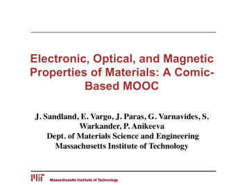
Optical CoatingsCoatingBackgrounderand MaterialsVarious experiments and instruments demonstrate lightinterference phenomena. Some interference effects arepossible only with coherent sources (i.e., lasers), butmany are produced by incoherent light. Three of thebest-known demonstrations of visible light interferenceare Young’s slits experiment, Newton’s rings, and theFabry-Perot interferometer. These are described in mostelementary optics and physics texts.In all of these demonstrations, light from a source issplit in some way to produce two sets of wavefronts.These wavefronts are recombined with a variable pathdifference between them. Whenever the path differenceis an integral number of half wavelengths, and thewavefronts are of equal intensity, the wavefronts cancelby destructive interference (i.e., an intensity minimumis produced). An intensity minimum is still produced ifthe interfering wavefronts are of differing amplitude, theresult is just non-zero. When the path difference is anintegral number of wavelengths, the wavefront intensitiessum by constructive interference, and an intensitymaximum is produced.THIN-FILM INTERFERENCEThin-film coatings may also rely on the principles ofinterference. Thin films are dielectric or metallic materialswhose thickness is comparable to, or less than, thewavelength of light.CVI Laser Optics offers a variety of single- and multilayerantireflection and high-reflection coatingsWhen a beam of light is incident on a thin film, someof the light will be reflected at the front surface, andsome light will be reflected at the rear surface, as shownin figure 1.7. The remainder will be transmitted. At thisstage, we shall ignore multiple reflections and materialabsorption effects.element of interest). In other words, the optical thicknessof a piece of material is the thickness of that materialcorrected for the apparent change of wavelength passingthrough it.The optical thickness is given by top tn, where t is thephysical thickness, and n is the ratio of the speed of lightin the material to the speed of light in vacuum:n cvacuum.cmedium (1.7)To a very good approximation, n is the refractive index ofthe material.Returning to the thin film at normal incidence, thephase difference between the external and internalreflected wavefronts is given by (top/λ)x2π, where λ is thewavelength of light. Clearly, if the wavelength of theincident light and the thickness of the film are such thata phase difference of π exists between reflections, thereflected wavefronts interfere destructively and overallreflected intensity is a minimum. If the two interferingreflections are of equal amplitude, the amplitude (andhence intensity) minimum will be zero.In the absence of absorption or scatter, the principleof conservation of energy indicates that all “lost”reflected intensity will appear as enhanced intensity inthe transmitted beam. The sum of the reflected andtransmitted beam intensities is always equal to theincident intensity.Conversely, when the total phase shift between tworeflected wavefronts is equal to zero (or multiples of 2π),then the reflected intensity will be a maximum, and thetransmitted beam will be reduced accordingly.The two reflected wavefronts can interfere with eachother. The degree of interference will depend on theoptical thickness of the material and the wavelength ofthe incident light (see figure 1.8). The optical thickness ofan element is defined as the equivalent vacuum thickness(i.e., the distance that light would travel in vacuum in thesame amount of time as it takes to traverse the opticalT-8cvilaseroptics.com
CoatingBackgroundern DLU Q GHQVH PHGLXPn a ln IURQW DQG EDFNVXUIDFH UHIOHFWLRQVlnt l n ltRS tn lKRPRJHQHRXVWKLQILOPCoating TracesDLU n a lWUDQVPLWWHG OLJKWtt RSUHIUDFWLYHLQGH[ QRSWLFDO WKLFNQHVVRI ILOP W RS QWWSK\VLFDOWKLFNQHVVFigure 1.7 Front and back surface reflections for a thin film atnear-normal incidenceFigure 1.8 A schematic diagram showing the effects of lowerlight velocity in a dense medium (in this example, the velocity of light is halved in the dense medium n n/n0, and theoptical thickness of the medium is 2 x the real thickness)Material PropertiesRSWLFDO WKLFNQHVVOptical Specificationscvilaseroptics.comT-9
SINGLE-LAYER ANTIREFLECTION COATINGSOptical CoatingsCoatingBackgrounderand MaterialsThe basic principles of single-layer antireflectioncoatings should now be clear. Ignoring scattering andabsorption,transmitted energy incident energy–reflected energy.If the substrate (glass, quartz, etc.) is coated with a thinlayer (film) of material, and if the reflections from theair/film interface and from the film/substrate interfaceare of equal magnitude and 180º (π radians) out ofphase, then the reflected waves will cancel each otherout by destructive interference, and the intensity ofthe transmitted beam will approach the intensity of theincident beam.FILM THICKNESSTo eliminate reflections at a specific wavelength, theoptical thickness of a single-layer antireflection filmmust be an odd number of quarter wavelengths. Thisrequirement is illustrated in figure 1.9. The reflectionsat both the air/film and film/substrate interfaces are“internal” (low index to high index) and the phasechanges caused by the reflections themselves cancelout. Consequently, the net phase difference between thetwo reflected beams is determined solely by their opticalpath difference 2tnc, where t is the physical thickness andnc is the refractive index of the coating layer. For a 180ºphase shift, 2tnc Nλ/2 and tnc Nλ/4 where N 1, 3, 5 . . .Single-layer antireflection coatings are generallydeposited with a thickness of λ/4, where λ is the desiredwavelength for peak performance. The phase shift is 180º(π radians), and the reflections are in a condition of exactdestructive interference.REFRACTIVE INDEXThe intensity of the reflected beam from a single surface,at normal incidence, is given by2 1 p 1 p the incident intensity (1.8)where p is the ratio of the refractive indexes of the twomaterials at the interface.For the two reflected beams to be equal in intensity, it isnecessary that p, the refractive index ratio, be the sameat both the interfacesnairnfilm. nfilm nsubstrate (1.9)Since the refractive index of air is 1.0, the thinantireflection film ideally should have a refractive index ofnfilm nsubstrate (1.10).DLUn WKLQILOPnJODVVn ,I tRS WKH RSWLFDOWKLFNQHVV nt l WKHQ UHIOHFWLRQVLQWHUIHUH GHVWUXFWLYHO\ZDYHOHQJWK lUHVXOWDQW UHIOHFWHGLQWHQVLW\ ]HURtSK\VLFDOWKLFNQHVVOptical glasses typically have refractive indexes between1.5 and 1.75. Unfortunately, there is no ideal materialthat can be deposited in durable thin layers with a lowenough refractive index to satisfy this requirementexactly (n 1.23 for the optimal antireflection coating oncrown glass). However, magnesium fluoride (MgF2) is agood compromise because it forms high quality, stablefilms and has a reasonably low refractive index (1.38) andlow absorbance at a wavelength of 550 nm.Magnesium fluoride is probably the most widely usedthin-film material for optical coatings. Although itsperformance is not outstanding for all applications, itrepresents a significant improvement over an uncoatedsurface. At normal incidence, typical crown glass surfacesFigure 1.9 Schematic representation of a single-layer antireflection coatingT-10cvilaseroptics.com
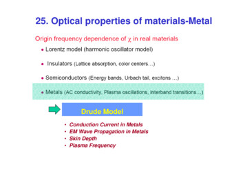
CoatingBackgrounderv DQJOH RI LQFLGHQFHvJODVV VLQJOH OD\HU0J ) Material Properties QJOH RI ,QFLGHQFH LQ LU ,Q 'HJUHHVOptical Specifications XQFRDWHG JODVV 0J ) ZDYHOHQJWK RSWLFDO WKLFNQHVVDW QP n Coating Traces3HUFHQW 5HIOHFWDQFH DW QP VXEVFULSWV R V UHIOHFWDQFH IRU s SRODUL]DWLRQ R DY UHIOHFWDQFH IRU DYHUDJH SRODUL]DWLRQ R S UHIOHFWDQFH IRU p SRODUL]DWLRQ3HUFHQW 5HIOHFWDQFHDW LQFLGHQFHR V QRUPDO LQFLGHQFH FRDWLQJ DW R V LQFLGHQFH FRDWLQJ R DY QRUPDO LQFLGHQFH FRDWLQJ DW R DY LQFLGHQFH FRDWLQJR S QRUPDO LQFLGHQFH FRDWLQJ DW R S LQFLGHQFH FRDWLQJ :DYHOHQJWK QPFigure 1.10 MgF2 performance at 45 incidence on BK7 for a normal-incidence coating design and for a coating designed for 45 incidence (design wavelength: 550 nm)cvilaseroptics.comT-11
Optical CoatingsCoatingBackgrounderand Materialsreflect from 4 to 5% of visible light. A high-qualityMgF2 coating can reduce this value to 1.5%. For manyapplications this improvement is sufficient, and higherperformance multilayer coatings are not necessary.Single-layer quarter-wavelength coatings work extremelywell over a wide range of wavelengths and angles ofincidence even though the theoretical target of zeropercent reflectance applies only at normal incidence, andthen only if the refractive index of the coating materialis exactly the geometric mean of the indexes of thesubstrate and of air. In actual practice, the single layerquarter-wave MgF2 coating makes its most significantcontribution by improving the transmission of opticalelements with steep surfaces where most rays areincident at large angles (see figure 1.10).COATING FORMULASBecause of the practical importance and wide usage ofsingle-layer coatings, especially at oblique (non-normal)incidence angles, it is valuable to have formulas fromwhich coating reflectance curves can be calculatedas functions of wavelength, angle of incidence, andpolarization.COATING DISPERSION FORMULAThe first step in evaluating the performance of a singlelayer antireflection coating is to calculate (or measure)the refractive index of the film and substrate at theprimary or center wavelength of interest. In our example,we will assume that the thin film may be considered to behomogeneous. The refractive index of crystalline MgF2 isrelated to wavelength by the Lorentz-Lorenz formulasANGLE OF INCIDENCEThe optical path difference between the front and rearsurface reflections of any thin-film layer is a functionof angle. As the angle of incidence increases fromzero (normal incidence), the optical path differenceis increased. This change in optical path differenceresults in a change of phase difference between the twointerfering reflections, which, in turn, causes a change inreflection.WAVELENGTH DEPENDENCEWith any thin film, reflectance and transmission dependon the wavelength of the incident light for two reasons.First, since each thin-film layer is carefully formed ata thickness of a quarter of the design wavelength foroptimal single-wavelength performance, the coating issuboptimal at any other wavelength. Second, the indexesof refraction of the coating and substrate change as afunction of wavelength (i.e., dispersion). Most up-to-datethin-film coating design optimization programs, such asthose used by CVI Laser Optics, include the capability toaccount for material dispersion when calculating thin-filmperformance and monitoring the thin film depositionprocess.T-12nononene( . ) ( ) (1.11)(l . )( . ) ( ) . ( . ) )(l ) (. . ( l )( . ) ( ) . ( l ) (1.12) . for the ordinary and extraordinary rays, respectively,where λ is the wavelength in micrometers.The index for the amorphous phase is the average of thecrystalline indexes:n n(l ) 1( no ne ).2 (1.13)The value 1.38 is the universally accepted amorphousfilm index for MgF2 at a wavelength of 550 nm, assuminga thin-film packing density of 100%. Real films tend tobe slightly porous, reducing the net or actual refractiveindex from the theoretical value. Because it is a complexfunction of the manufacturing process, packing densityitself varies slightly from batch to batch. Air and watervapor can also settle into the film and affect its refractiveindex. For CVI Laser Optics MgF2 coatings, our tightlycontrolled procedures result in packing densities thatyield refractive indexes that are within three percent ofthe theoretical value.cvilaseroptics.com
For a thin-film coating having an optical thickness ofone-quarter wavelength for wavelength λ, let na denotethe refractive index of the external medium at thatwavelength (1.0 for air or vacuum) and let nf and ns,respectively, denote the film and substrate indexes, asshown in figure 1.11.For normal incidence at wavelength λ, the single-passreflectance of the coated surface can be shown to be 0J ) DQWLUHIOHFWLRQ FRDWLQJLQGH[ n IVXEVWUDWHLQGH[ n V 5HIUDFWLYH ,QGH[ nJ Figure 1.12 Reflectance at surface of substrate with indexng when coated with a quarter wavelength of magnesiumfluoride (index n 1.38)The extremum is a minimum if n2 is less than n3 and amaximum if n2 exceeds n3. The same formulas apply ineither case. Corresponding to the angle of incidence inthe external media θ1d is the angle of refraction within thethin film: n (l ) sin v1d .v 2d arcsin 1 d n2 (l d ) (1.15)As θ1 is reduced from θ1d to zero, the reflectanceextremum shifts in wavelength from λd to λn, where thesubscript n denotes normal incidence.The wavelength is given by the equationln DLU RU YDFXXPLQGH[ n D n2 (l n )n2 (l d )ldcos v 2d. (1.16)Corresponding to the arbitrary angle of incidence θ1and arbitrary wavelength λ are angles of refraction in thecoating and substrate, given by n (l ) sin v1 v 2 arcsin 1 (1.17) n2 (l ) ZDYHOHQJWK land n (l ) sin v1 .v3 arcsin 1 n3 (l ) Figure 1.11 Reflectance at normal incidencecvilaseroptics.comT-13Optical SpecificationsAssume that the coating exhibits a reflectance extremumof the first order for some wavelength λd and angle ofincidence θ1d in the external medium. The coating iscompletely specified when θ1d and λd are known.1 6) At oblique incidence, the situation is more complex. Letn1, n2, and n3, respectively, represent the wavelengthdependent refractive indexes of the external medium (airor vacuum), coating film, and substrate as shown in figure1.13.1 /D6) (1.14)COATED SURFACE REFLECTANCE ATOBLIQUE INCIDENCE1 %. 2regardless of the state of polarization of the incidentradiation. The reflectance is plotted in figure 1.12 forvarious substrate types (various indexes of refraction).IXVHG VLOLFDMaterial Properties n n nf 2 R a s na ns nf 2 Coating Traces3HUFHQW 5HIOHFWDQFH 3HU 6XUIDFH CoatingBackgrounderCOATED SURFACE REFLECTANCE ATNORMAL INCIDENCE
Optical CoatingsCoatingBackgrounderand MaterialsDLU RU YDFXXP LQGH[ n ZDYHOHQJWK RSWLFDO SDWK GLIIHUHQFHv a0J ) DQWLUHIOHFWLRQ FRDWLQJ LQGH[ n bJODVV RU VLOLFD VXEVWUDWHLQGH[ n n b n aThe corresponding reflectance for the coated surface,accounting for both interfaces and the phase differencesbetween the reflected waves, are given bybv hRp Rp 222 2r12r23pp cos(cos(22bβ))1r12 pr12 2 prr2323pp 2r12pp r231 2 r122pr2232p 2r12pr23p cos( 2β )r r 2r12s r23s cos( 2β )Rs 122 s 2 2322s1r12 sr12cos(22β 22rr12 srr23β ))23ss 12ssrr2323ss cos(Rs 1 r122s r232s 2r12s r23s cos( 2β )v Figure 1.13 Reflectance at oblique incidence n (l ) sin v1 v 2 arcsin 1 n2 (l ) andand n (l ) sin v1 .v3 arcsin 1 n3 (l ) r122p r232p 2r12pr23p cos( 2b )(1.18) (1.24)Where β (in radians) is the phase difference in theexternal medium between waves reflected from the firstand second surfaces of the coating2pn2 (l ) h cos v 2 . (1.25)lThe following formulas depict the single-interfaceamplitude reflectance for both the p- and s-polarizations:b n cos v - n cos v n cos v n cos v (1.19)n cos v - n cos v r p nn coscosvvv -- nnn coscos vv cosr p cos v nn coscosvvn cosn cos v -- nn coscosvv r p (1.20) coscosccososvvv - cosnnn cos- nnnn coscosvvvv r sp nn coscosvv nn coscosvvcosvv - - nn coscosvv nn cosr sp nn cososvvvv cosvv nnn coscoscosccos cosvv . - - nnr ss cosvv nn cosco
Optical Coatings and Materials Coating Backgrounder cvilaseroptics.com OPTICAL COATINGS The vast majority of optical components are made of various types of glass, and most are coated with thin layers of special materials. The purpose of these coatings is to modify the reflection and transmission