Transcription
Remote Priority Flow Control(Remote PFC)OCP Summit 2021Contact: jeremias.blendin@intel.comTeam: Jeremias Blendin, Yanfang Le, JK Lee, Grzegorz JereczekIntel, Barefoot Switch Division
Remote Priority Flow Control (Remote PFC) specifically improves theperformance of incast (many senders, one receiver) heavy workloads such as AIdeep learning clusters. It does so by "flattening the curve" of incast traffic andachieves a significant reduction of the data center switch queue utilization andflow completion time (FCT) compared to the state of the art. Remote PFC usesIntel Tofino 2 Programmable Ethernet Switch ASIC’s & Intel Tofino 3Intelligent Fabric Processor’s unique programmability features and SONiC PINS’flexibility to achieve sub round trip time (RTT) edge-to-edge signaling ofcongestion in data centers.Barefoot Switch Division2
Incast Cause: many-to-one traffic pattern Mostly at the last-hop Governs max/tail latency Tail latency can have a big performanceimpact on RDMA-style workloads High incast ratios require reaction atcongestion-free base network RTT scaleBarefoot Switch Division3
End-to-end (e2e) congestion control Detect congestion in e2e path and adjust TX rates Requires multiple RTTs to react Part of e2e transport such as TCP, RoCEv2 Hop-by-hop flow control by example of IEEE802.1Qbb PFC Low-latency xon/xoff signal to previous hop queue Designed to prevent packet loss Complex configuration and operational side-effects Incurs head-of-line blocking (HoL) PFC storm, deadlocksNeed for a new, low-latency edge-to-edge flow control mechanism!Barefoot Switch Division4
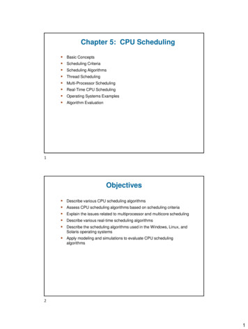
Remote PFC is an in-network flow control mechanism. Remote PFC leveragesIntel Tofino 2 Programmable Ethernet Switch ASIC’s advancedprogrammability to detect queue build and to signal congestion across the datacenter to stop the contributing sender NICs directly. PFC is used for flow controlenforcement between top-of-rack (ToR) switches and NICs for backwardscompatibility and low latency. Thereby, Remote PFC combines the strength ofedge-to-edge signaling with the strength of low-latency flow control toimplement sub-RTT remote PFC signaling.Barefoot Switch Division5
What is Remote PFC?Remote PFC does not target/does target Edge-to-Edge signaling of congestion aim 100% lossless vs min switch buffering Flow control that instantly ‘flattens the curve’ e2e congestion ctrl vs NIC flow ctrl Signaling ‘source’ flow ctrl all in sub-RTT Pause Agg/Core switches no PFC side effects Need greenfield deployment ToR-only upgrade5 ReportSender 1q13 PFCL2 framePort 12q1q2q2q3q3Src ToR Switch:Port 2Intel Tofino 2 SONiC PINSSender 2q1q23 PFCL2 frameq3Barefoot Switch Divisionq1q2q3Remote PFC signal,L3 packetAgg Coreswitches2Ingressq11 Incast trafficRemote PFC signal,L3 packetEgresscongestion Receiverto senderq1q2q2q3q3Dst ToR Switch:Intel Tofino 2 SONiC PINS4 E2E congestionsignalingforwarded afterqueuing delay6
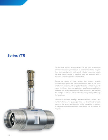
1. The programmable logic checks the congestion status of anoutgoing queue before enqueuing a packet2. If congestion is detected, a notification packet is created that skipsthe congestion and is sent directly back to the senderQueue congestion status reportIngress Pipelinedatapacket1.CongestionDetectionpkt2.Create congestionsignal packetBarefoot Switch DivisionQueueingsystemEgress PipelinedatapacketRcv hostCongestionsignalBacktosenderStd priority queuepktHigh priorityqueue7
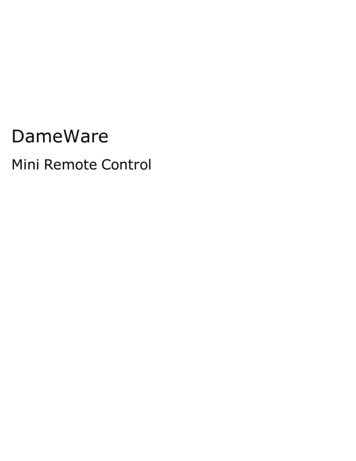
WorkloadRcv1 RoCEv2 throughput testSend1 Recv1 traffic: 4:1 incast160 flowsToR1ToR2100G Recv2 traffic: 20:1 incast160 flowsSend2100G640 flows ResultRcv2 Significantly reduce queue depthand head-of-line blocking in the networkSend3Send6Send4Port: ToR2 Recv12 MB1 MB0BRemote PFCQueue depth [bytes]Port: ToR2 Recv2PFCSend5Port: ToR1 ToR22 MB1 MBLower is better0B0s10s20s30s40s50s 0s10s20s30s40s50s 0s10s20s30s40s50sTime since first packetSee backup for workloads and configurations. Results may vary.Barefoot Switch Division8
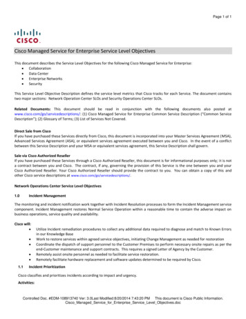
Cumulative distribution function (CDF) [P(X x)]1.00Higher is better0.900.800.707.9% P99.99reduction0.600.500.4073,3% P50reduction0.300.20Flow control mechanismPFC0.10Remote PFC0.000.05.010.015.020.025.030.0Flow completion time [s]See backup for workloads and configurations. Results may vary.Barefoot Switch Division9
Remote PFC Flattens the buffer utilization curve for incast workloads in data centers Leverages the programmability of Intel Tofino 2/Tofino 3-based ToR switchesfor sub-RTT edge-to-edge congestion signaling Compatible with standard NICs that support IEEE 802.1Qbb PFC SONiC PINS enables Remote PFC’s rapid deployment in production environments Future Upstream to SAI Ongoing efforts to standardize Remote PFC at IEEE 802.1 Generalize the Remote PFC approach to providing flow control directly in theprotocol engine in the sender as Source Flow Control (SFC)Barefoot Switch Division10
Performance varies by use, configuration and other factors. Learn moreat www.Intel.com/PerformanceIndex . Performance results are based on testing as of dates shown in configurations and may notreflect all publicly available updates. See backup for configuration details. No product orcomponent can be absolutely secure. Your costs and results may vary. Intel technologies may require enabled hardware, software or service activation. Intel Corporation. Intel, the Intel logo, and other Intel marks are trademarks of IntelCorporation or its subsidiaries. Other names and brands may be claimed as the property ofothers.Barefoot Switch Division11
12
Switch ConfigTest byTest dateSUT SetupPlatform# SwitchesHWSKUEthernet switch ASICSDE versionOSBuffer Pool allocationRemote PFC thresholdPFC thresholdBarefoot Switch DivisionSwitch Config1Switch Config2(Remote PFC “off”, PFC “on”) (Remote PFC “on”, PFC “off”)Intel04/08/2021Accton AS9516 32d-r02 (ToR1, ToR2)NewportIntel Tofino 2 Programmable Ethernet Switch 22355Ingress Lossless pool size is 7.6MB and lossy pool size is 7.6MB.Egress lossless pool size is 16.7MB, and lossy pool size is 6.4MB.N/AHeadroom size is 184KB,dynamic threshold is 4.100KBN/A13
Server ConfigTwo server models (A and B) are used at the same time in the testbedModel AModel BIntelIntel04/08/202104/08/2021Server modelTest byTest dateServer SetupPlatform# Nodes# SocketsCPUCores/socket, Threads/socketMicrocodeHTTurboPower management (disabled/enabled)# NUMA nodes per socket (1, 2, 4.)Prefetcher’e enabled (svr info)BIOS versionSystem DDR Mem Config: slots / cap / speedTotal Memory/Node (DDR, DCPMM)NICPCHOther HW (Accelerator)OSKernelWorkloadCompilerLibrariesNIC driverNIC driver versionNIC Firmware versionBarefoot Switch DivisionIntel S2600WFTSupermicro X10DRW-i3 (Send 6, Recv 1, 2)5 (Send 1, 2, 3, 4, 5)22Intel(R) Xeon(R) Gold 6240 CPU @ 2.60GHzIntel(R) Xeon(R) CPU E5-2620 v4 @ .0a6 slots / 16GB / 2934 (*)8 slots / 32 GB / 213396, 0256, 01x 2x100GbE Mellanox ConnectX-6 NIC1x 2x100GbE Mellanox ConnectX-6 NICIntel C620Intel C610/X99RoCEv2 protocol engine in Mellanox ConnectX-6 NIC RoCEv2 protocol engine in Mellanox ConnectX-6 NICUbuntu 20.04.2 LTSUbuntu 20.04.2 LTS5.4.0-66-generic5.4.0-66-genericCustom trace based on Homa (Sigcomm 2018)Custom trace based on Homa (Sigcomm 2018)“Facebook Hadoop” dataset“Facebook Hadoop” datasetgcc(Ubuntu9.3.0-17ubuntu1 20.04) 9.3.0gcc (Ubuntu 9.3.0-17ubuntu1 20.04) 9.3.0MLNX OFED LINUX-5.1-2.5.8.0 (OFED-5.1-2.5.8)MLNX OFED LINUX-5.1-2.5.8.0 (OFED-5.1-2.5.8)mlx5 coremlx5 core5.1-2.5.85.1-2.5.820.28.2006 (MT 0000000224)20.28.2006 (MT 0000000224)*The memory population is per system. For server Model A only half of the memory channels are used per socket. This is a sub-optimal memory configuration compared to the best-knownconfiguration where all memory channels are populated but is not a performance-critical issue. The performance-critical path for the workload runs in the RoCEv2 hardware engine of theRDMA NIC and accesses the memory controllers of the CPUs directly. The maximum network throughput on the NIC is limited to the port speed of 100Gbps. The maximum load on thememory controller is limited to 12.5GB/s and hence the memory controller is not a performance limiter.14
Remote PFC is an in-network flow control mechanism. Remote PFC leverages Intel Tofino 2 Programmable Ethernet Switch ASIC's advanced programmability to detect queue build and to signal congestion across the data center to stop the contributing sender NICs directly. PFC is used for flow control