Transcription
Optical Characterization of Window Materialsfor Aerospace ApplicationsKen K. Tedjojuwono*, Natalie Clark, and William M. Humphreys, Jr.NASA Langley Research Center, 18 Langley Blvd., Hampton, VA 23681-2199ABSTRACTAn optical metrology laboratory has been developed to characterize the optical properties of optical window materials tobe used for aerospace applications. Several optical measurement systems have been selected and developed to measurespectral transmittance, haze, clarity, birefringence, striae, wavefront quality, and wedge. In addition to silica basedglasses, several optical lightweight polymer materials and transparent ceramics have been investigated in the laboratory.The measurement systems and selected empirical results for non-silica materials are described. These measurements willbe used to form the basis of acceptance criteria for selection of window materials for future aerospace vehicle and habitatdesigns.Keywords: Optical windows, optical material, optical measurement, aerospace window1. INTRODUCTIONAn enduring need has been identified in the aerospace community over the past decade to develop transparent windowmaterials that meet or exceed the optical, mechanical, and structural properties of current windows in such applicationsas crewed spacecraft, crewed habitats and high performance aircraft. For many applications, windows are designated as“criticality 1”, meaning that a failure will result in a loss of life, loss of vehicle, or loss of a habitat. Traditionally, fusedsilica glass has been the material of choice for NASA space missions (e.g., Apollo, Shuttle, and ISS) but this materialentails an unacceptable weight penalty. Because it is a brittle material, glass is highly unreliable for use as a primarystructure, and therefore designs are penalized by the requirement of providing window pane redundancies. For thesereasons, the former NASA Exploration Technology Development Program (ETDP) tasked the Advanced Sensing andOptical Measurement Branch (ASOMB) at NASA Langley (as part of a wider effort involving the Johnson Space Centerand the Glenn Research Center) to commission an optical metrology laboratory capable of quantitatively measuring anumber of optical parameters for candidate lightweight or novel window materials for aerospace use, with the goal ofestablishing an open database of material properties that could be used by designers of future vehicles and habitats.Silica glass materials have high optical transmittance, melting temperatures and wide ranges of chemical inertness butare limited by their brittleness and several significant structural reliability issues. In the case of optical plastic polymers,they are relatively inexpensive, easily massed produced and are not as brittle as their silica counterparts. However,plastic polymers are limited by their low melting temperatures, easily scratched soft material, and reactivity with manychemicals and solvents. Transparent ceramic materials show excellent optical characteristics and superb structuralstrength but require special manufacturing.As part of the funded ETDP study of transparent optical materials for crewed spacecraft and habitat use, severalmaterials were evaluated in the new optical metrology lab at Langley. These included silica, polycarbonate, polymethylmethacrylate (PMMA, acrylic), polyurethane, Aluminum Oxinitride (ALON 1), and magnesium aluminate spinel(spinel). The optical parameters studied included spectral transmittance, haze, clarity, optical birefringence, striae,wavefront quality, and wedge. Experimental setup and representative measurement results are described below.*ken.k.tedjojuwono@nasa.gov; phone 1 757 864-45951The use of trade, firm, or corporation names in this work is for the information and convenience of the reader. Such use doesnot constitute an official endorsement or approval by the National Aeronautics and Space Administration of any product orservice to the exclusion of others that may be suitable
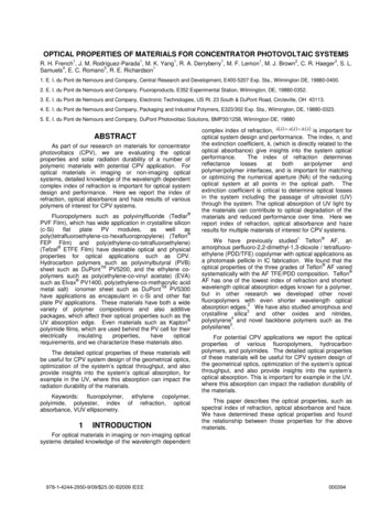
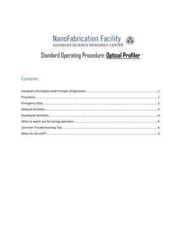
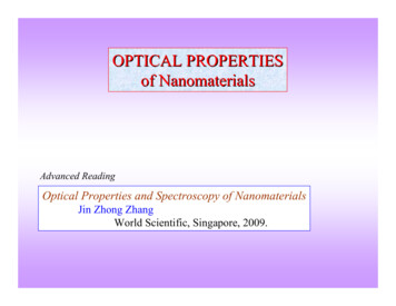
2. MEASUREMENT METHODS2.1 Optical Transmittance, Haze, and ClarityThe luminous transmittance, transmissivity, or transmittance τ of a window pane is defined as the ratio of the transmittedintensity, It, to the incident intensity I0, and can be expressed aswhere R is the reflectivity, k is the absorption coefficient, and d is the optical path length across the window.The spectral transmittance has been measured using an HP 8452A Diode-Array UV-Visible Spectrophotometer. In thediagram of Figure 1, the light source produces a plasma discharge in a low pressure deuterium gas, which allows thedeuterium lamp to emit light over the 190 nm to 820 nm wavelength range. The concave holographic grating and a slitcombination define each wavelength projected onto the appropriate photodiode of the diode array.Figure 1 – Diagram of the optical spectrophotometer.Light passing through optical polymer materials is also scattered and diffused which reduces the total direct transmittedlight. A BYK hazemeter is used to measure the haze, clarity, and luminous transmittance of optical windows. Haze isdefined as the percentage of the transmitted light intensity which deviates from the incident beam direction by angles 2.5 (ASTM D10031 [1]). Clarity is defined as the percentage of the transmitted light intensity which deviates from theincident beam by angles 2.5 .Figure 2 – Diagram of a hazemeter with a broadband illumination light source.The hazemeter utilizes a broadband illumination light source, shown in Fig. 2, that strikes the specimen and enters anintegrating sphere. The light, uniformly distributed by the matte white coating on the sphere wall, is measured by a
photodetector. Total transmittance is measured with the sphere outlet closed, and haze is measured with the outlet open.A ring sensor in the outlet opening measures the clarity. The entire measurement sequence is controlled automatically.2.2 Optical BirefringenceOptical birefringence is measured using the photoelastic modulation technique with an Exicor 150AT instrument. Themeasurement system consists of a HeNe laser light source and two photo elastic modulators operating at 50 and 60 kHzto control the modulation of the beam polarization states. A detector measures the beam polarization states and thesignals are used to determine the retardation and fast axis orientation of the optical window specimen.2.3 Striae and HomogeneityStriae observed in glasses are locally limited areas that are optically detectable as a result of a refractive index thatdiffers from that of the surrounding glass. Shadowgraphy is a viable, economic choice for measuring striae. The threemeter shadowgraph has been reported by Stroud [2] to be used by Schott Glass for routine striae inspection. Schlierenand shadowgraph systems have been used to perform qualitative evaluations, and found to complement each other, eventhough sometimes one is more sensitive than the other. For some non-silica materials, the striae can be very complexand require further considerations on how to evaluate it. For glass materials, even the three available standards areconsidered to not sufficiently address the striae quality grades [2]. Figure 3 shows the set-up of the schlieren system, aclassical off-axis system using a 75 watt Xenon arc lamp as the incoherent light source. Both concave mirrors are 16” indiameter with 96” focal lengths. The two mirrors and a pinhole arrangement create a collimated incoherent light beambetween the mirrors, with the optical window test article located in the beam path. The knife edge blocks parts of thelight which is refracted by any refractive index irregularities and will not be further collimated in the test area. A cameracaptures the image of the test area with darker spots shown where the light is refracted and blocked by the knife edge.Ideally, the knife edge should be rotated to allow for observations of every direction of the refractive effects.Figure 3 – Diagram of the off-axis schlieren system.2.4 Wavefront QualityThe wavefront quality is measured by a Fizeau interferometer as shown in Fig.4, in which a monochromatic HeNe laserpoint light source is collimated onto a reference flat mirror. The plane wavefronts double pass through the testedwindow and interfere with other wavefronts which are not passed through the window material onto the interferogramplane. The interference fringes are very similar to Newton ring fringes from an optical flat, except that in a Fizeauinterferometer, the window specimen does not have any contact with other optical components. The interferometer is a6-inch aperture zygo with an RMS repeatability of λ/20,000, a peak to valley repeatability of λ/1500, and a resolutionof better than λ/8,000 (double-pass).
Figure 4 – Diagram of a Fizeau interferometer to measure the transmitted wavefront quality.2.5 WedgeThe optical wedge is a measure of how parallel the frontal surface is in relation to the back surface of a window pane.Even when a window is considered to be a parallel plate, the angle between the two surfaces is not exactly zero and theinterferometer can measure this wedge angle with a resolution of one tenth of a second arc angle. The optical wedge isdefined by two factors, the wedge magnitude and wedge angle. The wedge magnitude is the nonparallelism measure ofa window which is the angle between its front and back planes. The wedge magnitude will be equal to zero for an idealparallel window plate. The wedge angle is the direction of a wedge, which is the angle between the wedge plane and thehorizontal direction on the window plane.2.6 Color BalanceThe optical wedge is a measure of how parallel the frontal surface is in relation to the back surface of a window pane.Even when a window is considered to be a parallel plate, the angle between the two surfaces is not exactly zero and theinterferometer can measure this wedge angle with a resolution of one tenth of a second arc angle. The optical wedge isdefined by two factors, the wedge magnitude and wedge angle. The wedge magnitude is the nonparallelism measure ofa window which is the angle between its front and back planes. The wedge magnitude will be equal to zero for an idealparallel window plate. The wedge angle is the direction of a wedge, which is the angle between the wedge plane and thehorizontal direction on the window plane.2.7 Refractive Index / Abbe NumberThe most important optical properties of transparent materials, namely the refractive index and Abbe number, arederived from data sheets supplied by manufacturers and have not been independently tested in the Langley metrology laband are beyond the scope of the present study.3. OPTICAL WINDOWS SPECIMENSCandidate materials for optical windows can be categorized into three groups: silica-based, polymer plastics, andtransparent ceramics. Among the glass materials, fused silica is considered one of the best optical materials for visiblewavelengths. Although there are hundreds of optical polymer materials, there are only a limited number of polymersavailable in large plate dimensions as required for windows applications. A lot of optical polymer materials come inpellets form to be molded into lenses or glasses and cannot be readily made into large window pane structures. Theoptical polymers tested in this study are polycarbonate, acrylic, and polyurethane. The transparent ceramics tested areALON and spinel; commercially available alumina (sapphire) is a candidate to be tested in the future.The choice of optical plastic materials is very limited, which means that there is not a lot of freedom in the optical designprocess. One very important limitation is the high thermal coefficient of expansion and relatively large change inrefractive index with temperature The refractive index of plastic materials decreases with temperature (it increases in
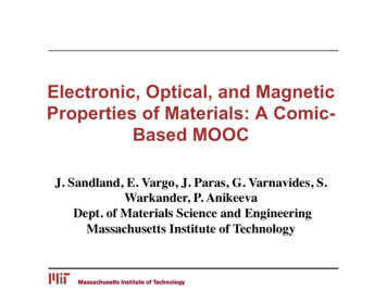
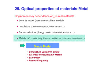
glasses), and the change is roughly 50 times greater than in glass. The thermal expansion coefficient of plastic isapproximately 10 times higher than that of glass.3.1 Polycarbonate (Cl6H14O3)nPolycarbonate (PC) is a transparent thermoplastic which is the polymer of Bisphenol A containing carbonate groups.Polycarbonate (Lexan , Makrolon ) sheets have the highest working temperature (120 C) among optical plasticmaterials and high impact-resistance, but unfortunately also low scratch-resistance. Due to the requirement of aprotecting coating, polycarbonate sheets are commonly fabricated through an extrusion process which introducesnonhomogeneity and birefringence in the material.3.2 Polycarbonate (C5H8O2)nPlexiglas, PMMA (Polymethy1 methacrylate) is a transparent thermoplastic, and synthetic polymer of methylmethacrylate. Cell-cast acrylic from Spartech called Polycast S-A-R is produced by applying a very hard, highlycrosslinked polysilicate coating to a substrate. This coating provides Spartech Polycast SAR sheets with a surface thathas 45 times the abrasion resistance of uncoated acrylic. It also has five times the impact resistance of glass and weighshalf as much.3.3 Polyurethane (C25H42O6)nCleargard , by Simula Inc., has a lower density than acrylic or polycarbonate, and reportedly a superior ballisticperformance compared to conventional transparent polymers like acrylic and polycarbonate, and superior abrasionresistance compared to acrylic and polycarbonate. Polyurethane also performs better at temperatures -25 F ascompared to PC.3.4 Aluminum Oxynitride (ALON, Al23O27N5), Al23-1/3xO27 xN5-x (0.429 x 2)The Raytheon company developed Aluminum Oxynitride, ALON, which has the physical appearance of glass but hasphenomenal ballistic properties, as an alternative material for sapphire for missile seeker window applications. ALONproducts possess excellent light transmission, impact resistance and structural stability over a wide range oftemperatures. Surmet Corp. acquired the Raytheon technology and is currently the main supplier of ALON. The phasediagram of ALON [3] is shown in Fig. 5 and is very important in its synthesis preparation. Synthesis techniques includehot pressing and pressureless sintering.Figure 5 – Phase diagram for the A12O3 – AlN pseudo-binary (McCauley, 1981)3.5 Magnesium Aluminate Spinel (MgAl2O4)Spinel Optical Ceramic is a transparent polycrystalline ceramic whose combination of high hardness, light weight andbroadband optical properties make it a leading candidate for stringent optical applications and transparent armor. Its
transmission window spans the range from 0.19 μm to 6.0 μm and exceeds that of single crystal sapphire and ALON.Additional advantages versus sapphire and ALON include optical isotropy and high temperature stability, respectively.4. EXPERIMENTAL RESULTSIn addition to the NASA space shuttle glass, over fifty specimens of various optical polymers and ceramics materialshave been tested. Most of the specimens measure 6 x 6 x 0.5 inch in size and include polycarbonate (Lexan andMakrolon), stretched and cast acrylic (Acrivue and Spartech), polyurethane (Cleargard), ALON (Surmet), and spinel(ArmorLine) windows.Note that the results shown subsequently for various materials and groups of materials are representative only, and arenot intended to form the basis of selection criteria for window designs. Such criteria can be derived only from detailedanalysis of the sum total of measurements taken on many different specimens.2.1 Transmittance, Haze and ClarityFigure 6 shows the transmittance curves of shuttle glass and high transmittance polymer panes. The values are drawn asa function of UV-VIS wavelengths. The values of total luminous transmittance from incoherent light, haze, and clarity ofdifferent materials are shown in Fig.7. Polymers which can be cast during fabrication will have a better homogeneitycompared to the polymers which are extruded (stretched) during the manufacturing process. Polymer materials withbetter homogeneity will produce less haze.Figure 6 – Transmittance curves of shuttle glass and some high transmittance polymers.Figure 7 – Total luminous transmittance, clarity, and haze of Orion candidate materials.
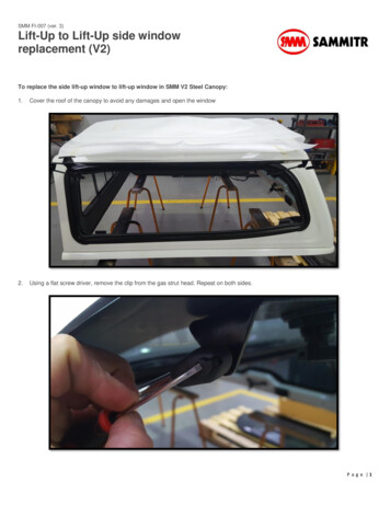
2.2 SchlierenFigure 8 shows the schlieren images of six different materials, in this series polycarbonate material shows a great degreeof inhomogeneity.Figure 8 – Schlieren Images Comparing Homogeneity of (top, l-r:) Lexan, Polycast, Acrivue, (bottom, l-r:)Cleargard, ALON, and SpinelFigure 9 shows the comparison of two sets of schlieren and shadowgraph images. For the polycarbonate case, schlierenimage will produce a more sensitive response, while for ALON material they are practically the same.(a)(b)Figure 9 – The schlieren (left) and shawdowgraph images (right) of (a) Lexan and (b) ALON, the schlieren image ismore sensitive to the inhomogeneity of Lexan than ALON.
2.3 BirefringenceThe retardance map and contours of six separate 6 x 6 inch optical specimens are shown in Fig. 10. Ideally a perfectoptical material would exhibit uniform retardance across the entire face of the specimen. However, many times thecutting or sawing process along the circumference of the sample affects the material with higher birefringence valuesappearing along the edges. For harder material like ALON and spinel, additional polishing will also produce additionalstress-induced birefringence along the perimeter. This measurement explains why the area with effective uniformbirefringence values is less than the actual area of the material.
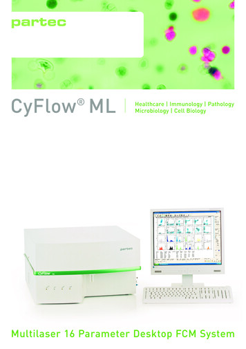
Figure 10 – Retardation maps and contour maps for 6 x 6” plates of (top to bottom) Lexan, Spartech, Acrivue,Cleargard, ALON, and spinel specimens, unit step of measurement is 5 x 5 mm2.2.4 Wavefront QualityFigure 11 depicts a pair of interferograms taken on a single piece Space Shuttle fused silica windshield pane. The topinterferogram was acquired with optical piston and tilt removed from the measurement, whereas the bottominterferogram has defocus removed as well. The interferograms are indicative of a high quality window which preservesthe salient features of the wavefront passing through the pane. Figure 12 shows a similar pair of interferograms for aspecimen of ALON. While visually the wavefront quality appears less uniform, in actuality the RMS measure ofwavefront variability indicates that ALON is very acceptable in regards to wavefront preservation.Figure 11 – Wavefront measurement for shuttle fused silica.
Figure 12 – Wavefront measurement for ALON window.It is noted that when wavefront measurements are taken for optical materials with high haze and scattering, thewavefront may have a lot of drop out signals and the wavefront calculation often cannot be completed. This can bepartially corrected by using a different reflectivity mirror which will create equal optical signals along bothinterferometer paths for optimum fringe visibility.2.5 Color Balance TestingFigure 13 depicts the results of a color balance test on a sample of Cleargard transparent polyurethane using a highquality digital camera with a 400-mm, f/2.8 attached lens. The left image is with no window specimen in front of thecamera, the right image is taken through the specimen. In this particular case, although there is some defocus present,the ability of the material to preserve fundamental colors is acceptable.Figure 13 – Color balance testing measured using digital camera and color balance target Cleargard TransparentPolyurethane, (a) No Window, f#2.8, 400-mm Lens, (b) Cleargard Sample, f#2.8, 400-mm Lens5. SUMMARYA new optical metrology laboratory has been established at the NASA Langley Research Center to allow the collectionof comprehensive measurements of optical properties for transparent specimens. The capabilities of the laboratoryinclude the measurement of wavefront quality, birefringence, haze and clarity, straiae, color balance, transmittance and
optical wedge. As part of a funded activity by the former NASA Exploration Technology Development Program,candidate specimens of silica, polymer, and optical ceramics were characterized in the laboratory. Representative resultsfrom the measurement of these materials have been shown to illustrate the range of capabilities in the new laboratory.The full ensemble of empirical measurements performed on material specimens will be used as the basis for a materialdatabase of optical properties of transparent materials for use by future designers of aerospace systems, vehicles, andhabitats, allowing specific requirements for those systems to be met [4].ACKNOWLEDGMENTSThe authors would like to thank Steve Jones in ASOMB for his support of schlieren measurements. The authors alsoacknowledge Steve Borg, Patti Davis, and Benny Lunsford of ASOMB for their data acquisition support, and BillCulliton for enhancements to the laboratory data acquisition and scanning system. Acknowledgment is also extended toMark Kulick (Analytical Mechanics Associates, Inc.) for superb fabrication support for the study.REFERENCES[1] ASTM International, ASTM D 1003 – 07, “Standard Test Method for Haze and Luminous Transmittance ofTransparent Plastics.[2] J. S. Stroud, “Striae quality grades for optical glass,” Opt. Eng., Vol. 42, No. 6, 2003, pp. 1618–1624 (June 2003)[3] J.W. McCauley, and N. D. Corbin, “High temperature reactions and microstructures in the Al203 -AlN System,” in'Progress in Nitrogen Ceramics'. Proc. NATO Adv. Study Institute on Nitrogen Ceramics, held at Univ. of Sussex(27 July-7 Aug., 1981)[4] “Orion Crew Exploration Vehicle Window Optical Properties Requirements”, NASA Constellation ProgramDocument CxP-72407, October 29, 2009Van Derlofske, J. F., "Computer modeling of LED light pipe systems foruniform display illumination," Proc. SPIE 4445, 119-129 (2001).
An optical metrology laboratory has been developed to characterize the optical properties of optical window materials to be used for aerospace applications. Several optical measurement systems have been selected and developed to measure spectral transmittance, haze, clar