Transcription
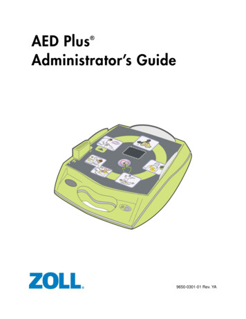
QUICK START GUIDEi.MX 8M Plus EVKi.MX 8M PLUS EVK
ABOUT THE i.MX 8M PLUS EVKThe i.MX 8M Plus applications processor is the latest member of the i.MX 8M family. Itexcels in machine learning, vision, advanced multimedia and industrial IoT applications.Elevating edge intelligence, i.MX 8M Plus processors are the solid foundation for smarthomes to smart cities, Industry 4.0 and beyond.FeaturesCompute Module: i.MX 8M Plus applications processorwith up to five cores:– 4 Arm Cortex -A53– 1 Arm Cortex-M7 LPDDR4 32-bit, 6 GB eMMC 5.1, 32 GB Two 1 Gbit/s Ethernet– Port0 supports 1 Gbit/s Ethernet– Port1 supports 1 Gbit/s Ethernetwith TSN AW-CM276MA (NXP 88W8997): Wi-Fi 5 (802.11ac) 2 x 2 dual-band (2.4/5GHz) and Bluetooth 5.1 QSPI NOR flash, 32 MB Mini-SAS MIPI-DSI connector fordisplay Power management IC (NXPPCA9450C) Two Mini-SAS LVDS connectors fordisplayBase Board: HDMI Type-A connector for display MicroSD card connector Two Mini-SAS MIPI-CSI connectors forcamera Two Type-C connectors: Port0 is the only power supply port;Port1 is a USB3.0 connector Two female DB9 connectors for CAN One USB3.0 Type-A connector 3.5 mm headset for audio2 USB-to-serial converter for debug
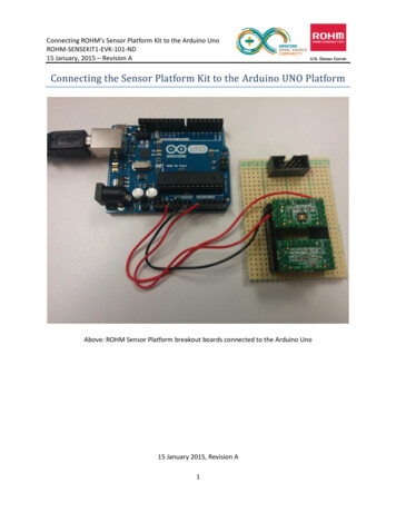
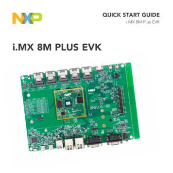
QUICK START GUIDE i.MX 8M Plus EVKGET TO KNOW THE i.MX 8M PLUS EVKDisplay CameraMIPI-DSI MIPI-CSIDisplayLVDSDisplayHDMIKeysPower SwitchBOOT SwitchesI2C ConnectorJTAGExpansionConnectorCPU BoardBase BoardPower BoardConnectorAudio HeadsetUSB MicroBDebug PortType C Port 0(Power Supply)Type C Type A EthernetPort 1Port 2 RJ45-2(USB3.0) (USB3.0Host)CAN BusDB9-2Figure 1: Top view i.MX 8M Plus EVK3
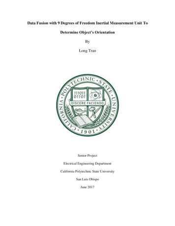
GET TO KNOW THE i.MX 8M PLUS EVKCONTINUEDMicroSD CardConnectorM.2 KEY-E SlotWi-Fi /Bluetooth ModuleWi-Fi/BluetoothAntennaFigure 2: Back view i.MX 8M Plus EVKFigure 3. i.MX 8M Plus EVK with Heatsink4
QUICK START GUIDE i.MX 8M Plus EVKGETTING STARTEDUnpack the KitPrepare AccessoriesThe i.MX 8M Plus EVK (8MPLUSLPD4EVK) is shipped with the items listed inTable 1. Ensure the items are available inthe EVK box.The following items in Table 2 arerecommended to run with the i.MX 8MPlus EVK.Table 1 Kit ContentsITEMDESCRIPTIONTable 2 Customer essory CardMIPI-DSI to HDMI adapter boardIMX-LVDS-HDMIAccessory CardLVDS to HDMI adapter boardMX8-DSIOLED1/MX8DSI-OLED1AMIPI - DSI 1080p OLED displayMini-SAS cable8” Mini-SAS cableHDMI DisplayHDMI display that supports a minimumresolution of 1080p60.Linux BSP image programmed ineMMCHDMI CableHDMI cable to connect the HDMIboard to HDMI displayQuick Start GuideMouseUSB mouseUSB Hub2 or 4 port USB hubEVK Boardi.MX 8M Plus EVKPower SupplyUSB Type C 45 W power deliverysupply, 5V/3A; 9V/3A; 15V/3A;20V/2.25A supportedUSB Type-CCableCable – Assembly, USB 3.0, Type-Cmale to micro-B maleUSB micro-BCableCable – Assembly, USB 2.0, Type-AMale to Micro-B MaleUSB Type-C to AAdapterAdapter – USB 3.0, Type-C male toType-A femaleSoftwareDocumentation5
GETTING STARTEDCONTINUEDDownload Software and ToolsInstallation software and documentation are available at www.nxp.com/imx8mplusevk.The following are available on the website:Table 3 Software and ToolsITEMDESCRIPTION Schematics, layout and Gerber files i.MX 8M Plus EVK Board Hardware User’s GuideDocumentation Quick Start Guide Hardware Design Guide Power Consumption MeasurementSoftware DevelopmentLinux BSPs, Android BSPsDemo ImagesCopy of the latest Linux and Android BSP images that are available to program on to the eMMCor SD Cardi.MX 8M Plus software can be found www.nxp.com/IMXLINUX and www.nxp.com/IMXANDROID6
QUICK START GUIDE i.MX 8M Plus EVKSETTING UP THE SYSTEMThe following will describe how to run thepre-loaded Linux image on the i.MX 8MPlus EVK.The console print will output on “EnhancedCOM port,” which can be found in “DeviceManager” of the PC.1If the serial port is not recognized,download and install updated drivers aslisted in the section “Debug Serial Console”below.Confirm BootSwitchesThe boot switches should be set to bootfrom the eMMC. SW4[1-4] are used forboot. See table.BOOT DEVICEeMMC/uSDHC3SW4 [1-4]00101 ON 0 OFF2Connect USBDebug CableConnect the micro-B end of a USB cableinto debug port J23. Connect the otherend of the cable to a PC acting as ahost terminal. Four UART connectionswill appear on the PC, the third port forthe Cortex-A53 core and the fourth forCortex-M7 core system debugging.Open the terminal window (i.e., HyperTerminal or Tera Term), choose the thirdCOM port number and apply the followingconfiguration. Baud rate: 115200 Data bits: 8 Parity: None Stop bits: 13Connect HDMIDisplayConnect an HDMI cable to the HDMIconnector Jack J17. Connect the otherend of the cable to a HDMI display panel.7
SETTING UP THE SYSTEM4CONTINUEDConnectMouseConnect the mouse to the USB hostconnector J7.5ConnectPower SupplyConnect the USB Type-C plug of thePower Supply to J5 (USB Type-C Port0),then power up the board using switchSW3.Use only J5 for power delivery to theboard.6BoardBoot UpAs the board boots up, you will see 4penguins appear in the upper left-handcorner of the monitor, and then you willsee the Linux terminal icon on the topleft and the timer on right top corner.Congratulations, you are up and running.8
QUICK START GUIDE i.MX 8M Plus EVKADDITIONAL INFORMATIONBoot SwitchesSW4[1-4] is the boot configuration switch, the default boot device is eMMC/uSDHC3,as shown in Table 4. If you want to try other boot devices, you need to change theboot switches to corresponding values as listed in Table 4.Table 4 Boot Device SettingsBOOT DEVICESW4-1SW4-2SW4-3SW4-4Boot From Fuses0000USB Serial Download Mode0001USDHC3 (eMMC boot only, SD3 8-bit) Default0010USDHC2 (SD boot only, SD2)0011NAND 8-bit single device 256 page0100NAND 8-bit single device 512 page0100QSPI 3B Read0110QSPI Hyperflash 3.3V0111ecSPI Boot1000Note: 1 ON 0 OFF X Don’t CareDebug Serial ConsoleWindows users may need to update the serial drivers on your computer. The driverscan be found at https://www.ftdichip.com/Drivers/VCP.htm9
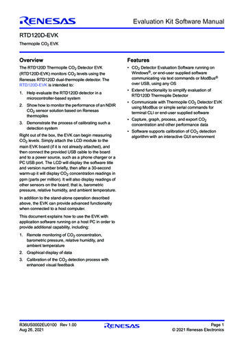
ADDITIONAL INFORMATIONCONTINUEDDo More with Accessory BoardsMX8-DSI-OLED1/MX8-DSI-OLED1A:MIPI-DSI 1080P OLED DISPLAYMINISASTOCSI:MIPI-CSI CAMERA MODULEUse this OLED display for display and touchscreensupport.Use this MIPI-CSI camera module for machine vision, videostreaming and recording.IMX-MIPI-HDMIIMX-LVDS-HDMIMIPI-DSI to HDMI adapter card (Mini SAS) to connectMIPI DSI output to HDMI (Color may vary)LVDS-to-HDMI converter adapter card (Mini SAS) to connectLVDS output to HDMI (Color may vary)10
QUICK START GUIDE i.MX 8M Plus EVKADDITIONAL INFORMATIONCONTINUEDBASLER ADD-ON CAMERA KIT: 4KP30 MIPI-CSI CAMERA MODULEUse this Basler add-on camera kit for up to 4Kp30 machine vision support on EVK. More information can be found at:www.baslerweb.com/imx8mplus. Dart camera module– designed for mass productionM12 lens– exchangeableMini-SAS adapter– for Basler dart BCON for MIPI standard connectorFlat flex cable– 200 mm lengthSUPPORTWARRANTYVisit www.nxp.com/support for a listof phone numbers within your region.Visit www.nxp.com/warranty forcomplete warranty information.11
This device complies with Part 15 of the FCC Rules. Operation is subject to the following two conditions:(1) This device may not cause harmful interference, and(2) This device must accept any interference received, including interference that may cause undesired operation.Attention that changes or modification not expressly approved by the party responsible for compliance could void the user’sauthority to operate the equipment.Note: This product has been tested and found to comply with the limits for a Class B digital device, pursuant to Part 15 of the FCCRules. These limits are designed to provide reasonable protection against harmful interference in a residential installation. Thisproduct generates, uses, and can radiate radio frequency energy and, if not installed and used in accordance with the instructions,may cause harmful interference to radio communications. However, there is no guarantee that interference will not occur in aparticular installation. If this product does cause harmful interference to radio or television reception, which can be determinedby turning the equipment off and on, the user is encouraged to try to correct the interference by one or more of the followingmeasures:—Reorient or relocate the receiving antenna.—Increase the separation between the equipment and receiver.—Connect the equipment into an outlet on a circuit different from that to which the receiver is connected.—Consult the dealer or an experienced radio/TV technician for help.This equipment should be installed and operated with a minimum distance 20cm between the radiator and your body.The following information is provided per Article 10.8 of the Radio Equipment Directive 2014/53/EU:(a) Frequency bands in which the equipment operates.(b) The maximum RF power transmitted.PN8MPLUSLPD4EVKRF TECHNOLOGY(A) FREQ RANGES (EU)(B) MAX TRANSMITTED POWERWLAN 2.4 GHz Mode 802.11b/g/n2412 MHz – 2472 MHz18.5 dBmWLAN 5 GHz Mode 802.11a/n/ac5180 MHz – 5825 MHz15 dBmBLE2402 MHz – 2480 MHz4 dBmBluetooth BR/EDR2402 MHz – 2480 MHz4 dBmEUROPEAN DECLARATION OF CONFORMITY (Simplified DoC per Article 10.9 of the Radio Equipment Directive 2014/53/EU)This apparatus, namely 8MPLUSLPD4-EVK, conforms to the Radio Equipment Directive 2014/53/EU.The full EU Declaration of Conformity for this apparatus can be found at this location: www.nxp.com/i.MX8MPLUSwww.nxp.com/iMX8MPLUSEVKNXP and the NXP logo are trademarks of NXP B.V. All other product or service names are the property of theirrespective owners. The Bluetooth word mark and logos are registered trademarks owned by Bluetooth SIG, Inc.and any use of such marks by NXP Semiconductors is under license. Windows is a registered trademark of theMicrosoft Corporation. Arm and Cortex are trademarks or registered trademarks of Arm Limited (or its subsidiaries)in the US and/or elsewhere. The related technology may be protected by any or all of patents, copyrights, designsand trade secrets. All rights reserved. 2021 NXP B.V.Document Number: 8MPLUSEVKQSG REV 1Agile Number: 926-46371 REV A
2Connect USB Debug Cable Connect the micro-B end of a USB cable into debug port J23. Connect the other end of the cable to a PC acting as a host terminal. Four UART connections will appear on the PC, the third port for the Cortex-A53 core and the fourth for Cortex-M7 core system debugging. The console print will output on "Enhanced