Transcription
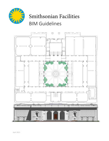
Smithsonian FacilitiesBIM GuidelinesApril 2021
Smithsonian FacilitiesBIM GuidelinesTABLE OF CONTENTSLIST OF FIGURES .IIILIST OF TABLES .IIIDOCUMENT REVISION LIST .IV1.INTRODUCTION . 12.BIM PROJECT EXECUTION PLAN (PXP) REQUIREMENTS . 22.1 BIM Execution Plan Overview. 22.2 Procurement Strategy and the PxP . 22.3 BIM Sharing . 2Design. 2Construction Documents/Bid Set. 3Construction Phase . 32.4 BIM Responsibilities . 32.5 BIM Software . 32.6 BIM Goals and BIM Uses in the PxP . 5Existing Conditions Modeling. 5Design Authoring . 6Design / Model Review. 63D Model Coordination / Clash Detection (“Interference Checking”). 7SF Asset Management . 8As-Built / Record Modeling. 82.7 BIM LOD Requirements . 103.SF REVIT TEMPLATES AND REVIT TEMPLATE USER GUIDE . 113.1 Overview of the Templates . 113.2 SI-GIS and Space Naming . 113.3 Model Ownership and After-Project Use. 124.FILE ADMINISTRATION . 124.1 Model, View and Sheet File Naming . 12SF Model File Naming . 12SF View Naming . 13SF Sheet Naming . 13Sketches and Supplemental Drawing File Names . 14SF Combined PDF Naming . 184.2 Federated Model File Coordination . 194.3 Electronic File Storage . 195.PROJECT DELIVERABLE STANDARDS . 205.1 Project Folder Structure . 205.2 Project Collaboration and Data Security . 20April 2021Page ii
Smithsonian FacilitiesBIM Guidelines5.3 BIM Deliverables . 21Design. 21Construction . 25Final Deliverables/As-Built Documentation . 265.4 Autodesk Revit BIM Deliverables Checklist. 265.5 CAD Deliverables from BIM . 27Sheet Drawing Submission Standards . 27Standard Title Block and Cover Sheet . 30SI Sheet Sizes . 31SF Project Units, Fonts and Dimensions . 32Symbols . 33SI Space Class Determination for GIS and TRIRIGA Facilities Center . 35LIST OF FIGURESFigure 4-1: File Naming Structure . 12Figure 4-2: Sheet Numbering System and Sheet File Naming System . 14Figure 5-1: Project Folder Structure. 20Figure 5-2: Custom SF annotation symbols . 33Figure 5-3: Custom SF view title symbols . 33Figure 5-4: SF CAD symbols available from the Smithsonian Facilities A/E Center website . 34LIST OF TABLESTable 2-1: BIM Software by Discipline/Use for Project Development . 4Table 2-2: BIM Uses . 9Table 2-3: Summary of the BIM Forum Level of Development (LOD) Definitions. 10Table 4-1: Components of the BIM file name(s) . 12Table 4-2: Discipline Codes . 15Table 4-3: Drawing Type Codes . 17Table 4-4: Sheet Sequence Numbers . 18Table 4-5: Components of the Combined PDF file name. 18Table 5-1: Design Deliverables . 24Table 5-2: BIM Deliverable Checklist. 26Table 5-3: Layer Standards for Standard Base Plans – Site Plan. 28Table 5-4: Layer Standards for Standard Base Plans – Floor Plan . 29Table 5-5: SI Sheet Sizes. 31April 2021Page iii
BIM GuidelinesSmithsonian FacilitiesDocument Revision ListTaskDetailsDocument organizationRearranged some sections for better flow in thedocumentChanges as per SF naming convention in SF CADStandardsChanges as per NCS 5.0 and SF CAD StandardsNaming conventionDiscipline code changesTitle block changesWall section and detail sectionannotation changesRevision DateAutomation of some fields led to rearrangementof them on title blockWall section and detail section annotationchangesChanged from SF BIM Standards to SF BIMGuidelinesChange of OFEO to Smithsonian FacilitiesOct. 2016Adding details about the federated model filetypes and 3D PDF deliverablesRearranged some sections for better flow in thedocumentHighlighted project folder structure imageOct. 2016Added option for submission type in lieu ofsubmission dateAdded combined PDF namingMarch 2017Clarification and instructions when deviationsoccur in a projectEliminate 3D PDF RequirementsMarch 2017October 2017Clash DetectionAdded additional notes for Laser ScanningRequirementsRevised Clash Detection SectionBIM DeliverablesUpdated Deliverable RequirementsOctober 2017Text SizeText height Requirement has been changed to3mm (1/8”)Revised Layering StandardsOctober 2017September 2018SI Space Naming GuidelinesRevised Asset Management to align with newrequirementsAdded Space Naming GuidelinesLOA RequirementsAdded LOA Requirements for ModelingSeptember 2018Construction / Bid SetAdded documents that may be availableApril 2021Electronic File StorageAdded OneDriveApril 2021Document titleFile naming conventionBIM deliverable changesDocument organizationProject Folder StructureModel File Naming EditsSF Combined PDF NamingModel Review Report3D PDFLaser ScanningLayering StandardsAsset ManagementApril 2021Oct. 2016Nov 2016March 2017March 2017October 2017October 2017September 2018September 2018Page iv
Smithsonian Facilities1.BIM GuidelinesINTRODUCTIONBuilding Information Modeling, or BIM, is utilized throughout the building industry for developing anddocumenting building projects, from early in the conceptual design phase through to project delivery.“Building Information Modeling (BIM) is a digital representation of physical and functionalcharacteristics of a facility. A BIM is a shared knowledge resource for information about afacility forming a reliable basis for decisions during its life-cycle; defined as existing fromearliest conception to demolition. BIM is used for the purpose of visualization, engineeringanalysis, conflict, analysis, code criteria checking, cost engineering, as-built product,budgeting and many other purposes ” -- National BIM Standard - United States (NBIMS)The Smithsonian Institution (SI) encompasses over 12 million square feet of space in over 640 buildings inthe US, Panama, and other international locations. Management of Building Information Models (BIM) atthe SI is the responsibility of the Smithsonian Facilities office, the organization that is responsible for bothin-house design efforts and administration of repair, renovation and new construction projects for themuseums and other facilities.The purpose of this manual is to convey the key processes, responsibilities and details for BIMdevelopment for SF projects by architecture, engineering and construction (AEC) consultants. The goal ofthe standards documents is to assure accurate and consistent project deliverables.This document includes guidance for drawing appearance, BIM element standards and symbols, anddeliverable requirements. The SF BIM Standards is one of several interrelated documents that assistproject teams to fulfill the SI’s project requirements. Additional SF BIM-related guidance includes: SF BIM Integration Flowchart SF CAD Guidelines SF Revit Model Review Instructions SF BIM Execution Plan Framework Document SF BIM Content LOD Matrix SF Revit Template User’s Guide SF Revit Templates (Architectural, Mechanical/Plumbing, Electrical, Structural, & Fire Alarm /Security BIM files) Revit Model Review Checker Specification Section – 01 3250 BIM Requirements Specification Section – 01 7823 O&M Data Requirements SF Facility Asset Data Spreadsheet SI Space Naming GuidelinesApril 2021Page 1 of 38
Smithsonian Facilities2.BIM GuidelinesBIM PROJECT EXECUTION PLAN (PXP) REQUIREMENTSSmithsonian Facilities requires that a BIM Project Execution Plan (PxP) be developed for projectemploying BIM. The “SF BIM Execution Plan - Framework Document” has been developed as a templateby Smithsonian Facilities to assist project teams developing BIM execution plans, consistently across all SFBIM projects.2.1BIM Execution Plan OverviewBIM Project Execution Plans will be living documents, updated by the consultant team throughout projectdevelopment and delivery then transferred to the Contractor for updating throughout the construction.The BIM PxP works in concert with the other SF BIM guidance documents noted in Section One.Any changes made to the BIM PxP during the course of a project must be approved by the authoringparty, and reviewed and approved by the SI’s COTR (Contracting Officer's Technical Representative) forthe project.2.2Procurement Strategy and the PxPThe BIM Execution Plan (PxP) will be tailored to align with the project’s procurement method (such asDesign-Bid-Build (DBB), CM at Risk, Design-Build (DB), etc.Procurement strategies will influence whether there are separate design and construction BIMs and whowill be the responsible party for the final project BIM deliverable. Separate contracts will require aseparate BIM PxP, but should align with each other to ensure a collaborative process.When a project BIM is to be developed collaboratively for both design/documentation and construction,the BIM Execution Plan (PxP) should address how the model(s) can be handed-off between stageseffectively.2.3BIM SharingProject development is an intrinsically collaborative process. The PxP will detail BIM authoring tools, dataintegration, and collaborative team workflow environments that will be employed throughout the projectBIM development process.Listed below are the possible BIM information products that will be delivered during different stages ofthe project lifecycle.DesignThe A/E design consultants for a project shall be responsible for providing Design Intent Model(s) as partof project deliverables, as described in the project scope of work. The design phase PxP will describe thedetails of the project model, including file formats, coordination/federation of the model(s), and formatfor deliverables.April 2021Page 2 of 38
Smithsonian FacilitiesBIM GuidelinesConstruction Documents/Bid SetFor projects having a bid phase, BIM requirements will be defined and reviewed with potential bidders.The design phase PxP will be provided as part of the overall SF BIM guidance for the project.Prior to the start of construction, the following building information, obtained and developed by theArchitect and/or Engineer during the design phase, may be available to the Contractor for thedevelopment and use by the contractor during the construction process:1.Design Intent Model(s) (.rvt, .ifc, .nwc, .nwd, .dwg)2.3.Contract Documents (.pdf, .dwg)Point Clouds (.rcs)4.5.Scans of the original building design drawings (.pdf)BIM PxP (.docx, .pdf)6.7.LOD Matrix (.xlsx, .pdf)SF Facility Asset Data Spreadsheet (.xlsx)The Contract Documents are the binding document(s), the Design Intent Model(s) are provided forreference only.Construction Phase 2.4It is the contractor’s responsibility to assure that all major trades are modeled as per the contractand used for clash detection, construction phasing, and installation coordination and noted in thePxP.Subcontractor’s fabrication model(s) shall be coordinated within the Coordination model(s)andnoted in the PxP.Clash analyses and reports for the project will be detailed in the project PxP.BIM ResponsibilitiesThe PxP will detail all parties’ responsibilities in the project BIM development process.2.5BIM SoftwareThe Smithsonian BIM practice employs Autodesk Revit as their primary BIM authoring application. Thesoftware version that is used for project BIM development will be noted in the BIM PxP.Smithsonian Facilities will advise project consultants on the preferred version of any software to be usedbefore project execution. Any deviation from that version must be approved by the SI project COTR priorto commencement of work. The SF will approve version updates, if necessary, for multi-year projectsduring the course of project development.The following table shows a list of current acceptable BIM and CAD applications for SF projects. This listdoes not preclude the utilization of other software for the prescribed uses. Software other than listedbelow may be used but are subject to SI project COTR’s approval due to interoperability requirements.April 2021Page 3 of 38
BIM GuidelinesSmithsonian FacilitiesTable 2-1: BIM Software by Discipline/Use for Project DevelopmentBIM itectureAutoCAD and RevitStructureDesignStructureAutoCAD (Add-on) and RevitAs agreed by SF and projectconsultant at projectinitiationHVAC DesignHVACRevit / AutoCAD (Add-on) CADductand CADmechPlumbingDesignPlumbingRevit / AutoCAD (Add-on) CADductand CADmechElectricalDesignElectricalRevit / AutoCAD (Add-on) CADelecCivil DesignCivilAutoCAD Civil 3DFire ElectricalFabricationFire nFire ProtectionMEP CAD AutoSprinkHVACElectricalRevit / AutoCAD (Add-on) CADductand CADmechRevit / AutoCAD (Add-on) CADductand CADmechRevit / AutoCAD (Add-on) CADelecFire ProtectionMEP CAD AutoSprinkStructureRevit / AutoCAD (Add-on)CMCoordinationAll disciplines(as detailed inthe projectscope of work)All disciplinesNavisworks Manage, ReviztoModel CheckDesign ReviewApril 2021PlumbingRevit Model Review report, output toa PDF format (converted from *.htmlformat)Bluebeam, Revizto, I-ManagePage 4 of 38
Smithsonian Facilities2.6BIM GuidelinesBIM Goals and BIM Uses in the PxPBIM goals are included within the Project Execution Plan to summarize the scope of the project BIMdevelopment effort. BIM utilization for AEC project development may include existing conditionsmodeling; design visualization; design reviews; clash detection and constructability exercises; asset andspace data development; and as-built documentation.Existing Conditions ModelingDescription: A process in which a project team develops a 3D model of the existing conditions for a site,facilities on a site, or a specific area within a facility. This model can be developed in multiple ways,including laser scanning and conventional surveying techniques.An existing condition model may be used as a basis for design studies, sight line studies, movemanagement and logistics, day lighting, area calculations, space allocation studies, volume calculationsfor HVAC, planning standards, phasing studies, testing locations, and other studies relevant to the projectScope of Work (SOW). The project SOW will define the approximate area, relevant building systems, andassociated equipment to be modeled. The BIM PxP will define the agreed upon modeling effort.The SI COTR will provide access to master drawings, any partial models for preliminary modeling andcurrent exports from SI’s Facility Center (Tririga) of space and asset data. Field verification is part of thisprocess unless otherwise specified by SI. All applicable SF BIM and CAD standards and requirementsapply.At a minimum, an existing conditions model will contain: The visible architecture elements walls, floors, ceilings, columns, and roof. These elements are tobe modeled to LOD 300 with an LOA of 12mm (½”) unless noted otherwise in SOW.Assembly and product information must be added to the model as required by the SOW.Space volumes and data (numbers, functional use, space ownership)Date attribute field noting as to when the existing conditions were verified, indicating thecurrency of the model and its associated data.Optional: Element(s) may be modeled to a greater LOD and/or LOA in accordance with the SOW.MEP equipment and routing may be modeled in accordance with the SOW. Assets, furniture and fixtures may be modeled in accordance with the SOW.Extend the modeling beyond the immediate SOW areas to show context and additionalinformation based on project needs.Laser Scanning for Existing ConditionsLaser scanning is a technology-based process for capturing 3D environments, including distances, in a 3Ddigital model called a point cloud, which is comprised of millions of measured points.April 2021Page 5 of 38
Smithsonian FacilitiesBIM GuidelinesThe SI COTR will evaluate the cost and efficiency benefits of laser scanning to capture existing conditions,as well as the optional conversion of the point cloud data to BIM, based upon the size and complexity ofthe project. The scope and procedure for the laser scanning, and conversion to BIM, if specified, will beclearly stated in the project BIM PxP.The required object surface density shall be a minimum of 6mm (¼”). RGB color shall be mapped to boththe exterior and interior scans. Selected areas or objects may require a greater object surface density asdirected by COTR and/or SOW.Design AuthoringDescription: A key process in which 3D software applications are used to develop a Building InformationModel (BIM) that illustrates the design intent.The first step in design authoring for an SF project is to incorporate SF Revit template(s) as a part of theproject BIM. A project BIM may include multiple component models including the architectural, HVAC,electrical, plumbing, structural, fire protection, life safety and security disciplines. Typically, multipleengineering models may be linked to or federated with, the architectural model, as required by theproject scope.BIM authoring software shall be used to model parametric components and objects. Modeled objectsshall contain parameters and associated data applicable to the building system. The level of developmentin a project model will accumulate as the project matures. This is noted within the SF BIM Content LODMatrix. At minimum, project LOD must include all features that will accurately describe the designsolution.1. At a minimum, all required models shall be detailed to the Level of Detail required by each designphase and/or sub-phase.2. BIMs should include all geometry, physical characteristics, information and data necessary so todescribe and facilitate the design, intended construction, and cost estimating of a project,meeting the requirements noted in project’s BIM Content LOD Matrix, for each design phaseand/or sub-phase of a project.3. All drawings, simulations, and services required for analysis and review shall be extractions fromthe project BIM(s).4. Modeled elements in the project BIM need not illustrate the individual parts required for theassembly and/or the manufacture of the component. The intent of the project model is toprovide a level of detail to describe the overall size, shape, clearances, information, data forbuilding components and coordination with other components and work.Design / Model ReviewDescription: A process in which the project BIM is evaluated against a set of established criteria/rules. Thecriteria can cover compliance with spatial requirements, data or parameter completion, and establisheddrawing standards.April 2021Page 6 of 38
Smithsonian FacilitiesBIM GuidelinesModel CheckingThe SF has developed a customized rule set for use with Revit Model Review add-in application to verifythe completion of project models. The add-in application can be downloaded from the Autodesksubscription website, for installation into Revit. The SF configuration file is available for download fromthe Smithsonian Facilities A/E Center website.As part of the model development process, the project A/E team should periodically perform automatedchecks of the Revit model. Model review check reports are required to be run by the project BIM teamand delivered for every SF project milestone BIM deliverable. Additional rules can be added to theconfiguration as needed.Note that some of the checks may not pass the Revit model review as per the SF rule set provided. In thatcase, a clear explanation of the failure for each failed check in the report will be required. The explanationshould comply with the specific project exceptions that are outlined in the project execution plan (BIMPxP). All exceptions or deviations from the SF BIM guidelines should be approved by the SI Project COTRand stated in the project BIM PxP.Clash detection or collision reports allow for the identification, inspection and reporting of interferencesin a 3D project model(s). These can be generated by the project team, using either Revit or AutodeskNavisworks, and reviewed by the SF in consultation with the project team.Informal or ‘over the shoulder’ reviews can lend insight to the design development process on an ad hocbasis.3D Model Coordination / Clash Detection (“Interference Checking”)Description: A process during the coordination process that employs clash detection software to identifyconflicts between building systems by analyzing a combined or federated model. The goal of the clashdetection is to reduce the number of changes during construction due to major building interferences tozero.Clash Detection - Design:SF requires Clash Detection Reports (CDRs) from the design team at each design milestone starting at the35% design deliverable. CDRs must include the results from an automated model checking software toindicate level of model coordination and other applicable codes. Both hard and soft clashes should beincluded in the model checking process.SF classifies clashes in two categories described below:Category 1 - Clashes that can be internally resolved by a single entity (consultant or subcontractor). Thegoal is to reduce error propagation in the design and to ensure compliance with good design practicesand applicable codes and regulations.These clashes should be resolved prior to submission of a design deliverable.Category 2 – Clashes that require coordination between multiple entities. For example, this could be aclash between the structural and mechanical designs. The goal is to reduce the number and impact ofApril 2021Page 7 of 38
Smithsonian FacilitiesBIM Guidelinesfield changes during the construction phase of the project. As a best practice, clashes should be resolvedprior to submission of a design deliverable.These clashes should be resolved prior to submission of a design deliverable.At final submission models shall be free of conflicts among major systems, their subsystems and elementsthat would cause coordination issues during construction.For any unresolved clashes indicated in the final CDR at Final Submission, the design team must provide aseparate narrative explaining why the clash could not or need not be resolved.Clash Detection - Construction:Clash detection during construction is primarily a coordination tool. As in design, both hard and softclashes should be considered during the coordination process. During the construction phase, theaccuracy of fabrication models shall be verified. Prior to each fabrication or shop drawing submittal forapproval, fabrication contractors shall submit their models to the Contractor's BIM Manager forintegration into the federated model for clash detection / coordination and resolution.CDRs shall be provided with fabrication or shop drawing submittals.SF Asset ManagementDescription: SF has created the SF Facility Asset Data Spreadsheet, it is way to capture informationregarding assets outside of the BIM for use by SF to import into the
2. Contract Documents (.pdf , .dwg) 3. Point Clouds (.rcs) 4. Scans of the original building design drawings (.pdf) 5. BIM PxP (.docx, .pdf) 6. LOD Matrix (.xlsx, .pdf) 7. SF Facility Asset Data Spreadsheet (.xlsx) The Contract Documents are the binding document(s), the Design Intent Model(s) are provided for reference only. Construction Phase
