Transcription
High-Speed Networks1High Speed NetworksStudy GuideDr. Wanlei ZhouandDr. Weijia Jia
High-Speed Networks2Contents0. UNIT OUTLINE .90.1. Objective90.2. Text Books0.2.1. Main Text Book0.2.2. Reference Books9990.3. Assessment91. INTRODUCTION: THE NEED FOR SPEED AND QUALITY OF SERVICE.101.1. Study Points101.2. A Brief Networking History101.3. Milestones111.4. The Need for High Speed and Quality of Service (QoS)121.5. Advanced TCP/IP and ATM Networks1.5.1. IP-based Internet1.5.2. ATM Networks1213131.6. Review Questions132. DATA NETWORKS AND COMMUNICATION PROTOCOLS.152.1. Study Points152.2. Packet-Switch Networks2.2.1. Basic Concepts2.2.2. Switching and Routing Techniques2.2.3. X.25151516162.3. Frame Relay Networks2.3.1. Why Frame Relay?2.3.2. Frame Relay Architecture1717182.4. Congestion in Data Network and Internets2.4.1. Effect of Congestion2.4.2. Congestion Control2.4.3. Traffic Management18191920
High-Speed Networks32.5. Communication Protocol Architectures2.5.1. The OSI Protocol Architecture2.5.2. Internet Architecture2.5.3. Bridges and Routers202021222.6. Review Questions233. FAST ETHERNET: IEEE 802.3 100BASE-T .243.1. Study Points243.2. Classical Ethernet3.2.1. CSMA/CD3.2.2. Logical Link Control (LLC)2424253.3. Fast Ethernet3.3.1. Fast Ethernet Standards3.3.2. Cable Standard3.3.3. Signaling Techniques252527273.4. Configuration3.4.1. Repeaters and Switches3.4.2. Mixed 10/100 Mbps Networks3.4.3. Pure 100 Mbps Networks282828303.5. Gigabit Ethernet313.6. Analysis3.6.1. Strong Points3.6.2. Weak Points3232323.7. Review Questions324. IEEE 802.8 FDDI AND IEEE 802.12 VG-ANYLAN.334.1. Study Points334.2. FDDI Concepts4.2.1. What is FDDI4.2.2. FDDI Nodes and Networking Topology3333334.3. FDDI Medium Access Control4.3.1. Station Types4.3.2. FDDI Station Management (SMT)4.3.3. FDDI MAC Functions4.3.4. FDDI Traffic and Capacity Allocation Scheme4.3.5. Ring Monitoring343435363739
High-Speed Networks44.4. Analysis of FDDI4.4.1. Strong Points4.4.2. Weak Points4040404.5. VG-AnyLAN Architecture404.6. Hub Operation414.7. Network Layers4.7.1. DTE Reference Model4.7.2. PMI Sublayer functions4242434.8. Analysis of 100AnyLAN4.8.1. Comparison of 100VG-AnyLAN and 100BASE-T4.8.2. Strong and Weak Points of 100VG-AnyLAN4343444.9. Review Questions455. ASYNCHRONOUS TRANSFER MODE .465.1. Study Points465.2. The Architecture465.3. ATM Logical Connection5.3.1. Virtual Channel Connection5.3.2. VCC Use5.3.3. VP/VCC Characteristics:474747485.4. ATM Cells5.4.1. Header Format:5.4.2. Header Error Control4848505.5. ATM Service Categories5.5.1. Real-Time Service5.5.2. Non Real-Time Service5051515.6. ATM Adaptation Layer5.6.1. AAL Services5.6.2. Service Classification for AAL5.6.3. AAL Protocols515152525.7. ATM LANs5.7.1. Development of LANs5.7.2. ATM LAN Configurations5.7.3. Analysis of ATM LANs525253545.8. Review Questions54
High-Speed Networks56. HIGH SPEED TRANSPORT-LEVEL TRAFFIC CONTROL .566.1. Study Points566.2. Transmission Control Protocol6.2.1. TCP Header Format6.2.2. TCP Flow Control6.2.3. Effect of Window Size on Performance6.2.4. Adaptive Retransmission Timer6.2.5. TCP Implementation Policy Options5656575757586.3. TCP Congestion Control6.3.1. Congestion Control in TCP-Based Internet6.3.2. Retransmission Time Management6.3.3. Window Management585859596.4. Performance of TCP over ATM6.4.1. Protocol Architecture6.4.2. TCP over UBR6.4.3. TCP Over ABR606060626.5. Real-time Transport Protocol (RTP)6.5.1. Limitations of TCP in RT Applications6.5.2. The Transport of Real-time Traffic6.5.3. Requirement for RT Communication6.5.4. RTP Protocol Architecture6.5.5. RTP Data Transfer Protocol6262626363636.6. Review Questions647. IPV6: THE NEXT GENERATION OF INTERNET .657.1. Study Points657.2. The current Internet Protocol7.2.1. IPv47.2.2. Type of Service (TOS)7.2.3. IPv4 Options656566687.3. IPv6 Introduction7.3.1. Why IPv6?7.3.2. IPv6 Features7.3.3. IPv6 Formats7.3.4. IPv6 Header7.3.5. Flow Label7.3.6. IPv6 Addresses7.3.7. Hop-by-Hop Options Header6868697070717272
High-Speed Networks7.3.8. Other Headers7.3.9. Discussion on IPv6673737.4. IPv6 Projects7.4.1. Existing Industry Implementations7.4.2. Experiments7.4.3. Depoloyment of IPv6757575757.5. Other Projects and References777.6. Review Questions788. ROUTING FOR HIGH SPEED AND MULTIMEDIA TRAFFIC:MULTICASTING AND RSVP.798.1. Study Points798.2. Internet Routing Principles8.2.1. The Routing Function8.2.2. Autonomous Systems7979808.3. Interior Routing Protocols8.3.1. Distance-Vector Protocol: RIP8.3.2. Link-State Protocol: OSPF8080818.4. Exterior Routing Protocols8.4.1. Path-Vector Routing8.4.2. Border Gateway Protocol8.4.3. Inter-Domain Routing Protocol818282828.5. Multicasting8.5.1. Multicasting strategies:8.5.2. Requirements for Multicasting8.5.3. Internet Group Management Protocol (IGMP)8.5.4. Multicast Extensions to Open Shortest Path First (MOSPF)8.5.5. Protocol Independent Multicast (PIM)8383838484858.6. Resource Reservation: RSVP8.6.1. RSVP Goals and Characteristics8.6.2. RSVP Operations8.6.3. RSVP Protocol Mechanisms858586868.7. Review Questions879. CLIENT-SERVER COMMUNICATION USING IP SOCKETS .889.1. Study Points88
High-Speed Networks79.2. The Client-Server Model9.2.1. The Basic Client-Server Model9.2.2. Communication Services8888909.3. Distributed Application Model919.4. BSD Internet Domain Sockets9.4.1. Overview9.4.2. Network Layer: IP9.4.3. Transport Layer: TCP and UDP949495979.5. IP Socket: Basic Concepts9.5.1. Socket Model9.5.2. Internet Domain Socket Naming9.5.3. Socket Types99991001019.6. Basic Internet Domain Socket System Calls9.6.1. Some Special Functions9.6.2. Socket Creation9.6.3. Name Binding9.6.4. Connection Establishment9.6.5. Transfer Data and Discard Sockets1021021061061071079.7. Examples9.7.1. Using Stream Sockets: A Simple Example9.7.2. Using Datagram Sockets: A Simple Example10910911410. AN APPLICATION EXAMPLE: ELECTRONIC MAILS .12010.1. Study Points12010.2. Mailboxes and Addresses12010.3. Message Format12010.4. Architecture of an Email System12110.5. Mailbox Access12311. NETWORK SECURITY.12511.1. Study Points12511.2. Secure Networks11.2.1. What is a Secure Network?11.2.2. Integrity Mechanisms and Access Control12512512511.3. Data Encryption126
High-Speed Networks11.3.1. Encryption Principles11.3.2. Decryption812612711.4. Security Mechanisms on the Internet11.4.1. Digital Signatures11.4.2. Packet Filtering11.4.3. Internet Firewall12812812912911.5. Review Questions130
High-Speed Networks90. Unit Outline0.1. ObjectiveThe objective of this unit is to provide an up-to-date knowledge of high-speed networksto students. At the end of this unit, students should be familiar with the basic concepts,the architectures, the protocols, the advantages and limitations, and the recentdevelopment of various high-speed networking technologies. The knowledge gained fromthe study of this unit will enable students to make decisions in selecting suitable highspeed networking technology for their own environment and applications. Students willalso have adequate knowledge in tracking the current and future development in highspeed networks.The Study Guide is divided into four parts. The first part (Sessions 1 and 2) surveys thedevelopment in high-speed networks. The second part (Sessions 3 and 4) deals with highspeed local networks. The third part (Sessions 5, 6, 7, 8, and 9) introduces high-speedinternetworking techniques and QoS related issues. The fourth part (Sessions 10, and 11)addresses the issues of applications and network security. The Study Guide willconcentrate on the following central problems that confront the designers and applicationdevelopers of high-speed networks: the need to support multimedia and real-time trafficand applications, the need to control congestion, and the need to provide different levelsof Quality of Services (QoS) to different applications.0.2. Text Books0.2.1. Main Text Book“High-Speed Networks: TCP/IP and ATM Design Principles,” By W. Stallings, PrenticeHall, NJ, 1998. ISBN: 0-13-525965-7 ([STA98]).0.2.2. Reference Books “FDDI – A High Speed Network” A. Shah and G. Ramakrishnan, Prentice-Hall, NJ,1994. ISBN: 0-13-308388-8. “High-Speed Networking for Multimedia Applications,” By W. Effelsberg, et al.Kluwer Academic Pub. 1996, ISBN: 0-7923-9681-2. “Handbook of Data Communications and Networks,” By W. Buchanan, KluwerAcademic Pub. 1999.0.3. Assessment Progressive assessment 40% Examination 60%
High-Speed Networks101. Introduction: The Need for Speed and Qualityof Service1.1. Study Points Major historical events of computer networks. Features of different high-speed networks. Requirement for high-speed networks. ATM Architecture and Protocols.Reference: [STA98] Chapter 1.1.2. A Brief Networking HistoryHigh-Speed Networks now dominate both wide-area network (WAN) and local-areanetwork (LAN) markets. Public and private data networks have evolved from packetswitching network in 10s and 100s of kilo-bits per second (kbps), to frame relay networkoperating at up to 2 mega-bits per second (Mbps), and now Asynchronous Transfer Mode(ATM) operating at 155 Mbps or more. Fast Ethernet has evolved from 10-Mbps to 100Mbps and now Gigabit Ethernet.The following table ([STA98] p.3) shows a brief networking history.1966ARPA packet-switching experimentation1969First Arpanet nodes operational1972Distributed e-mail invented1973For non-U.S. computer linked to Arpanet1975Arpanet transitioned to Defense Communications Agency1980TCP/IP experimentation began1981New host added every 20 days1983TCP/IP switchover completed1986NSFnet backbone created1990Arpanet retired1991Gopher introduced1991WWW invented1992Mosaic introduced1995Internet backbone privatized1996OC-3 (155 Mbps) backbone built
High-Speed Networks111.3. Milestones The World Wide Web (WWW): In spring 1989, CERN (the European Lab. ForParticle Physics), Tim B. Lee proposed the idea of a distributed hypermediatechnology to facilitate international exchange of researches findings using Internet.In 1991, a prototype WWW called line-oriented browser was developed at CERN andreleased to limited population. Later, the graphically oriented browser, Mosaic,developed at the NCSA at University of Illinois by Mark Andresson and others in1992. 2 million copies of Mosaic have been delivered in a short period. Email triggered rapid growth of ARPAnet so the Web triggered explosive growth inInternet. ISDN and Frame Relay: ISDN includes the integrated services and digitalnetworking. The most noteworthy technical achievement of the ISDN effort was thedevelopment of specifications for Frame Relay. Frame Relay is now considered amatured technology. It has a proven track record and is used in many Fortune 500companies. Banks are big users of Frame Relay services, especially their automatedteller machine networks. B-ISDN: ISDN was designed to provide data rates in the range of Kbps to Mbps. Toprovide higher data rate—Mbps to Gbps—the original ISDN (also called NarrowbandISDN, or N-ISDN) was extended to Broadband ISDN (B-ISDN). ATM: Just as frame relay is a technology developed as part of the ISDN effort andnow widely used in non-ISDN applications, so ATM is a technology developed aspart of the B-ISDN effort and now widely used in non-B-ISDN applications. ATM isbecoming popular because it supports transport of data, video and voicecommunications over a single infrastructure. While data is somewhat resilient, videoand voice applications demand timely and sometimes high bandwidth. ATM bringstogether these features and offers high-speed communication. Most of today’s LANoperate at 4Mbps or 10Mbps. High speed LANs can operate at 100Mbps. ATMprovides LAN and WAN connectivity at 155Mbps. ATM standards are beingdeveloped in the marketplace. The cost of ATM has also started to decrease. Withstandardization and a better cost/benefit model, ATM should be one of thetechnologies of the future. Marketplace Examples: T-1 networking will continue to be a viable option for manyyears. While T-1’s is not new technology, it is a proven high bandwidth solution formany applications, including imaging, data communication and video conferencing.Many government agencies and commercial companies have become big users of T1’s. It is safe to say that most states have successfully deployed T-1’s as part of theircommunications infrastructure. ATM utilization is not as widely deployed as T-1 and Frame Relay communications.The military has begun implementation of ATM based projects. The US Army isdeploying this technology at Fort Bragg, North Carolina, Fort Hood, Texas and FortStewart, Georgia. Three defense agencies at Fort Belvoir, Virginia are also usingATM as their backbone. Case Western Reserve University in Cleveland, Ohio isusing ATM technology all the way to the desktop so students can work on
High-Speed Networks12assignments and even take classes via video over the network. North Carolina hasimplemented an ATM backbone for education and government use across the state. Leading Vendors & Users: The regional telephone companies like Ameritech,BellSouth, Pacific Bell, etc., along with national communications providers likeAT&T, MCI and US West are the major providers of both T-1 and Frame Relaynetworking services. ATM is still fairly new territory for vendors. There are a largenumber of hardware and software vendors providing ATM products today. Sincethere is not a clear standard for ATM, the major internetworking vendors seem to bethe biggest players in this technology. Companies like Bay Networks, Cascade, Cisco,Digital Equipment Corporation, FORE Systems, General DataComm, HewlettPackard and IBM are just a few of the companies offering ATM products. Severaltelephone companies like MCI and US West are offering ATM solutions as well.Local and regional cable television providers have moved into this service area Public network infrastructure corresponds to B-ISDN and consists of publictelecommunications networks that support public telephony, cable TV (CATV), andWAN services. ATM LAN: ATM switches can serve as a backbone network in a local setting tointerconnect a variety of traditional LANs (e.g. Ethernet). ATM WAN includes enterprise networks operating over leased lines such as opticalfiber and wireless links.1.4. The Need for High Speed and Quality of Service (QoS)Emergence of High-speed LANs: In the 1990s, 2 significant trends have altered the roleof the PC and LAN: (1) The speed and computing power improvement of PCs, and (2)MIS (management information systems). Organisations have recognised the LAN as aviable and essential computing platform.The following are examples of requirements that call for high-speed LANs: Centralized server farms: There is need for users, client systems to be able to accesshuge amounts of data from multiple centralized servers. Power work groups: These groups typically consist of a small number of cooperatingusers who need to draw massive data files across the network. High-speed local backbone.Users of high-speed networks require different quality presentations at different times.These different quality presentations can be mapped into different parameter values.Quality of Service (QoS) specifies a set of parameters that can be assigned numericalvalues. However, quality of the presentation is a matter of user’s perception. Thisperceptual nature of QoS makes it subjective and difficult to quantify.1.5. Advanced TCP/IP and ATM Networks Rely on enhanced IP-based Internets to prioritise time-sensitive traffic and provideenough capacity for all.
High-Speed Networks 13ATM will be the network equivalent to provide high-speed service that is scalable tovirtually and data rate.1.5.1. IP-based Internet TCP/IP is the original protocol suite for internetworking. IP is a protocol for internetrouting and delivery and TCP is a protocol for reliable end-to-end transport. Dynamic routing performs two vital functions: (1) Dynamic route discovery; endsystems and routers do not have to be preconfigured to meet various possibilities orreconfigured with each change of topology. (2) It allows routers adjustment in theface of congestion or failure, resulting in efficient load balancing. Packet switching remains dominate technology Ethernet: from 10 Mbps 100 Mbps or Gigabit Ethernet Emerge of ISA (Integrated Service Architecture) is to support multimedia and realtime applications, which involves upgrading router hardware to support real-timetraffic and also a number of new protocols: IPv6 – Next generation Internet protocol. RSVP – The Resource reservation protocol enables users to reserve capacity onInternet and to specify the requirements of the traffic, in terms of desiredthroughput and delay characteristics. RTP – The Real-time Transport Protocol provides mechanisms for deliveringvideo, audio and other real-time traffic over Internet. Multicast routing protocols: MOSPF, CBT, PIM etc.1.5.2. ATM NetworksThe key technical ingredients for successful ATM networking and now in place are: Internal signaling: Signaling System Number 7 (SS7) provides a set of protocols bywhich an ATM-based network can be managed effectively. External signaling: The user network interface for ATM networks includesmechanisms for setting up and tearing down connections. Physical layer specification: A powerful physical layer transmission specification isneeded to support the high speed transmission of ATM. The mapping from ATMlayer data transfer to the SDH (synchronous data hierarchy) / SONET (synchronousoptical network) layer has been developed. ATM adaptation: The key to the support of the upper-layer protocols by ATM is theATM adaptation layer (AAL) that maps various upper protocols and services onto theATM layer.1.6. Review Questions1. Briefly describe the relationship of Frame Relay and ISDN.
High-Speed Networks142. Briefly describe the relationship of ATM and B-ISDN.3. Why high-speed networking is so important? Use your own examples to illustrate theimportance of high-speed networks.4. What is QoS and why is it so important?
High-Speed Networks152. Data Networks and Communication Protocols2.1. Study Points Familiar with various types of data networks1. Packet-switch networks2. X.253. Frame Relay Networks4. Congestion and Traffic management Familiar with various types of protocol architectures1. OSI Reference Model2. X.25 Networks3. Internet and TCP/IPReference: [STA98] Chapter 3 and 2.2.2. Packet-Switch Networks2.2.1. Basic ConceptsPacket switching networks originated in 1970s and they are still widely used in today’swide-area networks. A packet switching network consists of a collection ofinterconnected packet-switching nodes (routers).Packets: blocks of data with a typical length of 1000 octets (bytes). Each packet containsa header (control information) and a data portion.Packet switching: data from the source are broken (disassembled) into packets and thenrouted over the network. At each node, the packet is received, stored briefly and passedon to the next node according to the header information and other criteria, such as trafficcongestion, error conditions, the shortest end-to-end path, etc, until it reaches to thedestination. At the destination, packets are assembled as a logical message for thepresentment to the end user.Advantages of packet switching: The alternative routing scheme improves the reliability of the network. Failed routerscan be bypassed. Special packet switching computers and algorithms can be designed to minimisedelay between end users. For example, priorities and data rate conversions can beimplemented. The technology can use the existing telephone network for the path, thereforeprovided a value-added service for the end user. Packets containing a portion of user data are more secure than a complete message.
High-Speed Networks162.2.2. Switching and Routing TechniquesTwo approaches are used in contemporary networks to handle streams of packets sent byend users, routing them through the network and delivering them to destinations. Datagram: in this approach each packet is treated independently. Each packet carriesthe destination address in its header. Therefore packets of the same message may berouted through a different path and they may arrive out of sequence at the exit node,or some of the packets may be lost. The reordering of packets and the recovery of lostpackets can be carried out by the end user or by the exit node. Virtual circuit: in this approach a preplanned route is established between a pair ofcommunicating parties before any packets are sent. Once the route is established, allpackets between the pair follow the same route through the network. Each packetcarries a virtual circuit identifier in its header, which is used by nodes of the virtualcircuit to direct the packet along the virtual circuit.The difference of the two approaches is that, the datagram approach needs to make arouting decision for every packet, whereas the virtual circuit approach only makes therouting decision once in the beginning.More comparison: Virtual circuit may provide sequencing and error control services (such as recovery oflost packets). Packets may transit the network more rapidly in a virtual circuit since there is no needto make routing decisions. However, the initial call set up time is required. Datagram approach may be more efficient if only one or a few packets are to betransmitted since there is no call set up time. Datagram approach is more flexible since the routing algorithms can be used to adaptvarious situations. Datagram approach is inherently more reliable since it can bypass failed nodes.Routing is an essential part of a packet switching network. The principal conditions thatinfluence routing decisions are failures and congestion. Adaptive routing is a techniquethat changes the routing decisions as the network conditions change. However, adaptiverouting algorithms rely on information exchanged among nodes, which may degrade theperformance since the overhead involved in information exchanging and decisionmaking.2.2.3. X.25X.25 is an ITU-T (International Telecommunication Union TelecommunicationStandardisation Sector) standard that specifies an interface between a host system and apacket switching network.X.25 consists of three levels:
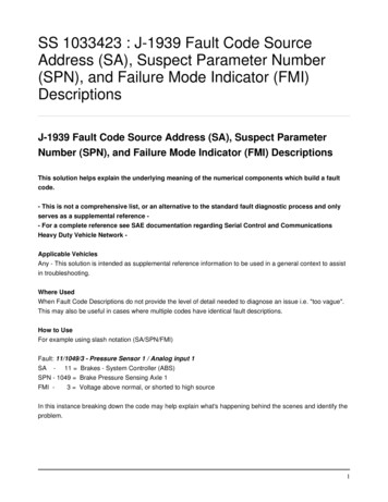
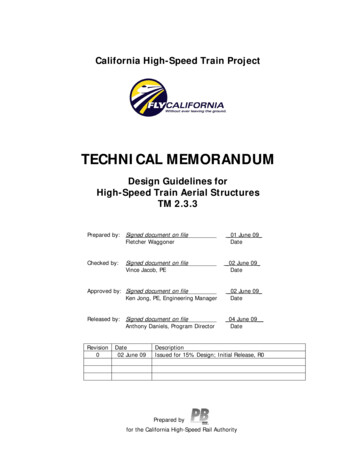
High-Speed Networks17 Physical level. It deals with the physical interface between an attached station(computer, terminal) and the link that attaches that station to the packet switchingnetwork. Physical level uses X.21 as well as other standards. Link level. It provides for the reliable transfer of data across the physical link bytransmitting the data as a sequence of frames. The link level standard is referred to asLAPB (Link Access Protocol – Balanced). Packet level. It provides a virtual circuit service that enables any subscribers to thenetwork to set up logical connections (virtual circuits) to other subscribers.Figure 2.1 depicts the user data and X.25 protocol control information. User data arepassed down to the X.25 packet level, which appends a header, creating a packet. Thepacket is then passed down to the link level, which appends a header and a trailer,forming a LAPB frame.Figure 2.1 User data and X.25 protocol control informationKey features of X.25 protocol: Call control packets, used for setting up and clearing virtual circuits, are carried onthe same channel and same virtual circuit as data packets. Multiplexing of virtual circuits takes place at layer 3. Both layer 2 and layer 3 include flow control and error control mechanisms.2.3. Frame Relay Networks2.3.1. Why Frame Relay? Overhead of X.25 approach associated with each node: Store data and organise them as a sequence of blocks. Add an X.25 header to each block to form a packet. Routing calculation. Form a LAPB frame from a frame by adding a LAPB header and a trailer. Transmit the frame to next node. Perform flow and error control functions when receiving a frame. Remove the data link layer fields and examine the packet header for routing purposes.This overhead is not justified in today’s reliable and high-quality networks.
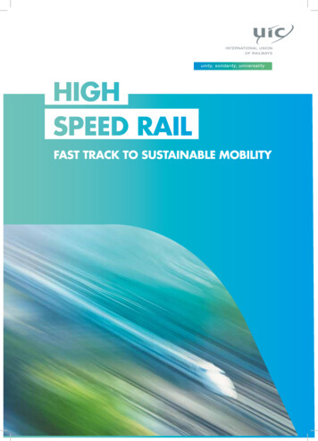
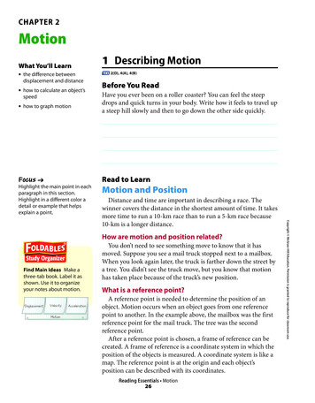
High-Speed Networks18Frame relay is designed to eliminate much of the overhead of X.25. The key differencebetween frame relay and a conventional X.25 packet-switching network are: Call control signaling is carried on a separate logical connection from user data. Multiplexing and switching of logical connection take place at layer 2 instead of layer3. There is no hop-by-hop flow control and error control.Frame relay can result in lower delay and higher throughput.2.3.2. Frame Relay ArchitectureFigure 2.2 shows the protocol stacks of frame relay and the comparison with X.25.Figure 2.2 Comparison of frame relay and X.25 protocols.Frame relay involves the physical layer and a data link control protocol known as LAPF(Link Access Protocol for Frame Mode Bearer Services).Frame relay involves the use of logical connections, called virtual connections. Aseparate virtual connection is devoted to call control. The setting up and tearing down ofvirtual connections is down over this permanent control-oriented virtual connection.Other virtual connections are used to carry data only.Frame relay significantly reduces the amount of work required of the network. However,error recovery is left to the higher layers since a frame in error is simply discarded.2.4. Congestion in Data Network and InternetsHow do congestions occur? Congestion occurs when the packets being transmitted through a network begins toapproach packet-handling capacity of the network. For each node (data network switch and router), there is a queue for each outgoingchannel.
High-Speed Networks 19As a rule of thumb, when a channel for which packets are queuing becomes morethan 80% utilised, it is an alarming rate of threshold.2.4.1. Effect of CongestionInput and output at a given node: Any given node has a number of I/O ports attached. There are 2 buffers at each port, one for arriving one to hold packets waiting todepart. Buffers can be of fixed-size or pool of memories available for all buffering activities. As a packet arrives, a node examines each incoming packet, and makes routingdecision. Then moves the packet to appropriate output buffer.Effects of congestion: If packets arrive faster than that they can be cleared from outgoing buffers, nomemory is available. Two general strategies: (1) discard those incoming packets for which there is noavailable buffer space; (2) apply a sort of flow control over its neighbors so that thetraffic flow remains manageable. But the neighbors also manage their queues, the congestion points can propagatethroughout a region or all of network.We need a flow control in such a way as to manage traffic on the entire network.2.4.2. Congestion ControlA number of congestion control techniques exist.Backpressure Similar to backpressure in fluids flowing down a pipe. The flow restriction at the end propagates backward (against flow of data traffic) tosources, which are restricted in flow of new packets into network. It is limited to connection-oriented network that allows hop-to-hop flow control (suchas X.25-based packet-switching networks provide this), neither ATM nor frame relayhas the capability. IP-based, there is no such facility for regulating the flow of data.Choke Packet It is a control packet generated at a congested node. It is transmitted back to a source node to restrict traffic. An example is the Internet Control Message Protocol (ICMP) Source Queunch(Message) packet (SQM).
High-Speed Networks20Implicit Congestion Signaling (ICS) Two phenomena in network congestion: (1) transmission delayed, and (2) packets arediscarded. Congestion control on the basis of implicit signaling is the responsibility of endsystems that requires all sources be able to detect congestion and reduce flow. ICS is efficient in connectionless, or datagram, configuration, IP-based internet.Explicit Congestion Signaling It typically operates over connection-oriented networks and controls the flow ofpackets over individual connections. Two directions:1. Backward: -- send alert bit or packets to source.2. Forward: -- send alert bit or packets to user then (to source). Three categories1. Binary: A bit is set in a data packet and is forwarded by congestion node.2. Credit based: These schemes are based on providing an explicit credit.3. Rate based: To control congestion, any node along the path of the connection canreduce data-rate2.4.3. Traffic ManagementThe following issues are related to the efficient use of a network at high load bycongestion control mechanisms: Fairness – As congestion develops, flows between sources and destinations willexperience increasing delay. Quality of Service (QoS) – packets may have the different requirements of delay, losssensitive, throughput etc. A node might transmit higher-priority packets ahead of lowpriority packets in the same queue. Reservations—is one way to avoid congestion (to provide assured service). Networkagrees to give a defined QoS as long as traffic flow is within contract parameters. Ifnet resources are inadequate to meet new reservation.2.5. Communication Protocol Architectures2.5.1. The OSI Protocol ArchitectureThe OSI (Open System Interconnection) Reference Model was developed by ISO(International Standards Organisation) as a model for implementing data communicationbetween cooperating systems. It has seven layers. Applic
High-Speed Networks 5 6. HIGH SPEED TRANSPORT-LEVEL TRAFFIC CONTROL.56 6.1. Study Points 56 6.2. Transmission Control Protocol 56 6.2.1. TCP Header Format 56 6.2.2. TCP Flow Control 57 6.2.3. Effect of Window Size on Performance 57 6.2.4. Adaptive Retransmission Timer 57 6.2.5. TCP Implementation Policy Options 58 6.3.