Transcription
NXP SemiconductorsUser GuideDocument identifier: UM11617Rev. 1, 07 September 2021MIMXRT1160-EVK Board User Manual
NXP SemiconductorsContentsChapter 1 Introduction. 31.1 Board overview.31.2 IMXRT1160 EVK board revision history. 41.3 IMXRT1160 EVK contents.41.4 Reference documentation. 41.5 EVK design files. 41.6 Acronyms and Abbreviations.41.7 PCB information. 51.8 Contents of evaluation kit. 6Chapter 2 Specifications. 72.1 Board pictures. 82.2 i.MX RT1160 processor.92.3 Boot mode configurations.92.4 Power tree. 102.5 SDRAM memory.132.6 SD card slot. 132.7 Hyper Flash. 132.8 QSPI Flash. 132.9 ENET PHY connector.132.10 USB PHY connector. 142.11 Audio input/output connector.142.12 OpenSDA circuit (DAP-Link). 142.13 JTAG connector.142.14 Arduino expansion port.152.15 Camera module connector. 162.16 User interface switch/button. 162.17 Sensor (DNP). 162.18 User interface LED indicator.162.19 LCD interface.16Chapter 3 Revision history.18MIMXRT1160-EVK Board User Manual, Rev. 1, 07 September 2021User Guide2 / 19
NXP SemiconductorsChapter 1IntroductionThis document is a Hardware User’s Guide for the IMXRT1160 Evaluation Kit (EVK) based on NXP's i.MX RT1160 processor.NXP Semiconductors fully supports this board. The User's Guide includes system setup and debugging. It provides detailedinformation on the overall design and usage of the EVK board from a hardware systems perspective.1.1 Board overviewThis EVK board is platform designed to showcase the most commonly used features of the i.MX RT1160 Processor in a small,low-cost package. The IMXRT1160 EVK board is an entry level development board, which gives developers an option to befamiliar with the processor before investing large amount or resources in more specific designs. For the Board Kit contents, referto Contents of evaluation kit.Table 1 lists the features of the IMXRT1160 EVK board.Table 1. Board featuresBoard ComponentProcessorDRAM MemoryDC-DCLDOSpecificationDetails of provider (if any)MIMXRT1166DVM6ANXP SemiconductorsW9825G6KH-5I * 2, 512 MB SDRAM, 200 MHzWinbondMP2143DJ, MP1613GTLMPSUM1750S-00,UNION, AMSUM1550S-28, AMS1117-1.8Mass StorageTF Card Slot128 Mbit Quad SPI Flash4 Mbit LPSPI Flash (DNP)2 Gbit Parallel NAND Flash (DNP)Display InterfaceEthernetUSBAudio ConnectorMIPI DSI LCD Connector10/100 Mbit/s Ethernet Connector. PHY Chip: KSZ8081RNBMicrochip Technology10/100/1000 Mbit/s Ethernet Connector. PHY Chip: RTL8211FDICGRealtekUSB 2.0 OTG Connector * 23.5 mm Audio Stereo Headphone JackBoard-Mounted MicrophoneLeft and Right Speaker Out ConnectorsS/PDIF Interface (DNP)Table continues on the next page.MIMXRT1160-EVK Board User Manual, Rev. 1, 07 September 2021User Guide3 / 19
NXP SemiconductorsIntroductionTable 1. Board features (continued)Board ComponentSpecificationPower Connector5 V DC-JackDebug ConnectorJTAG 20-pin Connector (SWD by default)Details of provider (if any)OpenSDA with DAP-LinkSensor (DNP)CameraCANUser Interface ButtonLED IndicatorExpansion PortPCBFXOS8700CQ: 6-Axis Encompass (3-Axis Mag, 3-Axis Accel)NXP SemiconductorsMIPI CSI InterfaceCAN Bus ConnectorON/OFF, POR Reset, Reset, USER ButtonPower Status, Reset, OpenSDA, USER LEDArduino Interface, M.2 interface5.1968 inch x 6.1024 inch (13.2 cm x 15.5 cm), 6-layer board1.2 IMXRT1160 EVK board revision history EVK REVA: Internal use, Alpha program, and product launch1.3 IMXRT1160 EVK contentsThe IMXRT1160 EVK contains the following items: IMXRT1160 EVK board 5 V power adapter USB cable (Micro B)1.4 Reference documentationBelow are listed the additional documents and resources that you can refer to for more information on the IMXRT1160 EVK board.Some of the documents listed below may be available only under a non-disclosure agreement (NDA). To request access to thesedocuments, contact your local NXP field applications engineer (FAE) or sales representative. IMXRT1160 EVK Quick Start Guide1.5 EVK design filesThe schematics, layout files, and Gerber files (including Silkscreen) can be downloaded from MIMXRT1160-EVK Product SupportPage on www.nxp.com.1.6 Acronyms and AbbreviationsThe following table lists the acronyms and abbreviations used in this document.MIMXRT1160-EVK Board User Manual, Rev. 1, 07 September 2021User Guide4 / 19
NXP SemiconductorsIntroductionTable 2. Acronyms and abbreviationsTermDescriptionADCAnalog-to-digital converterDACDigital-to-analog converterCANController Area NetworkCSICamera Serial InterfaceeMMCEmbedded Multimedia CardGPIOGeneral Purpose In/OutJTAGJoint Test Access Group (IEEE Std. 1149.1 )LDOLow Dropout RegulatorLEDLight Emitting DiodeMMCMultiMedia CardMSDMass Storage DevicePLLPhase-Locked LoopQSPIQuad Serial Peripheral InterfaceROMRead-Only MemoryRTCReal-time ClockSDSecure Digital CardSDHCSecure Digital High CapacitySRAMStatic Random Access MemorySDRAMSynchronous Dynamic Random-Access MemoryQSPIQueued/Quad Serial Peripheral InterfaceUARTUniversal Asynchronous Receiver/TransmitterUSBUniversal Serial Bus1.7 PCB informationThe IMXRT1160 EVK board uses the standard 6-layer technology. The material used is FR-4. The table below describes the PCBstack-up information.MIMXRT1160-EVK Board User Manual, Rev. 1, 07 September 2021User Guide5 / 19
NXP SemiconductorsIntroductionTable 3. Board stack-up informationLayerDescriptionCopper (Oz)Dielectric thickness ND1—Dielectric—3.5Signal1/2—1.8 Contents of evaluation kitTable 4. EVK contentsItemDescriptionEVK boardEVK board with processor, memory, interfaces, and so onPower adapter5V/3A power adapterUSB cableUSB cable, Micro-B to Standard-ANOTEMicro SD Card and LCD Module are not standard parts of the Evaluation Kit.MIMXRT1160-EVK Board User Manual, Rev. 1, 07 September 2021User Guide6 / 19
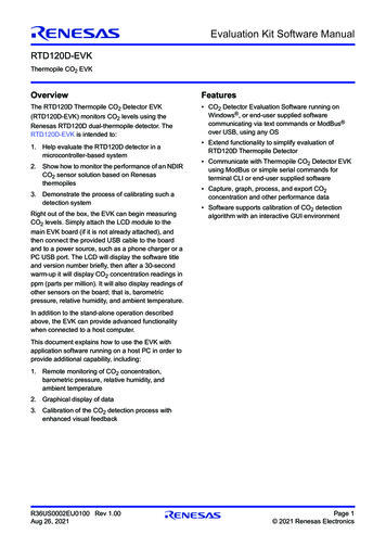
NXP SemiconductorsChapter 2SpecificationsThis chapter provides detailed information about the electrical design and practical considerations of the EVK board. Figure 1shows the block diagram of the IMXRT1160 EVK board. Board pictures are shown in the following section.Figure 1. Block diagram of the IMXRT1160EVK boardMIMXRT1160-EVK Board User Manual, Rev. 1, 07 September 2021User Guide7 / 19
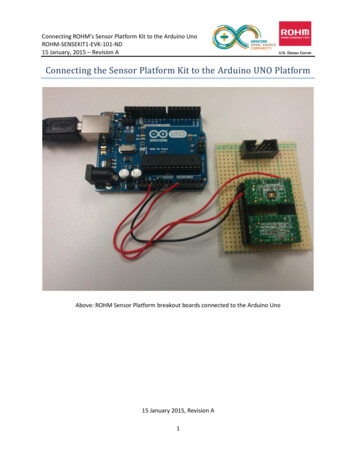
NXP SemiconductorsSpecifications2.1 Board pictures10/100MENETJTAGJTAG TraceCamera ModuleConnectorBootSwitch10/100/1000MENETM.2 SocketDebug USB PortArduino and MC InterfaceSD Card SocketSDRAMUSB OTG2MIMXRT1166ResetUSB OTG1 (SDP)Arduino and MC InterfacePower on ResetAudio Jack5 V DC IN SwitchPower Jumper5 V DC INCPU WakeupButtonMIC ArrayExtensionCPU ON/OFFButtonOctalFlashMICaaa-041705Figure 2. Overview of the IMXRT1160 EVK board (Front side)MIMXRT1160-EVK Board User Manual, Rev. 1, 07 September 2021User Guide8 / 19
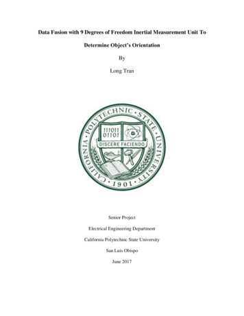
NXP SemiconductorsSpecificationsMIPI LCD ConnectorQSPI FlashFigure 3. Overview of the IMXRT1160 EVK board (Back side)2.2 i.MX RT1160 processor The i.MX RT1160 is a new processor family featuring NXP's advanced implementation of the high performance Arm Cortex RM7 Core and power efficient Arm CortexR-M4 Core. It provides high CPU performance and best real-time response.The i.MX RT1160 has 2 MB on-chip RAM in total, including a 512 kB RAM which can be flexibly configured as TCM orgeneral-purpose on-chip RAM. The i.MX RT1160 integrates advanced power management module with DC-DC and LDO thatreduces complexity of external power supply and simplifies power sequencing.It provides various memory interfaces, including SDRAM, Raw NAND FLASH, NOR FLASH, SD/eMMC, Quad SPI, HyperRAM/Flash. It also provides a wide range of other interfaces for connecting peripherals, such as WLAN, BluetoothR, GPS,displays, and camera sensors. Like other i.MX processors, i.MX RT1160 also has rich audio and video features, including MIPICSI/DSI, LCD display, graphics accelerator, camera interface, S/PDIF, and I2S audio interface.The i.MX RT1160 applications processor can be used in areas such as industrial HMI, IoT, high-end audio appliance, low-endinstrument cluster, motor control, and home appliances.2.3 Boot mode configurationsThe device has four boot modes, with one reserved for NXP use. The boot mode is selected based on the binary value stored in theinternal BOOT MODE register. Switches (SW1-3 and SW1-4) are used to select the boot mode on the IMXRT1160 EVK board.MIMXRT1160-EVK Board User Manual, Rev. 1, 07 September 2021User Guide9 / 19
NXP SemiconductorsSpecificationsTable 5. Boot mode pin settingsBOOT MODE[1:0]BOOT type(SW1-3 SW1-4)00Boot from fuses01Serial downloader10Internal boot11ReservedTypically, the internal boot is selected for normal boot, which is configured by external BOOT CFG GPIOs. The table below showsthe typical boot mode and boot device settings.Table 6. Typical boot modes and boot device settingsSW1-3SW1-4SW2-3SW2-6SW2-7Boot device011000SDP mode10000QSPI Flash10100OCT Flash10010NAND Flash10001SD card1. Switch value is not described if the option remains 0 for different boot device.NOTEFor more information about Boot mode configuration, refer to the "System Boot" Chapter in MIMXRT1160Reference Manual.For more information about IMXRT1160 EVK boot device selection and configuration, refer to theBoard Schematic.2.4 Power treeSpecificationsA DC 5 V external power supply is used to supply the IMXRT1160 EVK board at J43, and a slide switch SW5 is used to turnthe power ON/OFF. J20 and J11 can also be used to supply the EVK Board. Different power supplies need to configure differentJumper setting of J38. The table below lists the details.Table 7. Jumper settings of power supplyPower supplyJ38 settingsJ431-2J203-4J115-6MIMXRT1160-EVK Board User Manual, Rev. 1, 07 September 2021User Guide10 / 19
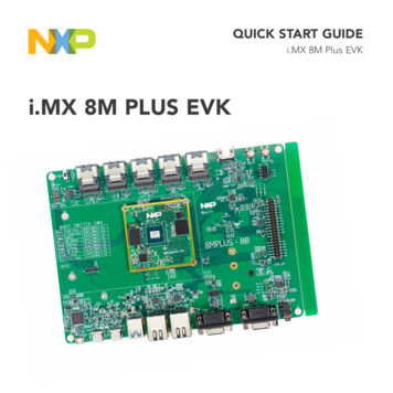
NXP SemiconductorsSpecificationsNOTEFor some use cases, the power consumption is larger than 500 mA@5V. For such cases, it is recommended to usea DC adapter that can support up to 3 A.Figure 4 shows the power tree.Figure 4. Power tree Power-on sequence requirements:— VDD SNVS IN supply must be turned on before any other power supply, or be connected (shorted) withVDD LPSR INand DCDC IN supply.— If a coin cell is used to power VDD SNVS IN, ensure that it is connected before any other supply is switched on.— When internal DC-DC is enabled, external delay circuit is required to delay the DCDC PSWITCH signal 1 ms afterDCDC IN is stable.— The POR B input, if used, must be immediately asserted at power-on and remain asserted until after the last powerrail reaches its working voltage. In the absence of an external reset feeding the POR B input, the internal PORmodule takes control. Power-off sequence requirements:— VDD SNVS IN supply must be turned off after any other power supply, or be connected (shorted) with VDD LPSR INand DCDC IN supply.— If a coin cell is used to power VDD SNVS IN, ensure that it is removed after any other supply is switched off.MIMXRT1160-EVK Board User Manual, Rev. 1, 07 September 2021User Guide11 / 19
NXP SemiconductorsSpecificationsFigure 5. Power-on and power-off sequenceThe figure below shows the power control logic of the IMXRT1160 EVK board. It powers up SNVS first, then PMIC ON REQ is switched on to enable external DC-DC to power up other power domains. ON/OFF button is used to switch ON/OFF PMIC ON REQ to control power modes. The RESET button and WDOG output are used to reset the system power.Figure 6. The power control logic of the IMXRT1160 EVK boardThe table below describes the power rails on the board.MIMXRT1160-EVK Board User Manual, Rev. 1, 07 September 2021User Guide12 / 19
NXP SemiconductorsSpecificationsTable 8. Power railsPower railMin (V)Typ (V)Max (V)DescriptionDCDC IN33.33.6Power for DC-DCVDDA 1P8 IN1.711.81.89Power for PLL, OSC, and LDOsVDD SOC IN0.71.01.155Power for digital logicsVDD LPSR IN33.33.6Power for LPSR domainVDD SNVS IN2.433.6Power for SNVS and RTCVDD USB 1P81.651.81.95Power for USB OTG PHYsVDD USB 3P333.33.6VDD ADC 1P81.651.81.95VDD ADC 3P333.33.6VDD MIPI 1P81.651.81.95Power for MIPI CSI/DSI PHYVDD MIPI 1P00.91.01.1Power for MIIPI CSI/DSI PHYPower for ADC, Power for DAC andACMP, ADC VREFH VDDA ADC 1P8 2.5 SDRAM memoryTwo 256 MB, 200 MHz SDRAM (W9825G6KH-5I) is used on the EVK Board.2.6 SD card slotThere is an SD card slot (J15) on the IMXRT1160 EVK board. J15 is the Micro SD slot for USDHC1 interface. If the developerwants to boot from the SD Card, the boot device switch settings should be set correctly as shown in Table 6.2.7 Hyper FlashSpecificationsOn the IMXRT1160 EVK board, there is one 512 Mbit Hyper Flash device. If the developer wants to boot from the Hyper Flash,the boot device switch settings should be set correctly as shown in Table 6.By default, the Hyper Flash is not used. To enable the onboard OCT Flash, the settings must be changed.1. Remove resistors: R380/R399/R386/R390/R392/R385.2. Weld 0 Ω resistors: R381/R378/R382/R389/R402/R377/R388/R391.2.8 QSPI FlashA 128 Mbit QSPI Flash is used on the IMXRT1160 EVK board. If the developer wants to boot from the QSPI Flash, the boot deviceswitch settings should be set correctly as shown in Table 6.By default, this QSPI Flash is enabled on the EVK.2.9 ENET PHY connectorThere are two Ethernet Mac controllers in the MIMXRT1160 processor.MIMXRT1160-EVK Board User Manual, Rev. 1, 07 September 2021User Guide13 / 19
NXP SemiconductorsSpecificationsThe 10/100 M Ethernet subsystems of the IMXRT1160 EVK board are provided by the KSZ8081RNB 10/100 M Ethernettransceiver (U7) and an RJ45 (J3) with integrated magnetic.The 10/100/1000 M Ethernet subsystems of the IMXRT1160 EVK board are provided by the RTL8211FDI-CG 10/100/1000 MEthernet transceiver (U10) and an RJ45 (J4) with integrated magnetic.2.10 USB PHY connectorThe MIMXRT1160 contains two integrated USB 2.0 PHYs capable of connecting to USB host/device systems at the USBlow-speed (LS) rate of 1.5 Mbits/s, full-speed (FS) rate of 12 Mbits/s or at the USB 2.0 high-speed (HS) rate of 480 Mbits/s.2.11 Audio input/output connectorThe audio CODEC used on the IMXRT1160 EVK board is Wolfson’s low-power, high-quality Stereo Codec, WM8960. TheIMXRT1160 EVK board includes:1. One headphone interface (J33), which is a 3.5 mm audio stereo headphone jack that supports jack detection.2. One on-board MIC (P1).3. Two speaker interfaces (J39, J40).The EVK also provides the SPDIF interface (J45 and J46, DNP) and DMIC interface input through U40/U41/U44/U45.2.12 OpenSDA circuit (DAP-Link)The OpenSDA circuit (CMSIS–DAP) is an open-standard serial and debug adapter. It bridges serial and debug communicationsbetween a USB host and an embedded target processor.CMSIS-DAP features a Mass Storage Device (MSD) bootloader, which provides a quick and easy mechanism for loading differentCMSIS-DAP Applications such as flash programmers, run-control debug interfaces, serial-to-USB converters, etc. Two or moreCMSIS-DAP applications can run simultaneously. For example, run-control debug application and serial-to-USB converter runin parallel to provide a virtual COM communication interface while allowing code debugging via CMSIS-DAP with just a singleUSB connection.For the IMXRT1160 EVK board, J11 is the connector between the USB host and the target processor. Jumper to serial downloadermode uses the stable DAP-Link debugger function. If developer wants to make OpenSDA going to the bootloader mode, jumperJ27 to 1-2 and press SW3 when powering it on. Meanwhile, the OpenSDA supports drag/drop feature for U-Disk.1. Use the serial downloader mode to drag/drop the image file to U-Disk.2. Select QSPI Flash as boot device.3. Reset the board.Now the image runs.2.13 JTAG connectorJ1 is a standard 20-pin/2.54 mm box header connector for JTAG. Figure 7 shows the pin definitions. SWD is supported by default.MIMXRT1160-EVK Board User Manual, Rev. 1, 07 September 2021User Guide14 / 19
NXP SemiconductorsSpecificationsFigure 7. JTAG pin definitionsNOTEBy default, the RT1160 silicon can use both SWD and JTAG modes using the Arm stitching sequence. For theRT1160 EVK board, SWD debug is used by default without any board modification. To use JTAG debug, solderout R187, R208, R195, and R78, because some JTAG signals are multiplexed with other functions.2.14 Arduino expansion portJ22 to J25 are defined as Arduino interfaces. The table below lists the pin definitions of Arduino interfaces.Table 9. Arduino interface pin definitionsJ9J26J10J25UART RX/D0A0/ADC0D8/CLKO/ICP1NCUART TX/D1A1/ADC1D9/OC1A/PWMIOREFD2/INT0A2/ADC2D10/SPI CSRESETD3/INT1/PWM/OC2BA3/ADC3D11/OC2A/PWM/SPI MOSI3.3 VD4/T0/XCKA4/ADC4/SDAD12/SPI MISO5VD5/TI/PWMA5/ADC5/SCLD13/SPI IN——D14/I2C SDA———D15/I2C SCL—MIMXRT1160-EVK Board User Manual, Rev. 1, 07 September 2021User Guide15 / 19
NXP SemiconductorsSpecifications2.15 Camera module connectorThe i.MX RT1160 EVK board supports one MIPI CSI. There is a Camera Module Connector (J2) on the IMXRT1160 EVK board.The MT9M114 based on OV5640 can be used directly.2.16 User interface switch/buttonThere are four user interface switches/buttons on the IMXRT1160 EVK board. Their functionalities are as below.2.16.1 Power switchSW5 is a slide switch to control the power of the IMXRT1160 EVK board when the power supply is from J43. The functions of thisswitch are listed as below: Sliding the switch to the ON position connects the 5 V power supply to the Evaluation board main power system. Sliding the switch to the OFF position immediately removes all power from the board.2.16.2 ON/OFF buttonSW6 is the ON/OFF button for IMXRT1160 EVK board. A short pressing in the OFF mode causes the internal powermanagement state machine to change state to ON. In the ON mode, a short pressing generates an interrupt, intended to be asoftware-controllable (power-down). Pressing for approximate five seconds or longer causes a forced OFF. Both boot mode inputscan be disconnected.2.16.3 Reset buttonThere are two reset buttons on the EVK board. SW4 is the power-on reset button. Pressing the SW4 in the ON state forces reseton the system power except for SNVS domain. The processor is immediately turned off and a boot cycle from the OFF state isreinitiated. SW3 is the POR pin reset button.2.16.4 USER buttonSW7 is the USER button connected to the WAKEUP pin for developer to use.2.17 Sensor (DNP)U34 on the EVK board is a 6-Axis Ecompass, 3-Axis Magnetometer, 3-Axis Accelerator, and sensor FXOS8700CQ. TheEcompass is connected to I2C5 port of i.MX RT1160.2.18 User interface LED indicatorThere are four LED status indicators on the EVK board. The functions of these LEDs include: Main power supply(D16)— Green: DC 5 V main supply is normal.— Red: J2 input voltage is over 5.6 V.— Off: the board is not powered. POR pin Reset RED LED (D7) USER LEDs (D6, D34)2.19 LCD interfaceThe Mobile Industry Processor Interface (MIPI) Display Serial Interface (DSI) controller is a flexible digital core, with highperformance and easy to use. It implements all protocol functions defined in the MIPI DSI specification. The MIPI DSI controllerprovides an interface that allows communication with MIPI DSI-compliant peripherals.MIMXRT1160-EVK Board User Manual, Rev. 1, 07 September 2021User Guide16 / 19
NXP SemiconductorsSpecificationsIf developers want to use LCD, NXP provides an optional LCD module RK055HDMIPI4M equipped with a 5.5” 720*1280 TFT LCDdisplay with touch sensitive overlay. This module contains one FPC cable that connects to RT1160 EVK. The LCD interface canbe connected to J48. LCD modules can be purchased from the NXP website.MIMXRT1160-EVK Board User Manual, Rev. 1, 07 September 2021User Guide17 / 19
NXP SemiconductorsChapter 3Revision historyTable 10. Revision historyRevision numberDateSubstantive changes107 September 2021Deleted the MIPI CAMERA MODULE and DNP sensor025 May 2021Initial public releaseMIMXRT1160-EVK Board User Manual, Rev. 1, 07 September 2021User Guide18 / 19
How To Reach UsHome Page:nxp.comWeb Support:nxp.com/supportInformation in this document is provided solely to enable system and software implementers to use NXP products. Thereare no express or implied copyright licenses granted hereunder to design or fabricate any integrated circuits based on theinformation in this document. NXP reserves the right to make changes without further notice to any products herein.NXP makes no warranty, representation, or guarantee regarding the suitability of its products for any particular purpose, nordoes NXP assume any liability arising out of the application or use of any product or circuit, and specifically disclaims anyand all liability, including without limitation consequential or incidental damages. “Typical” parameters that may be providedin NXP data sheets and/or specifications can and do vary in different applications, and actual performance may vary overtime. All operating parameters, including “typicals,” must be validated for each customer application by customer's technicalexperts. NXP does not convey any license under its patent rights nor the rights of others. NXP sells products pursuant tostandard terms and conditions of sale, which can be found at the following address: nxp.com/SalesTermsandConditions.Right to make changes - NXP Semiconductors reserves the right to make changes to information published in thisdocument, including without limitation specifications and product descriptions, at any time and without notice. Thisdocument supersedes and replaces all information supplied prior to the publication hereof.Security — Customer understands that all NXP products may be subject to unidentified or documented vulnerabilities.Customer is responsible for the design and operation of its applications and products throughout their lifecycles to reducethe effect of these vulnerabilities on customer’s applications and products. Customer’s responsibility also extends to otheropen and/or proprietary technologies supported by NXP products for use in customer’s applications. NXP accepts noliability for any vulnerability. Customer should regularly check security updates from NXP and follow up appropriately.Customer shall select products with security features that best meet rules, regulations, and standards of the intendedapplication and make the ultimate design decisions regarding its products and is solely responsible for compliance with alllegal, regulatory, and security related requirements concerning its products, regardless of any information or support thatmay be provided by NXP. NXP has a Product Security Incident Response Team (PSIRT) (reachable at PSIRT@nxp.com)that manages the investigation, reporting, and solution release to security vulnerabilities of NXP products.NXP, the NXP logo, NXP SECURE CONNECTIONS FOR A SMARTER WORLD, COOLFLUX,EMBRACE, GREENCHIP,HITAG, ICODE, JCOP, LIFE, VIBES, MIFARE, MIFARE CLASSIC, MIFARE DESFire, MIFARE PLUS, MIFARE FLEX,MANTIS, MIFARE ULTRALIGHT, MIFARE4MOBILE, MIGLO, NTAG, ROADLINK, SMARTLX, SMARTMX, STARPLUG,TOPFET, TRENCHMOS, UCODE, Freescale, the Freescale logo, AltiVec, CodeWarrior, ColdFire, ColdFire , the EnergyEfficient Solutions logo, Kinetis, Layerscape, MagniV, mobileGT, PEG, PowerQUICC, Processor Expert, QorIQ, QorIQQonverge, SafeAssure, the SafeAssure logo, StarCore, Symphony, VortiQa, Vybrid, Airfast, BeeKit, BeeStack, CoreNet,Flexis, MXC, Platform in a Package, QUICC Engine, Tower, TurboLink, EdgeScale, EdgeLock, eIQ, and Immersive3D aretrademarks of NXP B.V. All other product or service names are the property of their respective owners. AMBA, Arm, Arm7,Arm7TDMI, Arm9, Arm11, Artisan, big.LITTLE, Cordio, CoreLink, CoreSight, Cortex, DesignStart, DynamIQ, Jazelle,Keil, Mali, Mbed, Mbed Enabled, NEON, POP, RealView, SecurCore, Socrates, Thumb, TrustZone, ULINK, ULINK2,ULINK-ME, ULINK-PLUS, ULINKpro, μVision, Versatile are trademarks or registered trademarks of Arm Limited (or itssubsidiaries) in the US and/or elsewhere. The related technology may be protected by any or all of patents, copyrights,designs and trade secrets. All rights reserved. Oracle and Java are registered trademarks of Oracle and/or its affiliates. ThePower Architecture and Power.org word marks and the Power and Power.org logos and related marks are trademarks andservice marks licensed by Power.org. NXP B.V. 2021.All rights reserved.For more information, please visit: http://www.nxp.comFor sales office addresses, please send an email to: salesaddresses@nxp.comDate of release: 07 September 2021Document identifier: UM11617
This document is a Hardware User's Guide for the IMXRT1160 Evaluation Kit (EVK) based on NXP's i.MX RT1160 processor. NXP Semiconductors fully supports this board. The User's Guide includes system setup and debugging. It provides detailed information on the overall design and usage of the EVK board from a hardware systems perspective.