Transcription
Evaluation Kit Software ManualRTD120D-EVKThermopile CO2 EVKOverviewFeaturesThe RTD120D Thermopile CO2 Detector EVK(RTD120D-EVK) monitors CO2 levels using theRenesas RTD120D dual-thermopile detector. TheRTD120D-EVK is intended to: CO2 Detector Evaluation Software running onWindows , or end-user supplied softwarecommunicating via text commands or ModBus over USB, using any OS1. Help evaluate the RTD120D detector in amicrocontroller-based system2. Show how to monitor the performance of an NDIRCO2 sensor solution based on Renesasthermopiles3. Demonstrate the process of calibrating such adetection systemRight out of the box, the EVK can begin measuringCO2 levels. Simply attach the LCD module to themain EVK board (if it is not already attached), andthen connect the provided USB cable to the boardand to a power source, such as a phone charger or aPC USB port. The LCD will display the software titleand version number briefly, then after a 30-secondwarm-up it will display CO2 concentration readings inppm (parts per million). It will also display readings ofother sensors on the board; that is, barometricpressure, relative humidity, and ambient temperature. Extend functionality to simplify evaluation ofRTD120D Thermopile Detector Communicate with Thermopile CO2 Detector EVKusing ModBus or simple serial commands forterminal CLI or end-user supplied software Capture, graph, process, and export CO2concentration and other performance data Software supports calibration of CO2 detectionalgorithm with an interactive GUI environmentIn addition to the stand-alone operation describedabove, the EVK can provide advanced functionalitywhen connected to a host computer.This document explains how to use the EVK withapplication software running on a host PC in order toprovide additional capability, including:1. Remote monitoring of CO2 concentration,barometric pressure, relative humidity, andambient temperature2. Graphical display of data3. Calibration of the CO2 detection process withenhanced visual feedbackR36US0002EU0100 Rev 1.00Aug 26, 2021Page 1 2021 Renesas Electronics
RTD120D-EVK Evaluation Kit Software ManualContents1.Connection Modes . . . . . . . . . . . . . . . . . . . . . . . . . . . . . . . . . . . . . . . . . . . . . . . . . . . . . . . . . . . . . . . . . . . 21.11.22.ModBus Mode . . . . . . . . . . . . . . . . . . . . . . . . . . . . . . . . . . . . . . . . . . . . . . . . . . . . . . . . . . . . . . . . . . . 2Terminal Mode . . . . . . . . . . . . . . . . . . . . . . . . . . . . . . . . . . . . . . . . . . . . . . . . . . . . . . . . . . . . . . . . . . . 2ModBus Example: DAQFactory . . . . . . . . . . . . . . . . . . . . . . . . . . . . . . . . . . . . . . . . . . . . . . . . . . . . . . . . . 42.12.22.32.42.5Installing DAQFactory Express . . . . . . . . . . . . . . . . . . . . . . . . . . . . . . . . . . . . . . . . . . . . . . . . . . . . . .Board Connections . . . . . . . . . . . . . . . . . . . . . . . . . . . . . . . . . . . . . . . . . . . . . . . . . . . . . . . . . . . . . . .Establishing a Connection with the EVK . . . . . . . . . . . . . . . . . . . . . . . . . . . . . . . . . . . . . . . . . . . . . . .Monitoring CO2 Concentration and Sensor Readings . . . . . . . . . . . . . . . . . . . . . . . . . . . . . . . . . . . . .Calibration Using DAQFactory . . . . . . . . . . . . . . . . . . . . . . . . . . . . . . . . . . . . . . . . . . . . . . . . . . . . . .2.5.1General Calibration Principles . . . . . . . . . . . . . . . . . . . . . . . . . . . . . . . . . . . . . . . . . . . . . . .2.5.2Calibration Procedure . . . . . . . . . . . . . . . . . . . . . . . . . . . . . . . . . . . . . . . . . . . . . . . . . . . . . .45577783.Appendix A: Background Information . . . . . . . . . . . . . . . . . . . . . . . . . . . . . . . . . . . . . . . . . . . . . . . . . . . 134.Appendix B: Terminal Mode Commands . . . . . . . . . . . . . . . . . . . . . . . . . . . . . . . . . . . . . . . . . . . . . . . . . 145.Revision History . . . . . . . . . . . . . . . . . . . . . . . . . . . . . . . . . . . . . . . . . . . . . . . . . . . . . . . . . . . . . . . . . . . . 171.Connection ModesThe EVK supports two modes of operation when connected to a host computer. Both modes, ModBus mode andterminal mode use the same USB connection. When the EVK powers up, it immediately operates as astand-alone CO2 detector as described in the RTD120D-EVK CO2 EVK User Manual, with the integrated LCD andpush-button switches acting as the primary user interface. In the background, the USB interface is continuallymonitored for an incoming connection. When a USB connection takes place, the first data byte received from thehost computer determines which protocol will be used.If the first byte is binary 0, 1, 2, 3, 4, 5, 6, or 7, it assumes a ModBus client is attempting to talk to it. When thisoccurs, the EVK operates in ModBus mode until the next re-start. Acting as a ModBus agent, that byte and allsubsequent received bytes are separated into packets and interpreted as ModBus requests. If the first byte isanything other than binary 0, 1, 2, 3, 4, 5, 6, or 7, it is assumed to be part of a text command. The remaining bytesare interpreted as characters of a text command, and the EVK operates in terminal mode until the next re-start.Regardless of the communication modes (ModBus mode or terminal mode), the EVK continues to execute thesame algorithms and support the LCD/push-button user interface, even while a host computer is interacting withthe kit using one of these two protocols.1.1ModBus ModeAny ModBus client running on a Windows, Linux, or Mac host computer can be used as long as the client isconfigured to use the ModBus RTU protocol over USB. To get up and running quickly using ModBus, support filesare provided for using the DAQFactory Express application by AzeoTech , which can be downloaded for free(see Installing DAQFactory Express). These support files can be downloaded from the RTD120D-EVK’s productpage under “software”, and they configure the GUI for various use cases, such as to show live graphs of sensorreadings and related variables, and to provide a set of controls and graphs for an enhanced calibration userexperience.1.2Terminal ModeIn terminal mode, text commands can be sent over USB from a terminal program or a user’s application which canbe written in any language and framework that supports serial communication.R36US0002EU0100 Rev 1.00Aug 26, 2021Page 2
RTD120D-EVK Evaluation Kit Software ManualText commands are simple, one-line strings that are terminated by a carriage return. These commands can beused to interrogate and stream data from the board and to perform various functions. An example of a textcommand is “ ppm CR ”. Note that the CR is a single carriage return character, so you just need to type ppm and then press Enter on the keyboard. A terminal program, such as Putty or Tera Term, can be used tointeract with the EVK in this mode. In order to allow strings of characters to be pasted into such a terminalprogram without any data loss, Renesas recommends to configure a 5 millisecond delay between sent charactersin the terminal program’s settings. For example, in Tera Term, the following setup works reliably when pasting textinto the terminal window (MENU: Setup - Serial Port.)Terminal mode does not echo characters as they are received. This is to make it easier to write host applicationsthat use the terminal mode, without having to distinguish between echoed characters and information responses.As such, to make it easier to type interactively when using a terminal program, you may find it preferable to enable“local echo” in the terminal program’s configuration settings. In Tera Term, this is how it is (MENU: Setup Terminal.)R36US0002EU0100 Rev 1.00Aug 26, 2021Page 3
RTD120D-EVK Evaluation Kit Software ManualNote: Terminal mode uses a “stateless” command line interface model, meaning, all commands are available at alltimes. This is in contrast to a multi-level, menu-driven command line interface, where the available commandsdepend on commands that have already been executed. The stateless model was chosen as it is moreconvenient for applications created by the end user, or simple extensions to data processing systems such asMatLab, where a program running on the host computer must be able to access all commands without thecomplexity of keeping track of the state of the interface. As a basic example, a python script that needs to accessvarious bits of data from the EVK can simply call an interrogation function to read a parameter or sensor readingwhenever it needs to.Commands are not case-sensitive, so “start ppm” is equivalent to “START PPM” and to “Start PPM”, etc.The available commands include interrogation commands, starting with “ ” (such as “ PPM”), parameter settingcommands starting with “set“ (such as “set S1 RAW 1234.56“ and “set FILTER ADC”), and “FORCE COIL”commands starting with “!”. FORCE COIL commands are simple commands with low communications overhead,using the ModBus FORCE COIL primitive.For a list of supported commands, see Appendix B: Terminal Mode Commands.2.ModBus Example: DAQFactoryThe Thermopile CO2 Detector Software consists of data acquisition software (DAQFactory Express, availablefrom AzeoTech) and “control” files that configure DAQFactory to be used with the Thermopile CO2 Detector EVK.The control files are available for download from the RTD120D-EVK product page. When opened by DAQFactory,these control files provide useful functionality without modification but they can also be customized by the user tochange and add functionality. New control files can also be created from scratch; however, for the beginner user, itis easier to use one of the provided control files and just modify it instead of creating one from scratch. To do this,save one of the provided control files under a new name and then modify the file in order as not to lose the originalcapability.DAQFactory is a data acquisition and processing platform that can communicate using the ModBus RTU protocol,over a USB serial connection transport. It provides a GUI that can be used to monitor and process real-time datastreaming from the evaluation board. Actions can also be initiated from the GUI to cause operations on the EVK tobe carried out, such as adjusting filter settings and saving calibration data points.The free version, “DAQFactory Express”, has all the functionality needed to access basic features of the EVK,including monitoring readings of CO2, viewing intermediate variables, calibrating the CO2 detection algorithm, andmonitoring the temperature, relative humidity, and barometric pressure from the other sensors on the EVK.The DAQFactory “control” files (with extension .ctl) contain GUI screen definitions, application-specificcommunication settings, and scripts for various purposes. The control files for use with the EVK can bedownloaded from the RTD120D-EVK product page. Opening a control file in DAQFactory is all that is needed tostart using the GUI with the EVK for control, monitoring and calibrating.2.1Installing DAQFactory ExpressTo install DAQFactory Express, go to the AzeoTech website and download version 18.1 or later of DAQFactoryExpress. This will install an “Evaluation” version of the full DAQFactory application, as well as the “Express”version, which has no time limit but some functionality is limited.For basic monitoring and visualization (plotting) of on-board sensors and system parameters, as well ascalibration of the CO2 algorithm and miscellaneous control of the EVK, the “Express” version of DAQFactory hasall the necessary functionality. Other applications that can act as a ModBus RTU master over USB can also beused. This is supported by the EVK’s firmware, but additional configuration is required that is specific to thedesired ModBus application.Note: After installing DAQFactory, either version can be run from the Start menu; however, Renesas recommendsrunning the Express version because it does not have a time limit. If you require more capability beyond the needsR36US0002EU0100 Rev 1.00Aug 26, 2021Page 4
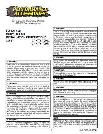
RTD120D-EVK Evaluation Kit Software Manualof the RTD120D-EVK, you can later purchase one of the more full-featured versions of DAQFactory directly fromAzeoTech. (DAQFactory and AzeoTech are registered trademarks of AzeoTech, Inc. Renesas has no affiliationwith AzeoTech.)2.2Board ConnectionsA USB (B-micro) connector is used to power the board and for communications with a host computer. For thecurrent purposes, you only need to connect the USB cable. However, there is also an auxiliary power connector(not needed for normal operation), two jumper headers to facilitate firmware updates (updating the applicationsoftware that comes pre-loaded on the EVK), and a programming/debug interface using two different connectoroptions. The programming/debug interface can be used to support developing custom firmware to run on the EVK,using Renesas Flexible Software Package (FSP) and the Renesas e2studio Eclipse-based IDE. For moreinformation, contact Renesas Technical Support.2.3Establishing a Connection with the EVKAfter installing DAQFactory Express, connect the USB cable to the EVK and to a USB port on your PC. StartDAQFactory Express from the Windows Start Menu. Note that both the full and Express versions are availableafter installation. Using the Express version allows you to use the platform without a time limit.1. With DAQFactory Express running, open the control file provided by Renesas called “monitor.ctl”. Next, selectthe COM port for use with the EVK as follows:Figure 1. Menu: Quick - Device Configuration - ModbusCOM - Select - ConfigureR36US0002EU0100 Rev 1.00Aug 26, 2021Page 5
RTD120D-EVK Evaluation Kit Software Manual2. In the Serial Port Configuration dialog, set Serial Port # (COM) to the port number the EVK is connected to(e.g., 4 for COM4). To determine the correct COM port number, you may need to open Device Manager fromthe Windows Start menu to observe which COM port appears in response to connecting the USB cablebetween the kit and your PC. This port number is remembered whenever you save the control file, so it willmost likely already be correct if you recently connected to the same EVK on this port.3. Click “Save”, then click “OK”. Communication between DAQFactory and the EVK will start automatically. If yousubsequently disconnect and re-connect the EVK from your PC, then you must complete the following to reestablish communication:a. Open the Communications Monitor viewMENU: View - Comm Monitorb. Right-click in the view and select Configure.c.Click Save.R36US0002EU0100 Rev 1.00Aug 26, 2021Page 6
RTD120D-EVK Evaluation Kit Software Manual2.4Monitoring CO2 Concentration and Sensor ReadingsAfter communication is established, the GUI will display live graphs of the CO2 Concentration and readings of theother sensors on the board. To manipulate the scale and depth of the data displayed in these graphs, refer to theDAQFactory help guides, which can be accessed from the Help menu.2.5Calibration Using DAQFactoryThe EVK is pre-calibrated but it can be re-calibrated if desired. Calibration can be performed in either of two ways: In a stand-alone fashion, using the LCD and push-button user interface on the EVK itself With a GUI, using a connected PC for a more interactive and visual experienceThis section describes the GUI-based method of CO2 calibration. To calibrate the kit without using a connectedhost computer (instead using the LCD and pushbutton UI), see the RTD120D-EVK CO2 EVK User Manual.2.5.1General Calibration PrinciplesThe EVK continuously reads the two thermopile channels, reading each channel once with the lamp ON and oncewith the lamp OFF, resulting in four readings. After each such sequence, a “raw” value (a positive integer typicallybetween a few hundred and a few thousand) is calculated from the four readings. The sequence occurs every5 seconds, so a “raw” value is always available in the microcontroller’s memory to be used for further processing,R36US0002EU0100 Rev 1.00Aug 26, 2021Page 7
RTD120D-EVK Evaluation Kit Software Manualsuch as for calculating CO2 concentration or calibrating the kit so that accurate CO2 concentration determinationis possible.Calibration consists of allowing various gas mixtures of known CO2 concentration to enter the gas chamber(where CO2 concentration is measured), and storing in memory the resulting “raw” values that result from thosegas mixtures, associating those values with the known CO2 concentration of each gas. For example, gas with noCO2 (concentration of 0 ppm) results in a raw value that gets stored in a variable “raw 1”, gas with a CO2concentration of 1000 ppm results in another raw value that gets stored in a variable “raw 2”, and so on. At leastthree such values must be stored: raw 1, raw 2, and raw 3 corresponding to CO2 concentrations of 0ppm,1000ppm, and 400ppm, respectively. For more accuracy in ranges above 1000ppm, a fourth raw value (raw 4)can optionally be stored as well, which corresponds to a CO2 concentration of 2000ppm. These three or four rawvalues get stored in flash memory, and are used later when the kit is determining CO2 concentration of unknowngases (such as ambient air in the vicinity of the kit). This is done by computing raw readings and applying afunction that interpolates the CO2 concentration from the known concentrations associated with the stored rawvalues.2.5.2Calibration ProcedureWhen the EVK is used with DAQFactory running on a PC, real-time display of a graph of CO2 concentration andother kit parameters can be viewed. That data can also be processed, analyzed, and logged for further processingand use with other tools.A useful capability provided by the GUI is to allow the calibration procedure to be performed in a more interactive,visual manner. For this, a control file must be loaded by DAQFactory which defines user-interface elements suchas live graphs and buttons to aid in performing calibration.From DAQFactory, open the control file “calibrate.ctl”. This file is included in the GUI download from theRTD120D-EVK product page. The initial display of the calibration GUI consists of several graphs, live valuedisplays, and buttons. The graphs include the following: Raw value Raw value peak-to-peak variation CO2 concentrationAt a high level, calibration is performed by determining and storing “raw” values for several reference CO2concentrations. For each reference value, the following steps should be completed:1. Apply a calibration gas of the reference concentrations to the kit.2. Watch the graphs to determine when the “raw” reading for the current reference concentration has stabilized(stopped changing).3. Press the appropriate button to accept the “raw” value, which will be saved for later storing in flash memory.This value will be associated with the current CO2 reference concentration.After calibration points have been found for all reference concentrations, store the values into flash memory sothat they will be retained after the kit has been powered down. To do so, complete the following:1. To calibrate a kit using the GUI, first connect the kit to a PC running DAQFactory with the supplied USB cable.2. If the kit was already warmed up in advance, then the following step is not necessary:Wait at least 10 minutes for the gas chamber to warm up. Since the kit has a lamp that turns on and off at aregular constant rate, the internal temperature will rise slightly above ambient but soon it will reach a steadystate temperature. The temperature is typically stable enough after 5 minutes, but 10 minutes isrecommended.R36US0002EU0100 Rev 1.00Aug 26, 2021Page 8
RTD120D-EVK Evaluation Kit Software Manual3. Follow the steps using the GUI.Table 1. Calibration Steps (GUI)StepButton to “accept” raw value orsave all resultsNoteDetermine the “raw” value for Zero gas (N).Mandatory (typically pure Nitrogen)Determine the “raw” value for CO2(1000ppm).Calibration gasDetermine the “raw” value for CO2 (400ppm)Calibration gas or outdoor airDetermine the “raw” value for CO2(2000ppm)Calibration gas (optional step)Save all “raw” values to flash.So other than the method of determining when the raw value has stabilized and for accepting and storing thosevalues, the procedure is very similar to that used with the LCD and switches. Using the GUI, the detailedprocedure is as follows (for each of the three (or four) calibration points of CO2 concentration):1. Apply the calibration gas mixture (or outdoor air if that is being used for the 400ppm sample) using one of thefollowing methods: Place the kit in an enclosure (gas chamber, plastic bag, etc.) containing the respective concentration ofCO2 gas. Connect a supply hose from a calibration gas canister flowing at approximately 3 liters per minute, to afitting that guides the flow of gas into one of the holes at the top edge of the kit’s aluminum gas chamber. Place the kit in a location where the ambient gas is the gas with the known CO2 (such as outdoor air).2. Connect to the EVK (see Establishing a Connection with the EVK).R36US0002EU0100 Rev 1.00Aug 26, 2021Page 9
RTD120D-EVK Evaluation Kit Software Manual3. Confirm that the displayed page appears similar to the following screen-shot, and monitoring of the kit's dataimmediately begins. Watch as the three graphs accumulate and show data arriving from the right side of eachplot as time proceeds. The calibration application is now running (calibrate.ctl) for four-point or three-pointcalibration.4. The plot on the top-left passively shows the current calibration points visually: raw value versus concentrationin ppm. Pressing the green “refresh r132” button refreshes this image at any time during the calibrationprocess.If you do 3-point calibration instead of 4-point, the right-most point will show a value of -1, which is OK. It willbe ignored in that case, and the extrapolated values over 1000ppm will be co-linear with the middle segmentinstead of bending upward in the piecewise linear graph.5. The plot labeled “Raw” will show how the raw value changes over time.R36US0002EU0100 Rev 1.00Aug 26, 2021Page 10
RTD120D-EVK Evaluation Kit Software Manual6. The amount of change of the raw value in the last several samples is displayed in the plot labeled “Variation(peak-to-peak)”. In this plot, there is a normal (green) and a magnified (blue) trace.These peak-to-peak values get updated every 5 seconds or so, which is the normal sample period. Watch theblue trace as it goes down in value until it dips below 1.0. This should complete in a minute or two. If thepeak-to-peak variation never dips below 1.0, then just wait until it stabilizes around a certain value. It willchange a bit continually but only by a small amount7. Advanced Operation: If you learn and understand the effect of adjusting the digital filter stages while you arewatching the raw value change, you can use them to save some time in this part of the procedure. The filterbuttons can be used to change the number of samples used in the two digital filter stages in order to speed upthe convergence of the raw value (and also the calculated CO2 concentration value) to a steady reading. If youuse these buttons, be sure to restore the filter settings to the default values (shown with button text in green).The left column of buttons (“Fa: #”) sets the number of samples used in the first filter stage, which filters A/Dreadings (that is, it filters the difference between CO2 and Reference A/D readings). The right column (“F: #”)is for the second filter stage, which filters raw readings after the log(I/I0) function has been applied.8. Once the peak-to-peak variation is below 1.0 (or stabilizes slightly about that value), store the raw value byclicking the “Set” button associated with the CO2 concentration you are currently calibrating. For example, for1000ppm CO2, click:R36US0002EU0100 Rev 1.00Aug 26, 2021Page 11
RTD120D-EVK Evaluation Kit Software Manual9. To write this calibration point to flash memory, press:10. Now you can turn off the gas supply valve if you are using a calibration gas canister, or otherwise remove thereference gas source (or remove the kit form the gas chamber, plastic bag, etc.). If you are using outdoor airas the reference gas then nothing more needs to be done.11. Repeat the above steps for each remaining calibration point of CO2 concentration. Note that it is okay if youonly click “Flash Write” once, after setting all of the calibration points, but it is a good idea to save after each one.The EVK is now calibrated, and the kit will immediately begin computing and reporting the CO2 concentration ofgas in the aluminum gas chamber. While DAQFactory is still connected to the kit, the “CO2 Concentration” plot willcontinuously display the CO2 values over time.It may take a minute or two for the calibration gas (especially 1000 or 2000 ppm) in the chamber to be replaced bynearby ambient air, so the CO2 concentration reading will gradually converge toward the measured value.Note: You can repeat the calibration steps at any time for any or all of the three or four calibration points (0, 1000,400, and/or 2000 ppm) independently, and in any order. The last saved raw reading for any given calibrationpoints will be used in the CO2 concentration calculation.R36US0002EU0100 Rev 1.00Aug 26, 2021Page 12
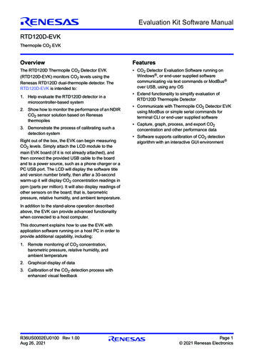
RTD120D-EVK Evaluation Kit Software Manual3.Appendix A: Background InformationThe following high-level block diagram introduces the structure of this EVK, followed by a basic functionaldescription.Character LCD(16 character x 2 lines)AntennaConnectorUSB Connectorpushbutton switchesUSBDigitalRegulatorLampDriverLinear Regulatorwith soft-startISL80101DC/DC (3A)ISL801015VBLE GPIO GPIOMCURA4W1 Thermopile to PC bridge Format conversion Basic UI System controlI2C Communications Integrated Data Flash(for calibration parameter, ABarometricPressureSensorVccINTCO2 Detector BoardA/D ConverterEOCA/DA/D A/DTHERMISTORLampSampleChamberDual ThermopileRH5Z1222D20GZO#ADOCO2REFDual th reference to the diagram, gas enters from the openings in the sample chamber and the infrared lightsource – in our case a lamp driven by a lamp driver circuit (a linear regulator with soft-start feature) emits infraredlight intermittently to penetrate the gas being measured. The dual-channel thermopile sensor is used tosimultaneously measure the infrared light intensity of both the sensitive wavelength of CO2, and of the referencewavelength. The reference light is not affected by CO2.R36US0002EU0100 Rev 1.00Aug 26, 2021Page 13
RTD120D-EVK Evaluation Kit Software Manual4.Appendix B: Terminal Mode CommandsThe following table provides a list of supported commands available in terminal mode.Table 2. Terminal CommandsCommandParametersDescription / Example?Show brief help textoTurn lamp ON(overridden by automatic ON/OFF)fTurn lamp OFF(overridden by automatic ON/OFF)start ppmStart streaming CO2 concentrationreports, in parts per million (PPM), onceper cyclestop ppmStop streaming CO2 concentrationreportsset param value set a parameter to a valuesets1 raw value Set calibration raw #1 point“set s1 raw 1234.56”sets2 raw value sets3 raw value sets4 raw value sets1 ppm value Set calibration ppm #1 pointsets2 ppm value sets3 ppm value sets4 ppm value setserial number value Set serial number 123setfilter value Set second stage filter(default to 8)setfilter adc value Set first stage(A/D) filter(default to 12) config1Report configuration settings (group 1): SerialNumber SwRev s3 raw interp droop factor digital filter digital filter adcR36US0002EU0100 Rev 1.00Aug 26, 2021Page 14
RTD120D-EVK Evaluation Kit Software ManualTable 2. Terminal Commands (Cont.)Command config2ParametersDescription / ExampleReport configuration settings (group 2): s1 ppm s2 ppm s3 ppm s4 ppm s1 raw s2 raw s3 raw s4 raw cal slope vars1Report variables (group 1): THERM adc CO2 delta adc REF delta adc raw unfiltered raw filtered BP adc HS3001 RH adc HS3001 dC adc vars2Report variables (group 2): CO2 ppm dC BP mbar HS3001 RH percent HS3001 dC THERM R THERM dC UNUSED volts snGet serial number sw revGet software revision s1 ppmGet calibration ppm #1 point s2 ppm s3 ppm s4 ppm s1 rawGet calibration raw #1 point s2 raw s3 raw s4 raw thermistorGet thermistor temperature (degrees C) ppmGet CO2 concentration, in PPM. bpGet barometric pressure reading(millibars) rhGet relative humidity reading (%) amb tGet ambient temperature (degrees C)R36US0002EU0100 Rev 1.00Aug 26, 2021Page 15
RTD120D-EVK Evaluation Kit Software ManualTable 2. Terminal Commands (Cont.)CommandParametersDescription / Example raw ufGet un-filtered RAW value rawGet filtered RAW value co2 onGet CO2 thermopile readingwith lamp ON co2 offGet CO2 thermopile readingwith lamp OFF ref onGet reference thermopile readingwith lamp ON ref offGet reference thermopile readingwith lamp OFF!65Set Defaults!66Load Defaults!67Turn lamp ON!68Turn lamp OFF!69Set calibration raw #1 point!70Set calibration raw #2 point!71(unused)!72(unused)!73filter 2!74filter 4!75filter 8!76filter 12!77filter 20!78filter 30!79filter 40!80clear warm-up flag!81compute slope!82filter 1!83Set calibration raw #3 point!84flash read!85flash write!86flash init!87filter adc 1!88filter adc 2!89filter adc 4!90filter adc 8!91filter adc 12!92filter adc 16R36US0002EU0100 Rev 1.00Aug 26, 2021Page 16
RTD120D-EVK Evaluation Kit Software ManualTable 2. Terminal Commands (Cont.)CommandParametersDescription / Example!93(unused)!94compute droop!95(unused)!96Set calibration raw #4 pointsave to flashSave parameters to flash memory5.Revision HistoryRevisionDate1.00Aug 26, 2021DescriptionInitial release.R36US0002EU0100 Rev 1.
Aug 26, 2021