Transcription
Reference ManualOriginal InstructionsMicroLogix Controllers to Micro800 Controllers Migration GuideCatalog Numbers Bulletin 1761, Bulletin 1762, Bulletin 1763, and Bulletin 2080
Important User InformationRead this document and the documents listed in the additional resources section about installation, configuration, andoperation of this equipment before you install, configure, operate, or maintain this product. Users are required tofamiliarize themselves with installation and wiring instructions in addition to requirements of all applicable codes, laws,and standards.Activities including installation, adjustments, putting into service, use, assembly, disassembly, and maintenance arerequired to be carried out by suitably trained personnel in accordance with applicable code of practice.If this equipment is used in a manner not specified by the manufacturer, the protection provided by the equipment maybe impaired.In no event will Rockwell Automation, Inc. be responsible or liable for indirect or consequential damages resulting fromthe use or application of this equipment.The examples and diagrams in this manual are included solely for illustrative purposes. Because of the many variables andrequirements associated with any particular installation, Rockwell Automation, Inc. cannot assume responsibility orliability for actual use based on the examples and diagrams.No patent liability is assumed by Rockwell Automation, Inc. with respect to use of information, circuits, equipment, orsoftware described in this manual.Reproduction of the contents of this manual, in whole or in part, without written permission of Rockwell Automation,Inc., is prohibited.Throughout this manual, when necessary, we use notes to make you aware of safety considerations.WARNING: Identifies information about practices or circumstances that can cause an explosion in a hazardousenvironment, which may lead to personal injury or death, property damage, or economic loss.ATTENTION: Identifies information about practices or circumstances that can lead to personal injury or death, propertydamage, or economic loss. Attentions help you identify a hazard, avoid a hazard, and recognize the consequence.IMPORTANTIdentifies information that is critical for successful application and understanding of the product.Labels may also be on or inside the equipment to provide specific precautions.SHOCK HAZARD: Labels may be on or inside the equipment, for example, a drive or motor, to alert people that dangerousvoltage may be present.BURN HAZARD: Labels may be on or inside the equipment, for example, a drive or motor, to alert people that surfaces mayreach dangerous temperatures.ARC FLASH HAZARD: Labels may be on or inside the equipment, for example, a motor control center, to alert people topotential Arc Flash. Arc Flash will cause severe injury or death. Wear proper Personal Protective Equipment (PPE). Follow ALLRegulatory requirements for safe work practices and for Personal Protective Equipment (PPE).
Table of ContentsAbout This Publication. . . . . . . . . . . . . . . . . . . . . . . . . . . . . . . . . . . . . . . . .Audience . . . . . . . . . . . . . . . . . . . . . . . . . . . . . . . . . . . . . . . . . . . . . . . . . . . . . .Required Software. . . . . . . . . . . . . . . . . . . . . . . . . . . . . . . . . . . . . . . . . . . . . .Summary of Changes . . . . . . . . . . . . . . . . . . . . . . . . . . . . . . . . . . . . . . . . . . .Additional Resources . . . . . . . . . . . . . . . . . . . . . . . . . . . . . . . . . . . . . . . . . . .55566Chapter 1Micro800 Controller OverviewController Dimensions . . . . . . . . . . . . . . . . . . . . . . . . . . . . . . . . . . . . . . . . 10Feature and Specification Comparison . . . . . . . . . . . . . . . . . . . . . . . . . . 17Chapter 2Plan Hardware Migration with Generate Hardware Configuration . . . . . . . . . . . . . . . . . . . . . . . . . . . . . 21Integrated Architecture BuilderChapter 3Migration ConsiderationsMigrate From a MicroLogix 1000 Controller . . . . . . . . . . . . . . . . . . . .Migrate From a MicroLogix 1100 Controller . . . . . . . . . . . . . . . . . . . .Migrate From a MicroLogix 1200 Controller . . . . . . . . . . . . . . . . . . . .Wiring Configuration . . . . . . . . . . . . . . . . . . . . . . . . . . . . . . . . . . . . . . . . .25272930Chapter 4Convert a MicroLogix Project to Overview . . . . . . . . . . . . . . . . . . . . . . . . . . . . . . . . . . . . . . . . . . . . . . . . . . . . . 59Before You Begin. . . . . . . . . . . . . . . . . . . . . . . . . . . . . . . . . . . . . . . . . . . . . . 59a Micro800 ProjectWhat You Need . . . . . . . . . . . . . . . . . . . . . . . . . . . . . . . . . . . . . . . . . . . . . .Convert Your Project with the Converter Tool . . . . . . . . . . . . . . . . . .Convert Your Project Manually . . . . . . . . . . . . . . . . . . . . . . . . . . . . . . . .Generate an Existing RSLogix 500/RSLogix Micro Project ReportCreate Equivalent Program Files. . . . . . . . . . . . . . . . . . . . . . . . . . . . . . . .Create Representative Data Files . . . . . . . . . . . . . . . . . . . . . . . . . . . . . . .Create Equivalent Logic in Program File . . . . . . . . . . . . . . . . . . . . . . . .Logix Examples . . . . . . . . . . . . . . . . . . . . . . . . . . . . . . . . . . . . . . . . . . . . . . .Build and Test Your Project. . . . . . . . . . . . . . . . . . . . . . . . . . . . . . . . . . . .656579798081838491Chapter 5RLL Instruction MappingOverview . . . . . . . . . . . . . . . . . . . . . . . . . . . . . . . . . . . . . . . . . . . . . . . . . . . . . 99Definitions, Acronyms, and Abbreviations . . . . . . . . . . . . . . . . . . . . . . 99Bit Shift . . . . . . . . . . . . . . . . . . . . . . . . . . . . . . . . . . . . . . . . . . . . . . . . . . . . . 100Communication . . . . . . . . . . . . . . . . . . . . . . . . . . . . . . . . . . . . . . . . . . . . . 105Comparison . . . . . . . . . . . . . . . . . . . . . . . . . . . . . . . . . . . . . . . . . . . . . . . . . 106Control . . . . . . . . . . . . . . . . . . . . . . . . . . . . . . . . . . . . . . . . . . . . . . . . . . . . . 118I/O Related Interrupt . . . . . . . . . . . . . . . . . . . . . . . . . . . . . . . . . . . . . . . . 123Selectable Timed Interrupts . . . . . . . . . . . . . . . . . . . . . . . . . . . . . . . . . . . 127File Manipulation . . . . . . . . . . . . . . . . . . . . . . . . . . . . . . . . . . . . . . . . . . . . 131Math . . . . . . . . . . . . . . . . . . . . . . . . . . . . . . . . . . . . . . . . . . . . . . . . . . . . . . . . 133Move and Logical . . . . . . . . . . . . . . . . . . . . . . . . . . . . . . . . . . . . . . . . . . . . 146Rockwell Automation Publication 2080-RM002B-EN-E - June 20193
Table of ContentsRelay Type . . . . . . . . . . . . . . . . . . . . . . . . . . . . . . . . . . . . . . . . . . . . . . . . . . 155Timer and Counter . . . . . . . . . . . . . . . . . . . . . . . . . . . . . . . . . . . . . . . . . . 162Miscellaneous . . . . . . . . . . . . . . . . . . . . . . . . . . . . . . . . . . . . . . . . . . . . . . . . 176Appendix AAdditional ExamplesConfigure Interrupts on a Micro800 Controller . . . . . . . . . . . . . . . . 179Set Up High-Speed Counter (HSC) Instruction Variables. . . . . . . 181Appendix BOriginal and Converted Pickand-Place Ladder Diagrams4Original RSLogix 500/RSLogix Micro Ladder Diagram . . . . . . . . . 183Connected Components Workbench Ladder Diagram (Converter Tool). . . . . . . . . . . . . . . . . . . . . . . . . . . . . . . . . . . . . . . . . . . . . . . . . . . . . . . . . . . . . 185Connected Components Workbench Ladder Diagram(Manual Conversion). . . . . . . . . . . . . . . . . . . . . . . . . . . . . . . . . . . . . . . . . 190Rockwell Automation Publication 2080-RM002B-EN-E - June 2019
PrefaceAbout This PublicationThis document serves as a guide for replacing your existing MicroLogix 1000,MicroLogix 1100, or MicroLogix 1200 controller with a Micro800 family ofcontrollers.The Micro800 family of controllers includes the Micro810 , Micro820 ,Micro830 , Micro850 , and Micro870 controllers.Descriptions, wiring diagrams, dimensions, features, and specifications of thecontrollers are provided to help you select the appropriate Micro800 controller toreplace your MicroLogix controller.This document shows you how to use the software tools to select a suitableMicro800 controller, and also how to convert your MicroLogix programs to workwith the Micro800 controller.AudienceThe intended audience of this document is owners of MicroLogix 1000,MicroLogix 1100, and MicroLogix 1200 controllers who are migrating to theMicro800 family of controllers, and who are familiar with the RSLogix 500 /RSLogix Micro programming software. Knowledge of programming in ladderlanguage is expected to be able to program Micro800 systems effectively.Required SoftwareTo complete the steps in this document, Connected Components Workbench software version 12 or later is required. As the main programming software forMicro800 systems. Connected Components Workbench software provides achoice of IEC 61131-3 programming languages (ladder diagram, function blockdiagram, structured text) with user-defined function block support thatoptimizes machine control.You need Connected Components Workbench software to write your ladderdiagram, function block diagram, or structured text programs, to execute theprograms, and to see the results.This document uses two features that are available in Connected ComponentsWorkbench software version 12 or later. MicroLogix to Micro800 Converter toolThe MicroLogix to Micro800 Converter tool converts an RSLogix 500/RSLogix Micro project into a Connected Components Workbenchproject. It provides conversion for ladder diagram (LD) programminglanguages in the MicroLogix processor.Rockwell Automation Publication 2080-RM002B-EN-E - June 20195
PrefaceThe onverter tool can convert most RSLogix 500/RSLogix Microinstruction blocks. However, you may need to modify the convertedfunction blocks to confirm that they work properly. All information thatrequires additional modifications are logged in a conversion report, andthis document shows you how to make the changes. Micro800 SimulatorThe Micro800 Simulator can be used to perform testing andtroubleshooting of a Connected Components Workbench project,without a physical Micro800 controller.Summary of ChangesTopicPageUpdated Preface.5Combined dimensions for various Micro830 controllers. Added dimensions for MicroLogix 1100,MicroLogix 1200, Micro 850, and Micro870 controllers.11, 12,14, 15, 16Updated feature and specification comparison table for MicroLogix 1000 controllers. Added tablesfor MicroLogix 1100 and MicroLogix 1200 controllers.17, 18, 19Added chapter “Plan Hardware Migration with Integrated Architecture Builder”.21Renamed chapter “Select a Suitable Micro800 Controller” to “Migration Considerations”. Addedinformation for migrating from a MicroLogix 1100 or MicroLogix 1200 controller.25, 27, 29Added wiring diagrams for MicroLogix 1100, MicroLogix 1200, Micro850, and Micro870 controllers. 39, 42, 54, 56Additional Resources6Renamed chapter “Convert an RSLogix 500 Project to a Connected Components Project” to“Convert a MicroLogix Project to a Micro800 Project”. Revised chapter with new information on theconversion process and the use of the MicroLogix to Micro800 Converter tool and Micro800Simulator.59, 65, 79, 84, 91Updated High-Speed Counter instruction description with information of new HSC instruction setin Connected Components Workbench software.173Moved some examples from chapter “Convert a MicroLogix Project to a Micro800 Project” into anew appendix.179These documents contain additional information concerning related productsfrom Rockwell Automation.ResourceDescriptionMicro800 Programmable Controllers General Instructions,publication 2080-RM001Provides reference information about the instruction setavailable for developing programs for use in Micro800control systems.Micro820 Programmable Controllers User Manual,publication 2080-UM005A more detailed description of how to install and use yourMicro820 programmable controllers.Micro830, Micro850, and Micro870 ProgrammableControllers User Manual, publication 2080-UM002A more detailed description of how to install and use yourMicro830, Micro850, and Micro870 programmablecontrollers.Micro800 Expansion Modules User Manual,publication 2080-UM003Description of features, installation, wiring, andspecifications for the Micro800 expansion modules.Micro800 Plug-in Modules User Manual,publication 2080-UM004Description of features, installation, wiring, andspecifications for the Micro800 plug-in modules.Rockwell Automation Publication 2080-RM002B-EN-E - June 2019
PrefaceResourceDescriptionGetting Started with Motion Control Using a SimulatedAxis Quick Start, publication 2080-QS001Provides instructions to implement a motion controlproject using Connected Components Workbenchsoftware.Micro800 Controllers: Getting Started with CIP ClientMessaging Quick Start, publication 2080-QS002Provides instructions on how to use CIP Generic andCIP Symbolic messaging with Micro800 controllers.Micro800 Programmable Controllers: Getting Started withPanelView Plus Quick Start, publication 2080-QS003Provides instructions on how to use global variables withMicro800 controllers together with PanelView PlusHMI terminals.Setup Micro800 Controllers on FactoryTalk Gateway QuickStart, publication 2080-QS005Provides instructions on how to configure a Micro800controller on FactoryTalk Gateway.Industrial Automation Wiring and Grounding Guidelines,publication 1770-4.1Provides general guidelines for installing a RockwellAutomation industrial system.Product Certifications website, ation/overview.pageProvides declarations of conformity, certificates, and othercertification details.You can view or download publications ture-library/overview.page.To order paper copies of technical documentation, contact your localAllen-Bradley distributor or Rockwell Automation sales representative.Rockwell Automation Publication 2080-RM002B-EN-E - June 20197
PrefaceNotes:8Rockwell Automation Publication 2080-RM002B-EN-E - June 2019
Chapter1Micro800 Controller OverviewMicro800 controllers are designed for low-cost, standalone machines. Theseeconomical small-size programmable logic controllers (PLCs) are available indifferent form factors based on the number of I/O points that are embedded inthe base, with a range of features that are intended to address differentrequirements. The Micro800 family shares programming environment,accessories, and plug-ins that allow machine builders to personalize the controllerfor specific capabilities.Micro810 controllers function as a smart relay with high current relay outputs,but with the programming capabilities of a micro PLC. The Micro810controllers come in a 12-point form factor.Micro820 controllers are designed for smaller standalone machines and remoteautomation projects. They have embedded Ethernet and serial ports and amicroSD slot for data logging and recipe management. These controllers comeas 20-point form factors that can accommodate up to two plug-in modules. Theyalso support the Micro800 Remote LCD (2080-REMLCD) module for easierconfiguration of settings such as IP address. The Remote LCD module can alsofunction as a simple IP65 text display.Micro830 controllers are designed for standalone machine control applications.They have flexible communications and I/O capabilities with up to five plug-ins.They come in 10-, 16-, 24-, or 48-point form factors.Micro850 expandable controllers are designed for applications that require moredigital and analog I/O or higher performance analog I/O. They can support upto four expansion I/O. Micro850 controllers include additional communicationconnection options through an embedded 10/100 Base-T Ethernet port.Micro870 controllers offer machine builders and end users a higher level ofscalability, flexibility, and customization. Designed for large standalone machineapplications, the Micro870 controller comes with great memory capacity toenable more modular program and use of user-defined function blocks. They cansupport up to eight expansion I/O.Several Micro830, Micro850, and Micro870 controllers support basicpositioning through embedded pulse train outputs (PTO). These controllers alsoallow you to configure up to six high-speed counters (HSC), and choose fromnine HSC operation modes. HSC is supported on all Micro830, Micro850, andMicro870 controller catalogs, except on 2080-LCxx-xxAWB. PTO is onlysupported on Micro830, Micro850, and Micro870 controller catalog numbersthat end in BB or VB.Rockwell Automation Publication 2080-RM002B-EN-E - June 20199
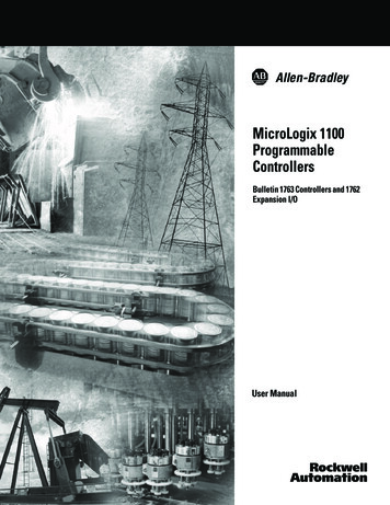
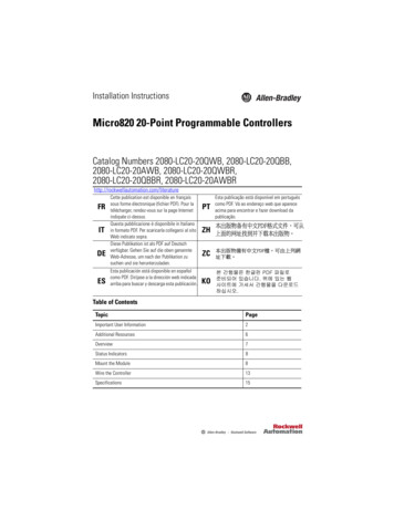
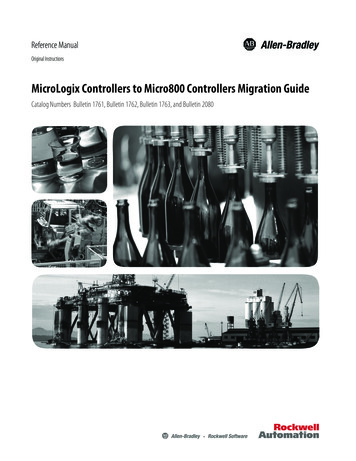
Chapter 1Micro800 Controller OverviewThe following tables describe the dimensions for the MicroLogix controllers andthe Micro800 controllers.Controller DimensionsMicroLogix 1000 Controller DimensionsCCABCatalog NumberABC1761-L10BWA120 mm (4.72 in.)73 mm (2.87 in.)80 mm (3.15 in.)1761-L16AWA133 mm (5.24 in.)1761-L16BWA120 mm (4.72 in.)1761-L16NWA1761-L20AWA-5A200 mm (7.87 A1761-L10BWB120 mm (4.72 in.)40 mm (1.57 61-L20BWB-5A200 mm (7.87 in.)1761-L32BBB1761-L32BWB10Rockwell Automation Publication 2080-RM002B-EN-E - June 2019
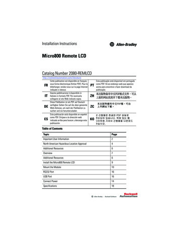
Micro800 Controller OverviewChapter 1MicroLogix 1100 Controller DimensionsCESCCOKBACatalog NumberABC1763-L16AWA110 mm (4.33 in.)87 mm (3.43 in.)90 mm (3.54 in.)1763-L16BWA1763-L16BBB1763-L16DWDRockwell Automation Publication 2080-RM002B-EN-E - June 201911
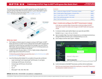
Chapter 1Micro800 Controller OverviewMicroLogix 1200 Controller DimensionsCC01COMBACatalog NumberABC1762-L24AWA110 mm (4.33 in.)87 mm (3.43 in.)90 mm (3.54 1762-L24BXBR1762-L40AWA160 mm (6.30 1762-L40BXBR12Rockwell Automation Publication 2080-RM002B-EN-E - June 2019
Micro800 Controller OverviewChapter 1Micro820 Controller DimensionsABCCatalog NumberABC2080-LC20-20AWB104 mm (4.09 in.)75 mm (2.95 in.)90 mm (3.54 R2080-LC20-20QBB2080-LC20-20QBBRRockwell Automation Publication 2080-RM002B-EN-E - June 201913
Chapter 1Micro800 Controller OverviewMicro830 Controller DimensionsAABCCBACCatalog NumberABC2080-LC30-10QWB100 mm (3.94 in.)80 mm (3.15 in.)90 mm (3.54 080-LC30-16QVB2080-LC30-24QWB150 mm (5.91 10 mm (8.27 4Rockwell Automation Publication 2080-RM002B-EN-E - June 2019B
Micro800 Controller OverviewChapter 1Micro850 Controller DimensionsABCBACCatalog NumberABC2080-LC50-24AWB158 mm (6.22 in.)80 mm (3.15 in.)90 mm (3.54 080-LC50-48AWB283 mm (9.37 ockwell Automation Publication 2080-RM002B-EN-E - June 201915
Chapter 1Micro800 Controller OverviewMicro870 Controller DimensionsABCBACCatalog NumberABC2080-LC70-24AWB157 mm (6.22 in.)80 mm (3.15 in.)90 mm (3.54 2080-LC70-24QBBK16Rockwell Automation Publication 2080-RM002B-EN-E - June 2019
Micro800 Controller OverviewFeature and SpecificationComparisonChapter 1The following tables describe the differences in features and specificationsbetween MicroLogix controllers and Micro800 controllers. For more details onthe specifications, see the respective controller user manual.MicroLogix 1000 Controllers and Micro800 Controllers ComparisonFeaturesMicroLogix 1000 ControllerMicro820 ControllerMicro830 ControllerMemory (in user words)User program/User data1 KB combined (preconfigured)10/20 KB4/8 KB – 10/16-point controllers10/20 KB – 24/48-point controllersMemory module(for program backup and transport)Handheld programmerMicroSD card(1)Plug-in module – 2080-MEMBAK-RTC or2080-MEMBAK-RTC2Online editing/Run Mode ChangeNoneYes(2)Embedded digital I/O, max211948Embedded analog I/OTwo current and two voltage inputs withone current or voltage output on 20 pointcontrollersOne 0 10V analog output,four 24V DC digital inputs that can beconfigured as 0 10V analog inputs (DCinput controllers only), andplug-in module – 2080-IF2, 2080-IF4Plug-in module – 2080-IF2, 2080-IF4Expansion I/O supportedNoneThermocouple/RTDNonePlug-in module – 2080-RTD2, 2080-TC2Network expansion I/ONonePlug-in module – 2080-DNET20 (up to 20 nodes for I/O operation)Trim potentiometerNonePlug-in module – 2080-TRIMPOT6PIDNoneYes (limited only by memory and I/O)High-speed counters (embedded)1 @ 6.6 kHz(not supported on AC input controllers)Plug-in module – 2080-MOT-HSC2 @100 kHz – 10/16-point controllers4 @100 kHz – 24-point controllers6 @100 kHz – 48-point controllers(not supported on AC input controllers)Motion: PTO/PWM supportNonePWM only1 @ 5.5 kHz(not supported on relay outputcontrollers)1 @ 100 kHz – 10/16-point controllers2 @ 100 kHz – 24-point controllers3 @ 100 kHz – 48-point controllers(not supported on relay outputcontrollers)Real-time clockNoneEmbeddedPlug-in module – 2080-MEMBAK-RTC,2080-MEMBAK-RTC2Recipe storageNoneMicroSD card(1)Plug-in module – 2080-SDMEMRTC-SCand microSD card(1)Data loggingNoneMicroSD card(1)Plug-in module – 2080-SDMEMRTC-SCand microSD card(1)Floating point mathNone32-bit and 64-bit120/240V ACYesPower supply module – 2080-PSAC-12WPower supply module –2080-PS120-240VAC24V DCYesEmbedded RS-232/RS-485 serial portcombo8-pin min DIN RS-232/RS-485 serial portcomboMemoryInputs / OutputsAdded FunctionalityOperating PowerCommunicationRS-232 port8-pin mini DINRockwell Automation Publication 2080-RM002B-EN-E - June 201917
Chapter 1Micro800 Controller OverviewFeaturesMicroLogix 1000 ControllerMicro820 ControllerMicro830 ControllerDeviceNet Peer-to-Peer Messaging,Slave I/ONonePlug-in module – 2080-DNET20 (up to 20 nodes for I/O operation)EtherNet/IPWith 1761-NET-ENI or 1761-NET-ENIWYesDH-485With 1761-NET-AICNoneSCADA RTU – DF1 Half-duplex SlaveYesNoneSCADA RTU – DF1 Radio ModemNoneSCADA RTU – Modbus RTU SlaveNoneYesSCADA RTU – Modbus RTU MasterNoneYesModbus TCPNoneYesASCII – Read/WriteNoneYesCIP SerialNoneYesNoneNone(1) We recommend using the Allen-Bradley 2080-SD-2GB microSD card. The 2080-SDMEMRTC-SC plug-in module is an Encompass partner product.(2) Requires Connected Components Workbench Developer Edition software version 12 or later, and Micro800 controller firmware revision 12 or later.MicroLogix 1100 Controllers and Micro800 Controllers ComparisonFeaturesMicroLogix 1100 ControllerMicro820 ControllerMicro850 ControllerMemory (in user words)User program/User data4 KB user program with 4 KB user data120 KB user program with 20 KB user data(1)Memory module(for program backup and transport)1763-MM1 memory moduleMicroSD card(2)Online editing/Run Mode ChangeYesYes(3)Embedded digital I/O, max161948Embedded analog I/OTwo 0 10V analog inputsOne 0 10V analog output,four 24V DC digital inputs that can beconfigured as 0 10V analog inputs (DCinput controllers only), andplug-in module – 2080-IF2, 2080-IF4Plug-in module – 2080-IF2, 2080-IF4Expansion modules supportedUp to four expansion modulesNoneUp to four expansion modulesThermocouple/RTDExpansion module – 1762-IT4, 1762-IR4NoneExpansion module – 2085-IRT4Network expansion I/ONonePlug-in module – 2080-DNET20 (up to 20 nodes for I/O operation)Trim potentiometerLCD and keypadPlug-in module – 2080-TRIMPOT6PIDYes (limited only by memory and I/O)High-speed counters (embedded)1 @ 40 kHzPlug-in module – 2080-MOT-HSC4 @ 100 kHz – 24-point controllers6 @ 100 kHz – 48-point controllers(not supported on AC input controllers)Motion: PTO/PWM support1763-L16BBB only2 @ 40 kHzPWM only1 @ 5.5 kHz(not supported on relay outputcontrollers)PTO only2 @ 100 kHz – 24-point controllers3 @ 100 kHz – 48-point controllers(not supported on relay outputcontrollers)Real-time clockEmbeddedEmbeddedPlug-in module – 2080-MEMBAK-RTC,2080-MEMBAK-RTC2MemoryPlug-in module – 2080-MEMBAK-RTC,2080-MEMBAK-RTC2Inputs / OutputsAdded Functionality18Rockwell Automation Publication 2080-RM002B-EN-E - June 2019
Micro800 Controller OverviewFeaturesMicroLogix 1100 ControllerMicro820 Controller(2)Chapter 1Micro850 ControllerRecipe storageYesMicroSD cardPlug-in module – 2080-SDMEMRTC-SCand microSD card(2)Data loggingYesMicroSD card(2)Plug-in module – 2080-SDMEMRTC-SCand microSD card(2)Floating point math32-bit32-bit and 64-bit120/240V ACYesPower supply module – 2080-PSAC-12W24V DCYes12V DCYesNoneRS-232/485 port8-pin mini DIN (isolated)Plug-in module – 2080-SERIALISOL(isolated) or6-pin terminal block (non-isolated)DeviceNet Peer-to-Peer Messaging,Slave I/ONonePlug-in module – 2080-DNET20 (up to 20 nodes for I/O operation)EtherNet/IPYesOperating PowerPower supply module A RTU – DF1 Half-duplex SlaveYesNoneSCADA RTU – DF1 Radio ModemYesNoneSCADA RTU – Modbus RTU SlaveYesSCADA RTU – Modbus RTU MasterYesModbus TCPNoneASCII – Read/WriteYesCIP SerialNonePlug-in module – 2080-SERIALISOL(isolated) or8-pin min DIN (non-isolated)YesYes(1) For a similar program, a Micro800 program appears to be about five times larger than a MicroLogix program. However Micro820, Micro850, and Micro870 controllers have over 160 KB of memory.Based on an allocation of 120 KB for user programs, their effective memory is about four times larger than a MicroLogix controller.(2) We recommend using the Allen-Bradley 2080-SD-2GB microSD card. The 2080-SDMEMRTC-SC plug-in module is an Encompass partner product.(3) Requires Connected Components Workbench Developer Edition software version 12 or later, and Micro800 controller firmware revision 12 or later.MicroLogix 1200 Controllers and Micro800 Controllers ComparisonFeaturesMicroLogix 1200 ControllerMicro850 ControllerMicro870 ControllerMemory (in user words)User program/User data6 KB (3 KB user program with 3 KBuser data120 KB user program with 20 KBuser data(1)240 KB user program with 40 KBuser data(1)Memory module(for program backup and transport)Yes, 1762-MM1 or 1762-MM1RTCPlug-in module – 2080-MEMBAK-RTC, 2080-MEMBAK-RTC2Run Mode ChangeNoneYes(2)Embedded digital I/O, max404824Embedded analog I/ONoneExpansion modules supportedUp to six expansion modulesUp to four expansion modulesUp to eight expansion modulesThermocouple/RTDExpansion module – 1762-IT4, 1762-IR4Expansion module – 2085-IRT4MemoryInputs / OutputsRockwell Automation Publication 2080-RM002B-EN-E - June 201919
Chapter 1Micro800 Controller OverviewFeaturesMicroLogix 1200 ControllerMicro850 ControllerMicro870 ControllerNetwork expansion I/ONonePlug-in module – 2080-DNET20 (up to 20 nodes for I/O operation)Trim potentiometerTwo built-in digital trim potentiometersPlug-in module – 2080-TRIMPOT6PIDYes (limited only by memory and I/O)High-speed counters (embedded)Up to four high-speed DC inputs4 @ 100 kHz – 24-point controllers6 @ 100 kHz – 48-point controllers(not supported on AC input controllers)4 @ 100 kHz(not supported on AC input controllers)Motion: PTO/PWM support1 @ 20 kHz(supported by 1762-LxxBXB and1762-LxxBXBR controllers only)PTO only2 @ 100 kHz – 24-point controllers3 @ 100 kHz – 48-point controllers(not supported on relay outputcontrollers)PTO only2 @ 100 kHz(not supported on relay outputcontrollers)Real-time clockYes, 1762-RTC or 1762-MM1RTCPlug-in module – 2080-MEMBAK-RTC,2080-MEMBAK-RTC2Plug-in module – 2080-MEMBAK-RTC2Recipe storageNonePlug-in module – 2080-SDMEMRTC-SC and microSD card(3)Data loggingNonePlug-in module – 2080-SDMEMRTC-SC and microSD card(3)Floating point math32-bit32-bit and 64-bit120/240V ACYesPower supply module – 2080-PS120-240VAC24V DCYesAdded FunctionalityOperating PowerCommunicationRS-232/485 port8-pin mini DIN (isolated)Plug-in module –2080-SERIALISOL (isolated) or 8-pin mini DIN (non-isolated)DeviceNet Peer-to-Peer Messaging,Slave I/ONonePlug-in module – 2080-DNET20 (up to 20 nodes for I/O operation)EtherNet/IPNoneYesDH-485YesNoneSCADA RTU – DF1 Half-duplex SlaveYesNoneSCADA RTU – DF1 Radio ModemYesNoneSCADA RTU – Modbus RTU SlaveYesSCADA RTU – Modbus RTU MasterYesModbus TCPNoneASCII – Read/WriteYesCIP SerialNoneYesYes(1) For a similar program, a Micro800 program appears to be about five times larger than a MicroLogix program. However Micro820, Micro850, and Micro870 controllers have over 160 KB of memory.Based on an allocation of 120 KB for user programs, their effective memory is about four times larger than a MicroLogix controller.(2) Requires Connected Components Workbench Developer Edition software version 12 or later, and Micro800 controller firmware revision 12 or later.(3) We recommend using the Allen-Bradley 2080-SD-2GB microSD card. The 2080-SDMEMRTC-SC plug-in module is an Encompass partner product.20Rockwell Automation Publication 2080-RM002B-EN-E - June 2019
Chapter2Plan Hardware Migration with IntegratedArchitecture BuilderThis chapter describes how to use the MicroLogix Migration Wizard withinIntegrated Architecture Builder (IAB) software to assist with converting yourMicroLogix controller to a compatible controller. At the base level,MicroLogix 1000, MicroLogix 1100, and MicroLogix 1200 controllers migrateto Micro800 controllers. MicroLogix 1500 controllers migrate toMicroLogix 1400 controllers or CompactLogix (L1/L2) controllers.Generate HardwareConfigurationTo convert your MicroLogix system to a compatible controller system, do thefollowing:1. Launch Integrated Architecture Builder software from Start - Programs- Rockwell Automation - Integrated Architecture Builder - IntegratedArchitecture Builder.Alternatively, you can double-click the IAB icon on your computer.2. Under Create, click New Project.Rockwel
The onverter tool can convert most RSLogix 500/RSLogix Micro instruction blocks. However, you may need to modify the converted function blocks to confirm that they work properly. All information that requires additional modifications are logged in a conversion report, and this document shows you how to make the changes. Micro800 Simulator