Transcription
MicroLogix 1100ProgrammableControllersBulletin 1763 Controllers and 1762Expansion I/OUser Manual
Important User InformationSolid state equipment has operational characteristics differing from those ofelectromechanical equipment. Safety Guidelines for the Application,Installation and Maintenance of Solid State Controls (publication SGI-1.1available from your local Rockwell Automation sales office or online athttp://literature.rockwellautomation.com) describes some importantdifferences between solid state equipment and hard-wired electromechanicaldevices. Because of this difference, and also because of the wide variety ofuses for solid state equipment, all persons responsible for applying thisequipment must satisfy themselves that each intended application of thisequipment is acceptable.In no event will Rockwell Automation, Inc. be responsible or liable forindirect or consequential damages resulting from the use or application ofthis equipment.The examples and diagrams in this manual are included solely for illustrativepurposes. Because of the many variables and requirements associated withany particular installation, Rockwell Automation, Inc. cannot assumeresponsibility or liability for actual use based on the examples and diagrams.No patent liability is assumed by Rockwell Automation, Inc. with respect touse of information, circuits, equipment, or software described in this manual.Reproduction of the contents of this manual, in whole or in part, withoutwritten permission of Rockwell Automation, Inc., is prohibited.Throughout this manual, when necessary, we use notes to make you awareof safety considerations.WARNINGIMPORTANTATTENTIONIdentifies information about practices or circumstances that can causean explosion in a hazardous environment, which may lead to personalinjury or death, property damage, or economic loss.Identifies information that is critical for successful application andunderstanding of the product.Identifies information about practices or circumstances that can leadto: personal injury or death, property damage, or economic loss.Attentions help you identify a hazard, avoid a hazard, and recognizethe consequence.SHOCK HAZARDLabels may be on or inside the equipment, such as a drive or motor, toalert people that dangerous voltage may be present.BURN HAZARDLabels may be on or inside the equipment, such as a drive or motor, toalert people that surfaces may reach dangerous temperatures.Rockwell Automation, DeviceNet, ModBus, Allen-Bradley, SLC 5/02, SLC 5/03, PLC-5, MicroLogix, SLC 500, RSLogix, RSLinx, andRSLogix 500 are trademarks of Rockwell Automation, Inc.Trademarks not belonging to Rockwell Automation are property of their respective companies.
Table of ContentsPrefaceWho Should Use this Manual. . . . . . . . . . .Purpose of this Manual . . . . . . . . . . . . . . .Related Documentation . . . . . . . . . . . .Common Techniques Used in this Manual . 9. 91010Hardware Features . . . . . . . . . . . . . . . . . . . . . . . . . . . . . . .Component Descriptions . . . . . . . . . . . . . . . . . . . . . . . . . . .MicroLogix 1100 Memory Module and Built-in Real-TimeClock . . . . . . . . . . . . . . . . . . . . . . . . . . . . . . . . . . . . . .1762 Expansion I/O . . . . . . . . . . . . . . . . . . . . . . . . . . . .Communication Cables . . . . . . . . . . . . . . . . . . . . . . . . . . . .Programming . . . . . . . . . . . . . . . . . . . . . . . . . . . . . . . . . . .Firmware Revision History . . . . . . . . . . . . . . . . . . . . . . .Communication Options . . . . . . . . . . . . . . . . . . . . . . . . . . .1112Chapter 1Hardware Overview121314141516Chapter 2Installing Your Controller3Agency Certifications. . . . . . . . . . . . . . . . . . . . . .Compliance to European Union Directives . . . . . .EMC Directive . . . . . . . . . . . . . . . . . . . . . . . .Low Voltage Directive . . . . . . . . . . . . . . . . . .Installation Considerations. . . . . . . . . . . . . . . . . .Safety Considerations . . . . . . . . . . . . . . . . . . . . .Hazardous Location Considerations . . . . . . . .Disconnecting Main Power. . . . . . . . . . . . . . .Safety Circuits . . . . . . . . . . . . . . . . . . . . . . . .Power Distribution. . . . . . . . . . . . . . . . . . . . .Periodic Tests of Master Control Relay Circuit .Power Considerations . . . . . . . . . . . . . . . . . . . . .Isolation Transformers . . . . . . . . . . . . . . . . . .Power Supply Inrush . . . . . . . . . . . . . . . . . . .Loss of Power Source. . . . . . . . . . . . . . . . . . .Input States on Power Down . . . . . . . . . . . . .Other Types of Line Conditions . . . . . . . . . . .Preventing Excessive Heat . . . . . . . . . . . . . . . . . .Master Control Relay . . . . . . . . . . . . . . . . . . . . . .Using Emergency-Stop Switches . . . . . . . . . . .Schematic (Using IEC Symbols) . . . . . . . . . . .Schematic (Using ANSI/CSA Symbols). . . . . . .Installing a Memory Module . . . . . . . . . . . . . . . .Using the Battery . . . . . . . . . . . . . . . . . . . . . . . .Connecting the Battery Wire Connector . . . . .Controller Mounting Dimensions . . . . . . . . . . . . .Controller and Expansion I/O Spacing . . . . . . . . .Mounting the Controller . . . . . . . . . . . . . . . . . . .DIN Rail Mounting . . . . . . . . . . . . . . . . . . . . 334343536Publication 1763-UM001B-EN-P - April 2007
4Table of ContentsPanel Mounting . . . . . . . . . .1762 Expansion I/O DimensionsMounting 1762 Expansion I/O . .DIN Rail Mounting . . . . . . . .Panel Mounting . . . . . . . . . .Connecting Expansion I/O . . . .373838383940Wiring Requirements . . . . . . . . . . . . . . . . . . . . . . .Wiring Recommendation . . . . . . . . . . . . . . . . . .Wiring the Terminal Block . . . . . . . . . . . . . . . . .Using Surge Suppressors . . . . . . . . . . . . . . . . . . . . .Recommended Surge Suppressors . . . . . . . . . . .Grounding the Controller . . . . . . . . . . . . . . . . . . . .Wiring Diagrams . . . . . . . . . . . . . . . . . . . . . . . . . . .Terminal Block Layouts . . . . . . . . . . . . . . . . . . .Terminal Groupings . . . . . . . . . . . . . . . . . . . . . .Sinking and Sourcing Wiring Diagrams . . . . . . . . . .1763-L16AWA, 1763-L16BWA, 1763-L16BBB and1763-L16DWD Wiring Diagrams . . . . . . . . . . . . .Controller I/O Wiring . . . . . . . . . . . . . . . . . . . . . . .Minimizing Electrical Noise. . . . . . . . . . . . . . . . .Wiring Your Analog Channels . . . . . . . . . . . . . . . . .Analog Channel Wiring Guidelines . . . . . . . . . . .Minimizing Electrical Noise on Analog Channels .Grounding Your Analog Cable . . . . . . . . . . . . . .Expansion I/O Wiring . . . . . . . . . . . . . . . . . . . . . . .Digital Wiring Diagrams . . . . . . . . . . . . . . . . . . .Analog Wiring . . . . . . . . . . . . . . . . . . . . . . . . . d Communication Protocols . . . . . . . . . . . . . . .Default Communication Configuration . . . . . . . . . . . . . .Using the Communications Toggle Functionality . . . . . .Changing Communication Configuration. . . . . . . . . .Connecting to the RS-232 Port . . . . . . . . . . . . . . . . . . . .Making a DF1 Point-to-Point Connection . . . . . . . . .Using a Modem . . . . . . . . . . . . . . . . . . . . . . . . . . . .Connecting to a DF1 Half-Duplex Network . . . . . . . .Connecting to a DH-485 Network . . . . . . . . . . . . . . . . .DH-485 Configuration Parameters. . . . . . . . . . . . . . .Recommended Tools . . . . . . . . . . . . . . . . . . . . . . . .DH-485 Communication Cable . . . . . . . . . . . . . . . . .Connecting the Communication Cable to the DH-485Connector . . . . . . . . . . . . . . . . . . . . . . . . . . . . . . . .717272737778788083838585Chapter 3Wiring Your ControllerChapter 4Communication ConnectionsPublication 1763-UM001B-EN-P - April 2007. . . 86
Table of ContentsGrounding and Terminating the DH-485 Network .Connecting the AIC . . . . . . . . . . . . . . . . . . . . . . . . .Cable Selection Guide . . . . . . . . . . . . . . . . . . . . .Recommended User-Supplied Components . . . . . .Safety Considerations . . . . . . . . . . . . . . . . . . . . . .Install and Attach the AIC . . . . . . . . . . . . . . . . . .Powering the AIC . . . . . . . . . . . . . . . . . . . . . . . .Connecting to DeviceNet. . . . . . . . . . . . . . . . . . . . . .Cable Selection Guide . . . . . . . . . . . . . . . . . . . . .Connecting to Ethernet . . . . . . . . . . . . . . . . . . . . . . .Ethernet Connections . . . . . . . . . . . . . . . . . . . . . .58788909294949597979898Chapter 5Using the LCDOperating Principles . . . . . . . . . . . . . . . . . . . . .Startup Screen . . . . . . . . . . . . . . . . . . . . . . .Main Menu and Default Screen. . . . . . . . . . .Operating Buttons . . . . . . . . . . . . . . . . . . . .Using Menus to Choose Values. . . . . . . . . . .Selecting Between Menu Items . . . . . . . . . . .Cursor Display. . . . . . . . . . . . . . . . . . . . . . .Setting Values . . . . . . . . . . . . . . . . . . . . . . .I/O Status . . . . . . . . . . . . . . . . . . . . . . . . . . . . .Viewing I/O Status. . . . . . . . . . . . . . . . . . . .Monitoring Bit File . . . . . . . . . . . . . . . . . . . . . .Target Bit File Number (TBF) . . . . . . . . . . . .Monitoring a Bit File . . . . . . . . . . . . . . . . . .Monitoring Integer File . . . . . . . . . . . . . . . . . . .Target Integer File Number (TIF) . . . . . . . . .Monitoring an Integer File . . . . . . . . . . . . . .Using the Mode Switch . . . . . . . . . . . . . . . . . . .Controller Modes . . . . . . . . . . . . . . . . . . . . .Changing Mode Switch Position . . . . . . . . . .Using a User Defined LCD Screen . . . . . . . . . . .User Defined LCD Screen . . . . . . . . . . . . . . .Configuring Advanced Settings . . . . . . . . . . . . .Changing Key In Mode . . . . . . . . . . . . . . . . . . .Key In Modes . . . . . . . . . . . . . . . . . . . . . . .Changing Key In Mode . . . . . . . . . . . . . . . .Using Communications Toggle Functionality . . .Viewing Ethernet Port Configuration . . . . . . . . .Using Trim Pots . . . . . . . . . . . . . . . . . . . . . . . .Trim Pot Operation . . . . . . . . . . . . . . . . . . .Changing Data Value of a Trim Pot. . . . . . . .Trim Pot Configuration in LCD Function File.Error Conditions . . . . . . . . . . . . . . . . . . . . .Viewing System Information . . . . . . . . . . . . . . Publication 1763-UM001B-EN-P - April 2007
6Table of ContentsViewing Fault Code. . . . . . . . . . . . . . . . . . . . . . . . . . . . . . 140Chapter 6Using Real-Time Clock andMemory ModulesReal-Time Clock Operation . . . . . . . . . . . . . . . . .Operation at Power-up and Entering a Run orTest Mode . . . . . . . . . . . . . . . . . . . . . . . . . . .Writing Data to the Real-Time Clock. . . . . . . .RTC Battery Operation . . . . . . . . . . . . . . . . . .Memory Module Operation . . . . . . . . . . . . . . . . .User Program , User Data and Recipe Back-upProgram Compare . . . . . . . . . . . . . . . . . . . . .Data File Download Protection. . . . . . . . . . . .Memory Module Write Protection . . . . . . . . . .Removal/Insertion Under Power. . . . . . . . . . .Memory Module Information File . . . . . . . . . .Program /Data Download . . . . . . . . . . . . . . .Program /Data Upload . . . . . . . . . . . . . . . . . . . . . . . . 143.143144144145145145146146146146147147Overview of Online Editing . . . . . . . . . . . . . . . . . . .Online Editing Terms . . . . . . . . . . . . . . . . . . . . .Effects of Online Editing On Your System . . . . . . . .System Impacts . . . . . . . . . . . . . . . . . . . . . . . . .Data Table File Size . . . . . . . . . . . . . . . . . . . . . .Online Edit Error . . . . . . . . . . . . . . . . . . . . . . . .Directions and Cautions for MicroLogix 1100 OnlineEdit User . . . . . . . . . . . . . . . . . . . . . . . . . . . . . . . .Change the RSLinx "Configure CIP Option"(OS Series A FRN 1,2, and 3 only) . . . . . . . . . . .A Download Before Starting Online Edit . . . . . . .Types of Online Editing . . . . . . . . . . . . . . . . . . . . .Edit Functions in Runtime Online Editing . . . . . .Edit Functions in Program Online Editing . . . . . .149150152152152152Chapter 7Online Editing. . . . . 153.153154156157157Appendix ASpecificationsExpansion I/O Specifications . . . . . . . . . . . . . . . . . . . . . . . 167Digital I/O Modules . . . . . . . . . . . . . . . . . . . . . . . . . . . 167Analog Modules . . . . . . . . . . . . . . . . . . . . . . . . . . . . . 174Appendix BReplacement PartsPublication 1763-UM001B-EN-P - April 2007MicroLogix 1100 Replacement Kits.Lithium Battery (1763-BA) . . . . . .Installation . . . . . . . . . . . . . . .Battery Handling . . . . . . . . . . .Storage . . . . . . . . . . . . . . . . . .183184184185185
Table of ContentsTransportation . . . . . . . . . . . . . . . . . . .Disposal . . . . . . . . . . . . . . . . . . . . . . . .1762 Expansion I/O . . . . . . . . . . . . . . . . . .Expansion I/O Replacement Doors. . . . .Expansion I/O Replacement DIN LatchesExpansion I/O Replacement Door Labels.7.185187188188188188Understanding the Controller Indicator Status. . . . . . . . .Controller Status LED Indicators . . . . . . . . . . . . . . . .Status Indicators on the LCD . . . . . . . . . . . . . . . . . .I/O Status Indicators on the LCD . . . . . . . . . . . . . . .Normal Operation . . . . . . . . . . . . . . . . . . . . . . . . . .Error Conditions . . . . . . . . . . . . . . . . . . . . . . . . . . .Controller Error Recovery Model . . . . . . . . . . . . . . . . . .Analog Expansion I/O Diagnostics and Troubleshooting.Module Operation and Channel Operation . . . . . . . .Power-up Diagnostics . . . . . . . . . . . . . . . . . . . . . . .Critical and Non-Critical Errors . . . . . . . . . . . . . . . . .Module Error Definition Table . . . . . . . . . . . . . . . . .Error Codes . . . . . . . . . . . . . . . . . . . . . . . . . . . . . . .Calling Rockwell Automation for Assistance . . . . . . . . . 200200201RS-232 Communication Interface . . . . . . . . . . . . . . . . . .RS-485 Communication Interface . . . . . . . . . . . . . . . . . .DF1 Full-Duplex Protocol . . . . . . . . . . . . . . . . . . . . . . .DF1 Half-Duplex Protocol . . . . . . . . . . . . . . . . . . . . . . .DF1 Half-Duplex Operation . . . . . . . . . . . . . . . . . . .Considerations When Communicating as a DF1 Slaveon a Multi-drop Link . . . . . . . . . . . . . . . . . . . . . . . .Using Modems with MicroLogix 1100 ProgrammableControllers. . . . . . . . . . . . . . . . . . . . . . . . . . . . . . . .DH-485 Communication Protocol. . . . . . . . . . . . . . . . . .DH-485 Configuration Parameters. . . . . . . . . . . . . . .Devices that use the DH-485 Network . . . . . . . . . . .Important DH-485 Network Planning Considerations.Example DH-485 Connections . . . . . . . . . . . . . . . . .203203203204205Appendix CTroubleshooting Your SystemAppendix DUsing Control Flash to UpgradeYour Operating SystemPreparing for Upgrade. . . . . . . . . . . . .Install ControlFlash Software . . . . .Prepare the Controller for UpdatingSequence of Operation . . . . . . . . . . . .Missing/Corrupt OS LED Pattern . . . . .Appendix EConnecting to Networks viaRS-232/RS-485 Interface. . 206.207209209210210215Publication 1763-UM001B-EN-P - April 2007
8Table of ContentsModbus Communication Protocol . . . . . . . . . . . . . . . . . . . 217ASCII . . . . . . . . . . . . . . . . . . . . . . . . . . . . . . . . . . . . . . . . 217Appendix FConnecting to Networks viaEthernet InterfaceMicroLogix 1100 Controllers and Ethernet Communication .MicroLogix 1100 Performance Considerations. . . . . . . . . . .MicroLogix 1100 and PC Connections to theEthernet Network . . . . . . . . . . . . . . . . . . . . . . . . . . . . . . .Ethernet Network Topology . . . . . . . . . . . . . . . . . . . . .Connecting an Ethernet switch on the Ethernet NetworkCables . . . . . . . . . . . . . . . . . . . . . . . . . . . . . . . . . . . . .Ethernet Connections . . . . . . . . . . . . . . . . . . . . . . . . . . . .Duplicate IP address Detection. . . . . . . . . . . . . . . . . . . . .Configuring the Ethernet Channel on the MicroLogix 1100 .Configuration Using RSLogix 500 Programming Software . .Configuration Via BOOTP . . . . . . . . . . . . . . . . . . . . . . . . .Using the Rockwell BOOTP/DHCP Utility . . . . . . . . . . .Using a DHCP Server To Configure Your Processor . . . . . .Using Subnet Masks and Gateways . . . . . . . . . . . . . . . . . .Manually Configuring Channel 1 for Controllers onSubnets . . . . . . . . . . . . . . . . . . . . . . . . . . . . . . . . . . . .MicroLogix 1100 Embedded Web Server Capability . . . . . ppendix GSystem Loading and HeatDissipationSystem Loading Calculations. . . . . . . . . .System Loading Example CalculationsSystem Loading Worksheet . . . . . . . . . . .Current Loading. . . . . . . . . . . . . . . . .Calculating Heat Dissipation . . . . . . . . . .GlossaryIndexPublication 1763-UM001B-EN-P - April 2007.237238240240242
PrefaceRead this preface to familiarize yourself with the rest of the manual. Itprovides information concerning: Who Should Use thisManualwho should use this manualthe purpose of this manualrelated documentationconventions used in this manualRockwell Automation supportUse this manual if you are responsible for designing, installing,programming, or troubleshooting control systems that useMicroLogix 1100 controllers.You should have a basic understanding of electrical circuitry andfamiliarity with relay logic. If you do not, obtain the proper trainingbefore using this product.Purpose of this ManualThis manual is a reference guide for MicroLogix 1100 controllers andexpansion I/O. It describes the procedures you use to install, wire,and troubleshoot your controller. This manual: explains how to install and wire your controllers gives you an overview of the MicroLogix 1100 controller systemRefer to publication 1763-RM001, MicroLogix 1100 ProgrammableControllers Instruction Set Reference Manual for the MicroLogix 1100instruction set and for application examples to show the instructionset in use. Refer to your RSLogix 500 programming software userdocumentation for more information on programming yourMicroLogix 1100 controller.9Publication 1763-UM001B-EN-P - April 2007
10Related DocumentationThe following documents contain additional information concerningRockwell Automation products. To obtain a copy, contact your localRockwell Automation office or distributor.ResourceDescriptionMicroMentor: Understanding and Applying MicroProgrammable Controllers 1761-MMBInformation on understanding and applying micro controllers.MicroLogix 1100 Programmable Controllers InstructionSet Reference Manual 1763-RM001Information on the MicroLogix 1100 Controllers instruction set.MicroLogix 1100 Programmable Controllers InstallationInstructions 1763-IN001Information on mounting and wiring the MicroLogix 1100 Controllers, includinga mounting template for easy installation.Advanced Interface Converter (AIC ) User Manual1761-UM004A description on how to install and connect an AIC . This manual alsocontains information on network wiring.DeviceNet Interface User Manual 1761-UM005Information on how to install, configure, and commission a DNI.DF1 Protocol and Command Set Reference Manua1770-6.5.16Information on DF1 open protocol.Modbus Protocol Specifications Available fromwww.modbus.orgInformation about the Modbus protocol.Allen-Bradley Programmable Controller Grounding andWiring Guidelines 1770-4.1In-depth information on grounding and wiring Allen-Bradley programmablecontrollers.Application Considerations for Solid-State ControlsSGI-1.1A description of important differences between solid-state programmablecontroller products and hard-wired electromechanical devices.National Electrical Code - Published by the National FireProtection Association of Boston, MA.An article on wire sizes and types for grounding electrical equipment.Allen-Bradley Publication Index SD499A complete listing of current documentation, including ordering instructions.Also indicates whether the documents are available on CD-ROM or inmulti-languages.Allen-Bradley Industrial Automation Glossary AG-7.1A glossary of industrial automation terms and abbreviations.Common Techniques Usedin this ManualPublication 1763-UM001B-EN-P - April 2007The following conventions are used throughout this manual: Bulleted lists such as this one provide information, notprocedural steps. Numbered lists provide sequential steps or hierarchicalinformation. Italic type is used for emphasis.
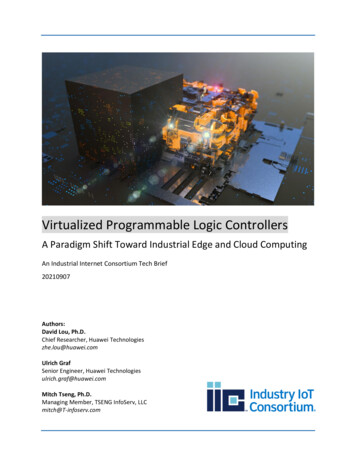
Chapter1Hardware OverviewHardware FeaturesThe Bulletin 1763, MicroLogix 1100 programmable controller containsa power supply, input and output circuits, a processor, an isolatedcombination RS-232/485 communication port, and an Ethernet port.Each controller supports 18 I/O points (10 digital inputs, 2 analoginputs, and 6 discrete outputs).The hardware features of the controller are shown below.Top ViewSide View121165847ESCOK392110Hardware t Terminal Block7LCD Keypad(ESC, OK, Up, Down, Left, Right)2Battery Connector8Status LED indicators3Bus Connector Interface to Expansion I/O9Memory Module Port Cover(1) -orMemory Module(2)4Battery10DIN Rail Latches5Input Terminal Block11RS-232/485 Communication Port(Channel 0, isolated)6LCD12Ethernet Port(Channel 1)(1)Shipped with controller.(2)Optional equipment.11Publication 1763-UM001B-EN-P - April 2007
12Hardware OverviewController Input Power and Embedded I/OCatalog DescriptionInput Power120/240V acDigital Inputs(10) 120V acAnalog Inputs(2) voltage inputDigital Outputs(6) relay120/240V ac(6) 24V dc0.10V dc(2) voltage inputAll individually isolated(6) relay0.10V dcAll individually isolated24V dc(4) high-speed 24V dc(1)(6) 24V dc(2) voltage input0.10V dc12.24V dc(4) high-speed 24V dc(1)(6) 12.24V dc(2) relay (isolated)(2) 24V dc FET(2) high-speed 24V dc FET(2) voltage input(6) relay(4) high-speed 12/24V dc(1) 0.10V dc(1)All individually isolatedThe 4 high-speed inputs (inputs 0 through 3) can be used individually for pulse catch/latching inputs or combined as a high speed counter. Refer to Digital InputSpecifications on page 161 and the MicroLogix 1100 Instruction Set Reference Manual, publication 1763-RM001, for more information.Component DescriptionsMicroLogix 1100 Memory Module and Built-in Real-Time ClockThe controller has a built-in real-time clock to provide a reference forapplications that need time-based control.The controller is shipped with a memory module port cover in place.You can order a memory module, 1763-MM1, as an accessory. Thememory module provides optional backup of your user program anddata, and is a means to transport your programs between controllers.The program and data in your MicroLogix 1100 is non-volatile and isstored when the power is lost to the controller. The memory moduleprovides additional backup that can be stored separately. The memorymodule does not increase the available memory of the controller.1763-MM1 Memory ModulePublication 1763-UM001B-EN-P - April 2007
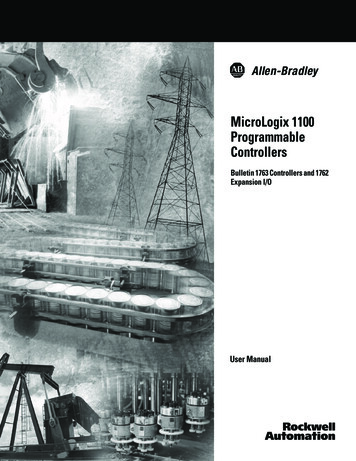
Hardware Overview131762 Expansion I/O1762 expansion I/O can be connected to the MicroLogix 1100controller, as shown below.TIPatA maximum of four I/O modules, in anycombination, can be connected to a controller. SeeAppendix G to determine how much heat a certaincombination generates.1762 Expansion I/O1762 Expansion I/O1762 Expansion I/O Connected to MicroLogix 1100 ControllerExpansion I/OCatalog NumberDescriptionDigital1762-IA88-Point 120V ac Input Module1762-IQ88-Point Sink/Source 24V dc Input Module1762-IQ1616-Point Sink/Source 24V dc Input Module1762-OA88-Point 120/240V ac Triac Output Module1762-OB88-Point Sourcing 24V dc Output Module1762-OB1616-Point Sourcing 24V dc Output Module1762-OW88-Point AC/DC Relay Output Module1762-OW1616-Point AC/DC Relay Output Module1762-OX6I6-Point Isolated AC/DC Relay Output Module1762-IQ8OW68-Point Sink/Source 24V dc Input and 6-Point AC/DC RelayOutput ModuleAnalog1762-IF44-Channel Voltage/Current Analog Input Module1762-OF44-Channel Voltage/Current Analog Output Module1762-IF2OF2Combination 2-Channel Input 2-Channel OutputVoltage/Current Analog ModulePublication 1763-UM001B-EN-P - April 2007
14Hardware OverviewExpansion I/OCatalog NumberDescriptionTemperatureCommunication Cables1762-IR44-Channel RTD/Resistance Input Module1762-IT44-Channel Thermocouple/mV Input ModuleUse only the following communication cables with the MicroLogix1100 controllers. These cables are required for Class I Div. 2applications. 1761-CBL-AM00 Series C or later1761-CBL-AP00 Series C or later1761-CBL-PM02 Series C or later1761-CBL-HM02 Series C or later2707-NC9 Series C or later1763-NC01 Series A or laterATTENTIONUNSUPPORTED CONNECTIONDo not connect a MicroLogix 1100 controller toanother MicroLogix family controller such asMicroLogix 1000, MicroLogix 1200, MicroLogix 1500,or the network port of a 1747-DPS1 Port Splitterusing a 1761- CBL-AM00 (8-pin mini-DIN to 8-pinmini-DIN) cable or equivalent.This type of connection will cause damage to theRS-232/485 communication port (Channel 0) of theMicroLogix 1100 and/or the controller itself. Thecommunication pins used for RS-485communications on the MicroLogix 1100 arealternately used for 24V power on the otherMicroLogix controllers and the network port of the1747-DPS1 Port Splitter.ProgrammingPublication 1763-UM001B-EN-P - April 2007Programming the MicroLogix 1100 controller is done using RSLogix500, Revision 7.0 or later. To use all of the latest features, RSLogix 500programming software must be version 7.20.00 or later.Communication cables for programming are available separately fromthe controller and software.
Hardware Overview15Firmware Revision HistoryFeatures are added to the controllers through firmware upgrades. Usethe listing below to be sure that your controller’s firmware is at thelevel you need. Firmware upgrades are not required, except to allowyou access to the new features.MicroLogix 1100CatalogNumberOS(1)SeriesLetterRelease DateOSOSRevision FirmwareRelease BBBAAFRN1August 2005Initial product release.ABFRN2October 2005According to the SRAM component, MicroLogix 1100 may causeHard-fault at the start of the Operating System in the very hightemperature environment. Corrected.ACFRN3February 2006Added Data file write feature through web server.BAFRN4February 2007 Direct connection to RS485 Network for DF1 half-duplexMaster driver.1763-L16AWA1763-L16BWA1763-L16BBB Direct connection to RS485 Network for DF1 half-duplex Slavedriver. Direct connection to RS485 Network for ASCII driver. Selectable Stop/Data Bits for Modbus Master RTU driver. Selectable Stop/Data Bits for Modbus Slave RTU driver. Selectable Stop/Data Bits for ASCII driver. Settable Inactivity Timeout feature for Ethernet driver. Unsolicited Ethernet messaging to RSLinx OPC topic. CIP Generic messaging through the Ethernet port. Unconnected Ethernet/IP protocol for Ethernet driver. IP conflict detection mechanism. E-mail feature. Ethernet MSG break bit. DNS functionality when E-mail feature is used. Change IP Address using Ethernet MSG instruction. ST file type for all PCCC commands. HSC (High Speed Counter) up to 40 KHz. PTO/PWM up to 40 KHz. 2-channel Analog Input Filter. Web View Disable for Data Files.1763-L16AWA1763-L16BWA1763-L16BBBBBFRN5May 2007 Improved system interrupt delay time.1763-L16DWDBBFRN5May 2007 Initial Product release. Supports all the features listed abovefor the 1763-L16AWA, 1763-L16BWA, and 1763-L16BBBcontrollers.(1)OS Operating System.Publication 1763-UM001B-EN-P - April 2007
16Hardware OverviewCommunication OptionsThe MicroLogix 1100 controllers provide two communications ports,an isolated combination RS-232/485 communication port (Channel 0)and an Ethernet port (Channel 1).The isolated Channel 0 port on the MicroLogix 1100 can be connectedto the following: operator interfaces, personal computers, etc. using DF1 FullDuplex point-to-point a DH-485 network a DF1 Radio Modem network a DF1 half-duplex network as an RTU Master or RTU Slave a Modbus network as an RTU Master or
programming, or troubleshooting control systems that use MicroLogix 1100 controllers. You should have a basic understanding of electrical circuitry and familiarity with relay logic. If you do not, obtain the proper training before using this product. Purpose of this Manual This manual