Transcription
Installation InstructionsMicroLogix 1400 Programmable ControllersCatalog Number(s) 1766-L32AWA, 1766-L32AWAA,1766-L32BWA, 1766-L32BWAA, 1766-L32BXB,1766-L32BXBATopicPageImportant User Information4Additional Resources7Overview8Controller Description9Hazardous Location Considerations11Mount the Controller13Connect 1762 I/O Expansion Modules18Wire the Controller19Specifications28
4MicroLogix 1400 Programmable ControllersImportant User InformationSolid state equipment has operational characteristics differing from those of electromechanical equipment.Safety Guidelines for the Application, Installation and Maintenance of Solid State Controls (PublicationSGI-1.1 available from your local Rockwell Automation sales office or online athttp://literature.rockwellautomation.com) describes some important differences between solid stateequipment and hard-wired electromechanical devices. Because of this difference, and also because of thewide variety of uses for solid state equipment, all persons responsible for applying this equipment mustsatisfy themselves that each intended application of this equipment is acceptable.In no event will Rockwell Automation, Inc. be responsible or liable for indirect or consequential damagesresulting from the use or application of this equipment.The examples and diagrams in this manual are included solely for illustrative purposes. Because of the manyvariables and requirements associated with any particular installation, Rockwell Automation, Inc. cannotassume responsibility or liability for actual use based on the examples and diagrams.No patent liability is assumed by Rockwell Automation, Inc. with respect to use of information, circuits,equipment, or software described in this manual.Reproduction of the contents of this manual, in whole or in part, without written permission of RockwellAutomation, Inc., is prohibited.Throughout this manual, when necessary, we use notes to make you aware of safety considerations.WARNINGIMPORTANTATTENTIONIdentifies information about practices or circumstances that can cause an explosion ina hazardous environment, which may lead to personal injury or death, propertydamage, or economic loss.Identifies information that is critical for successful application and understanding ofthe product.Identifies information about practices or circumstances that can lead to personal injuryor death, property damage, or economic loss. Attentions help you identify a hazard,avoid a hazard and recognize the consequences.SHOCK HAZARDLabels may be on or inside the equipment (for example, drive or motor) to alert peoplethat dangerous voltage may be present.BURN HAZARDLabels may be on or inside the equipment (for example, drive or motor) to alert peoplethat surfaces may reach dangerous temperatures.Publication 1766-IN001E-EN-P - April 2017
MicroLogix 1400 Programmable Controllers5Environment and EnclosureATTENTIONThis equipment is intended for use in a Pollution Degree 2 industrialenvironment, in overvoltage Category II applications (as defined in IECpublication 60664-1), at altitudes up to 2000 meters (6562 ft) without derating.This equipment is considered Group 1, Class A industrial equipment according toIEC/CISPR Publication 11. Without appropriate precautions, there may bepotential difficulties ensuring electromagnetic compatibility in otherenvironments due to conducted as well as radiated disturbance.This equipment is supplied as open-type equipment. It must be mounted withinan enclosure that is suitably designed for those specific environmentalconditions that will be present and appropriately designed to prevent personalinjury resulting from accessibility to live parts. The enclosure must have suitableflame-retardant properties to prevent or minimize the spread of flame,complying with a flame spread rating of 5VA, V2, V1, V0 (or equivalent) ifnon-metallic. The interior of the enclosure must be accessible only by the use ofa tool. Subsequent sections of this publication may contain additionalinformation regarding specific enclosure type ratings that are required to complywith certain product safety certifications.Preventing Electrostatic DischargeATTENTIONThis equipment is sensitive to electrostatic discharge, which can cause internaldamage and affect normal operation. Follow these guidelines when you handlethis equipment: Touch a grounded object to discharge potential static.Wear an approved grounding wriststrap.Do not touch connectors or pins on component boards.Do not touch circuit components inside the equipment.Use a static-safe workstation, if available.Store the equipment in appropriate static-safe packaging when not in use.Publication 1766-IN001E-EN-P - April 2017
6MicroLogix 1400 Programmable ControllersNorth American Hazardous Location ApprovalThe following modules are North American Hazardous Location approved: 1766-L32AWA,1766-L32AWAA, 1766-L32BWA, 1766-L32BWAA, 1766-L32BXB, 1766-L32BXBAThe following information applies whenoperating this equipment in hazardouslocations:Informations sur l’utilisation de cetéquipement en environnementsdangereux:Products marked "CL I, DIV 2, GP A, B, C, D" aresuitable for use in Class I Division 2 Groups A, B, C,D, Hazardous Locations and nonhazardous locationsonly. Each product is supplied with markings on therating nameplate indicating the hazardous locationtemperature code. When combining products withina system, the most adverse temperature code(lowest "T" number) may be used to help determinethe overall temperature code of the system.Combinations of equipment in your system aresubject to investigation by the local Authority HavingJurisdiction at the time of installation.Les produits marqués "CL I, DIV 2, GP A, B, C, D" neconviennent qu’à une utilisation en environnementsde Classe I Division 2 Groupes A, B, C, D dangereux etnon dangereux. Chaque produit est livré avec desmarquages sur sa plaque d’identification quiindiquent le code de température pour lesenvironnements dangereux. Lorsque plusieursproduits sont combinés dans un système, le code detempérature le plus défavorable (code de températurele plus faible) peut être utilisé pour déterminer le codede température global du système. Les combinaisonsd’équipements dans le système sont sujettes àinspection par les autorités locales qualifiées aumoment de l’installation.WARNINGEXPLOSION HAZARDAVERTISSEMENTRISQUE D’EXPLOSION Do not disconnect while thecircuit is live or unless the areais known to be free of ignitibleconcentrations. Couper le courant ou s’assurerque l’environnement est classénon dangereux avant dedébrancher l'équipement. Do not disconnect connectionsto this equipment unless powerhas been removed or the area isknown to be nonhazardous.Secure any external connectionsthat mate to this equipment byusing screws, sliding latches,threaded connectors, or othermeans provided with thisproduct. Couper le courant ou s'assurerque l’environnement est classénon dangereux avant dedébrancher les connecteurs. Fixertous les connecteurs externesreliés à cet équipement à l'aidede vis, loquets coulissants,connecteurs filetés ou autresmoyens fournis avec ce produit. Substitution of components mayimpair suitability for Class I,Division 2. Do not remove or replace lamps,fuses or plug-in modules (asapplicable) unless power hasbeen disconnected or the area isknown to be free of ignitibleconcentrations of flammablegases or vapors.Publication 1766-IN001E-EN-P - April 2017 La substitution de composantspeut rendre cet équipementinadapté à une utilisation enenvironnement de Classe I,Division 2. S’assurer que l’environnementest classé non dangereux avantde changer les piles.
MicroLogix 1400 Programmable Controllers7Additional ResourcesResourceDescriptionMicroLogix 1400 Programmable Controllers UserManual 1766-UM001A more detailed description of how to install and useyour MicroLogix 1400 programmable controller andexpansion I/O system.MicroLogix 1400 Instruction Set ReferenceManual 1766-RM001A reference manual that contains data and functionfiles, instruction set, and troubleshooting informationfor MicroLogix 1400.Installation Instructions 1762-INxxxInformation on installing and using 1762 expansion I/Omodules.Industrial Automation Wiring and GroundingGuidelines 1770-4.1More information on proper wiring and groundingtechniques.If you would like a manual, you can: download a free electronic version from the internet:http://literature.rockwellautomation.com purchase a printed manual by contacting your local Allen-Bradley distributor orRockwell Automation representativePublication 1766-IN001E-EN-P - April 2017
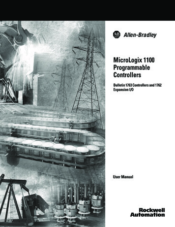
8MicroLogix 1400 Programmable ControllersOverviewMicroLogix 1400 controllers are suitable for use in an industrial environment when installedin accordance with these instructions. Specifically, this equipment is intended for use in clean,dry environments (Pollution degree 2(1)) and with circuits not exceeding Over VoltageCategory II(2) (IEC 60664-1)(3). AC powered products must be connected to the secondary ofan isolating transformer.Install your controller using these installation instructions.Debris strip44513ATTENTIONDo not remove the protective debris strip until after the controller and all otherequipment in the panel near the controller are mounted and wiring is complete.Once wiring is complete, remove protective debris strip. Failure to remove stripbefore operating can cause overheating.ATTENTIONElectrostatic discharge can damage semiconductor devices inside the controller.Do not touch the connector pins or other sensitive areas.(1)Pollution Degree 2 is an environment where, normally, only non-conductive pollution occurs except that occasionally atemporary conductivity caused by condensation shall be expected.(2)Over Voltage Category II is the load level section of the electrical distribution system. At this level transient voltages arecontrolled and do not exceed the impulse voltage capability of the product's insulation.(3)Pollution Degree 2 and Over Voltage Category II are International Electrotechnical commissions (IEC) designations.Publication 1766-IN001E-EN-P - April 2017
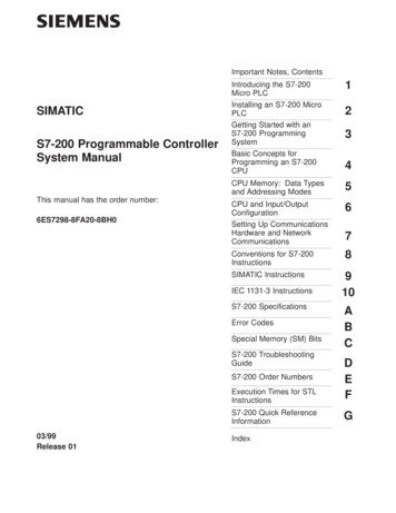
MicroLogix 1400 Programmable Controllers9Controller Description1 2 34567ESC1OK445141312 11Left side view109844515Top viewDescription1Comm port 2 - 9-pin D-Shell RS-232C connector2Memory module (refer to MicroLogix 1400 Memory Module Installation Instructions, publication1766-IN010 for instructions on installing the memory module).3User 24V (for 1766-L32BWA and 1766-L32BWAA only)4Input terminal block5LCD Display Keypad (ESC, OK, Up, Down, Left, Right)6Battery compartment71762 expansion bus connector8Battery connector9Output terminal block10LCD Display11Indicator LED panel12Comm port 1 - RJ45 connector13Comm port 0 - 8-pin mini DIN RS-232C/RS-485 connectorPublication 1766-IN001E-EN-P - April 2017
10MicroLogix 1400 Programmable ControllersController Input and Output L32BWAUserPowerEmbeddedDiscrete I/O24V DC12 Fast 24V DC Inputs8 Normal 24V DC Inputs12 Relay Outputs100/240V AC1766-L32AWA20 120V AC Inputs12 Relay Outputs1766-L32BXB12 Fast 24V DC Inputs8 Normal 24V DC Inputs6 Relay Outputs3 Fast DC Outputs3 Normal DC OutputsNone24 V DC1766-L32BWAA24V DC100/240V ACNone1766-L32BXBA24V DC12 Fast 24V DC Inputs8 Normal 24V DC Inputs6 Relay Outputs3 Fast DC Outputs3 Normal DC Outputs(1)Isolated RS-232/RS-485 combo port. Same as ML1100 Comm 0(2)Non-isolated RS-232. Standard D-sub connectorPublication 1766-IN001E-EN-P - April 2017Comm.PortsNone1 RS232/RS485(1)1 Ethernet/IP12 Fast 24V DC Inputs8 Normal 24V DC Inputs12 Relay Outputs20 120V AC Inputs12 Relay Outputs1766-L32AWAAEmbeddedAnalog I/O1 RS232(2)4 Voltage Inputs2 VoltageOutputs
MicroLogix 1400 Programmable Controllers11Hazardous Location ConsiderationsThis equipment is suitable for use in Class I, Division 2, Groups A, B, C, D or non-hazardouslocations only. The following WARNING statement applies to use in hazardous locations.WARNINGEXPLOSION HAZARD Substitution of components may impair suitability for Class I, Division 2. Do not replace components or disconnect equipment unless power has been switchedoff. Do not connect or disconnect components unless power has been switched off. This product must be installed in an enclosure. All cables connected to the productmust remain in the enclosure or be protected by conduit or other means. All wiring must comply with N.E.C. article 501-10(b) and/or in accordance withSection 18-1J2 of the Canadian Electrical Code, and in accordance with the authorityhaving jurisdiction.Use only the following communication cables in Class I, Division 2 hazardous locations.Environment ClassificationClass I, Division 2 Hazardous EnvironmentCommunication Cables1761-CBL-AC00 Series C or later1761-CBL-AM00 Series C or later1761-CBL-AP00 Series C or later1761-CBL-PM02 Series C or later1761-CBL-HM02 Series C or later2707-NC9 Series C or later1763-NC01 Series A or later1747-CP3 SeriesPublication 1766-IN001E-EN-P - April 2017
12MicroLogix 1400 Programmable ControllersEnvironnements dangereuxCet équipement est conçu pour une utilisation en environnements dangereux de Classe I,Division 2, Groupes A, B, C, D ou non dangereux. La mise en garde suivante s’applique àutilisation en environnements dangereux.WARNINGDANGER D’EXPLOSION La substitution de composants peut rendre cet équipement impropre à une utilisationen environnement de Classe I, Division 2. Ne pas remplacer de composants ou déconnecter l’équipement sans s’être assuré quel’alimentation est coupée. Ne pas connecter ou déconnecter des composants sans s’être assuré quel’alimentation est coupée. Ce produit doit être installé dans une armoire. Tous les câbles connectés à l’appareildoivent rester dans l’armoire ou être protégés par une goulotte ou tout autre moyen. L’ensemble du câblage doit être conforme à la réglementation en vigueur dans lespays où l’appareil est installé.Utilisez uniquement les câbles de communication suivants dans les environnementsdangereux de Classe I, Division 2.Classification des environnementsCâbles de communicationEnvironnement dangereux de Classe I, Division 21761-CBL-AC00 série C ou ultérieure1761-CBL-AM00 série C ou ultérieure1761-CBL-AP00 série C ou ultérieure1761-CBL-PM02 série C ou ultérieure1761-CBL-HM02 série C ou ultérieure2707-NC9 série C ou ultérieure1763-NC01 série A ou ultérieuresérie 1747-CP3ATTENTIONUNSUPPORTED CONNECTIONDo not connect the Comm0 port on the MicroLogix 1400 controller to another MicroLogixfamily controller such as MicroLogix 1000, MicroLogix 1200, or MicroLogix 1500 using a1761-CBL-AM00 (8-pin mini-DIN to 8-pin mini-DIN) cable or equivalent.This type of connection will cause damage to the RS-232/485 communication port(Channel 0) of the MicroLogix 1400 and/or the controller itself. Communication pins usedfor RS-485 communications are alternately used for 24V power on the other MicroLogixcontrollers.Publication 1766-IN001E-EN-P - April 2017
MicroLogix 1400 Programmable Controllers13Mount the ControllerGeneral ConsiderationsMost applications require installation in an industrial enclosure to reduce the effects ofelectrical interference and environmental exposure. Locate your controller as far as possiblefrom power lines, load lines, and other sources of electrical noise such as hard-contactswitches, relays, and ac motor drives. For more information on proper grounding guidelines,see the Industrial Automation Wiring and Grounding Guidelines, publication 1770-4.1.ATTENTIONMount the controller horizontally only. Vertical mounting is not supported due tothermal considerations.ATTENTIONBe careful of metal chips when drilling mounting holes for your controller orother equipment within the enclosure or panel. Drilled fragments that fall intothe controller could cause damage. Do not drill holes above a mounted controllerif the protective debris strips have been removed.WARNINGDo not place the MicroLogix 1400 Programmable Controller in direct sunlight.Prolonged exposure to direct sunlight could degrade the LCD display.WARNINGThe local programming terminal port is intended for temporary use only andmust not be connected or disconnected unless the area is assured to benonhazardous.Publication 1766-IN001E-EN-P - April 2017
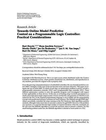
14MicroLogix 1400 Programmable ControllersMounting DimensionsCA44516B1766-L32BWA, 1766-L32AWA, 1766-L32BXB,1766-L32BWAA, 1766-L32AWAA, 1766-L32BXBADimensionHeightA90 mm (3.5 in.)B180 mm (7.087 in.)C87 mm (3.43 in.)Controller SpacingThe controller mounts horizontally, with the expansion I/O extending to the right of thecontroller. Allow 50 mm (2 in.) of space on all but the right side for adequate ventilation, asshown below.TopESCSideOKBottom44517Publication 1766-IN001E-EN-P - April 2017
MicroLogix 1400 Programmable Controllers15DIN Rail MountingThe maximum extension of the latch is 14 mm (0.55 in.) in the open position. A flat-bladescrewdriver is required for removal of the controller. The controller can be mounted toEN50022-35x7.5 or EN50022-35x15 DIN rails. DIN rail mounting dimensions are shownbelow.BAC44518DimensionHeightA90 mm (3.5 in.)B27.5 mm (1.08 in.)C27.5 mm (1.08 in.)Follow these steps to install your controller on the DIN rail.1. Mount your DIN rail. Make sure that the placement of the controller on the DIN railmeets the recommended spacing requirements (see Controller Spacing on page 14 formore information). Refer to the mounting template inside the back cover of thisdocument.2. If it is open, close the DIN latch.3. Hook the top slot over the DIN rail.4. While pressing the controller down against the top of the rail, snap the bottom of thecontroller into position.5. Leave the protective debris strip attached until you are finished wiring the controllerand any other devices.Follow these steps to remove your controller from the DIN rail.1. Place a flat-blade screwdriver in the DIN rail latch at the bottom of the controller.Publication 1766-IN001E-EN-P - April 2017
16MicroLogix 1400 Programmable Controllers2. Holding the controller, pry downward on the latch until the latch locks in the openposition.3. Repeat steps 1 and 2 for the second DIN rail latch.4. Unhook the top of the DIN rail slot from the rail.ESCOKOpenClosed4451944520Panel MountingMount to panel using #8 or M4 screws. Follow these steps to install your controller usingmounting screws.1. Remove the mounting template from inside the back cover of this document.2. Secure the template to the mounting surface. Make sure your controller is spacedproperly (see Controller Spacing on page 14 for more information).3. Drill holes through the template.4. Remove the mounting template.Mounting Template5. Mount the controller.6. Leave the protective debris stripin place until you are finishedwiring the controller and anyother devicesESCOK44521Publication 1766-IN001E-EN-P - April 2017
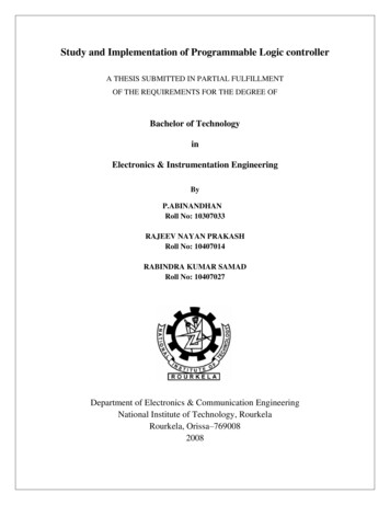
MicroLogix 1400 Programmable Controllers17Using the BatteryThe MicroLogix 1400 controller is equipped with a replaceable battery (catalog number1747-BA). The Battery Low indicator on the LCD display of the controller shows the statusof the replaceable battery. When the battery is low, the indicator is set (displayed as a solidrectangle). This means that either the battery wire connector is disconnected, or the batterymay fail within 2 days if it is connected.IMPORTANTWARNINGThe MicroLogix 1400 controller ships with the battery wire connector connected.Ensure that the battery wire connector is inserted into the connector port if yourapplication needs battery power. For example, when using a real-time clock(RTC).Replacing the battery when the controller is powered down will lose all userapplication memory. Replace the battery when the controller is powered on.Refer to the SLC 500 Lithium Battery Installation Instructions, publication1747-IN515, for more information on installation, handling, usage, storage, anddisposal of the battery.When you connect or disconnect the battery an electrical arc can occur. Thiscould cause an explosion in hazardous location installations. Be sure that thearea is nonhazardous before proceeding.For Safety information on the handling of lithium batteries, including handlingand disposal of leaking batteries, see Guidelines for Handling Lithium Batteries,publication AG 5-4.Follow these steps to connect the replaceable battery.1. Insert the replaceable battery wire connector into the controller’s battery connector.Publication 1766-IN001E-EN-P - April 2017
18MicroLogix 1400 Programmable Controllers2. Secure the battery connector wires so that it does not block the 1762 expansion busconnector as shown below.Battery compartmentBattery1762 I/Oexpansion busconnectorBattery wireconnectorBattery connectorBattery wirestwisted pair44522Connect 1762 I/O Expansion ModulesATTENTIONRemove power from the system before installing or removing expansion I/O or damage tothe controller may result.Connect 1762 I/O after mounting the controller.1. Remove the expansion port cover to install expansion I/O modules.2. Plug the ribbon cable connector into the bus connector.Publication 1766-IN001E-EN-P - April 2017
MicroLogix 1400 Programmable Controllers193. Replace the cover as shown below.44523The MicroLogix 1400 controller is designed to support up to any seven 1762 expansion I/Omodules.For detailed information on using expansion I/O, refer to the installation instructions foryour expansion module.Wire the ControllerThe shading in the following terminal block illustrations indicates which terminal groups aretied to which commons.Terminal Block LayoutsWARNINGWARNINGWhen you connect or disconnect the Removable Terminal Block (RTB) with fieldside power applied, an electrical arc can occur. This could cause an explosion inhazardous location installations. Be sure that power is removed or the area isnonhazardous before proceeding.When used in a Class I, Division 2, hazardous location, this equipment must bemounted in a suitable enclosure. All wiring must be in accordance with Class I,Division 2 wiring methods of Article 501 of the National Electrical Code and/orin accordance with Section 18-1J2 of the Canadian Electrical Code, and inaccordance with the authority having jurisdiction.Publication 1766-IN001E-EN-P - April 2017
20MicroLogix 1400 Programmable Controllers1766-L32BWA/L32BWAAInput Terminal BlockIN0COM 0VACL1COM 1IN2IN1IN3VACL2/NOUT0IN5IN6OUT1OUT2Group 0DC2VACGroup 1 Group 2IN8IN9OUT3DC3VACCOM 3IN10COM 2IN4DC1VACDC0VACIN7IN11Group 3OUT5IN17IN14IN16OUT7OUT8OUT10DC6VACOUT6Group 4IN15IN12VACDC5OUT4DC4VACIN13Group 5OUT9IN19IN18COMANACOMANAOUT11IV0( )IV2( )IV1( )IV3( )OV1OV0Group 644524Output Terminal Block1766-L32AWA/L32AWAAInput Terminal BlockIN0COM 0VACL1COM 1IN2IN1IN3VACL2/NOUT0IN5IN7IN8COM p 0Group 1Group 2Group 3COM 3IN10IN11OUT4DC4VACOUT5Group Group 5Output Terminal BlockPublication 1766-IN001E-EN-P - April 2017IN17OUT9Group 6IN19IN18OUT11IV0( )COMANACOMANAIV2( )IV1( )IV3( )OV1OV044525
MicroLogix 1400 Programmable Controllers211766-L32BXB/L32BXBAInput Terminal BlockIN0COM 0VDC 24COM 1IN2IN1IN3VDCNEUTOUT0IN5IN7IN6OUT1OUT2DC1VACGroup 0Group 1VDC2OUT4OUT3COM 3IN10COM M 2OUT8OUT9OUT10OUT5OUT7Group 2DC3VACDC4VACGroup 3Group 4DC5VACIN19IN18OUT11IV0( )COMANACOMANAIV2( )IV1( )IV3( )OV1OV0Group 544526Wire TypeWire SizeSolid wireCu-90 C (194 F)14 22 AWGStranded wireCu-90 C (194 F)16 22 AWGWiring torque 0.791Nm (7 in-lb) rated.Output Terminal GroupingOutputsControllerOutput GroupDescriptionVoltage TerminalOutput Terminal1766-L32BWA1766--L32BWAAGroup 0Isolated relay outputVAC/DC0OUT 0Group 1Isolated relay outputVAC/DC1OUT 1Group 2Isolated relay outputVAC/DC2OUT 2Group 3Isolated relay outputVAC/DC3OUT 3Group 4Isolated relay outputVAC/DC4OUT 4, OUT 5Group 5Isolated relay outputVAC/DC5OUT 6, OUT 7Group 6Isolated relay outputVAC/DC6OUT 8 11Publication 1766-IN001E-EN-P - April 2017
22MicroLogix 1400 Programmable ControllersOutput Terminal GroupingOutputsControllerOutput GroupDescriptionVoltage TerminalOutput Terminal1766-L32AWA1766-L32AWAAGroup 0Isolated relay outputVAC/DC0OUT 0Group 1Isolated relay outputVAC/DC1OUT 1Group 2Isolated relay outputVAC/DC2OUT 2Group 3Isolated relay outputVAC/DC3OUT 3Group 4Isolated relay outputVAC/DC4OUT 4, OUT 5Group 5Isolated relay outputVAC/DC5OUT 6, OUT 7Group 6Isolated relay outputVAC/DC6OUT 8 11Group 0Isolated relay outputVAC/DC0OUT 01766-L32BXB1766-L32BXBAWARNINGWARNINGGroup 1Isolated relay outputVAC/DC1OUT 1Group 2FET outputVDC2/COM 2OUT 2 7Group 3Isolated relay outputVAC/DC3OUT 8Group 4Isolated relay outputVAC/DC4OUT 9Group 5Isolated relay outputVAC/DC5OUT 10, OUT 11If you connect or disconnect wiring while the field-side power is on, an electricalarc can occur. This could cause an explosion in hazardous location installations.Be sure that power is removed or the area is nonhazardous before proceedingThe local programming terminal port is intended for temporary use only andmust not be connected or disconnected unless the area is free of ignitableconcentrations of flammable gases or vapors.Publication 1766-IN001E-EN-P - April 2017
MicroLogix 1400 Programmable Controllers23Wiring RecommendationWhen wiring without spade lugs, keep the finger-safe covers in place. Loosen the terminalscrew and route the wires through the opening in the finger-safe cover. Tighten the terminalscrew, making sure the pressure plate secures the wire.Finger-safe cover44527ATTENTIONBe careful when stripping wires. Wire fragments that fall into the controllercould cause damage. Once wiring is complete, be sure the controller is free ofall metal fragments before removing the protective debris strip. Failure toremove the strip before operating can cause overheating.Publication 1766-IN001E-EN-P - April 2017
24MicroLogix 1400 Programmable ControllersSpade Lug RecommendationThe diameter of the terminal screw head is 5.5 mm (0.220 in.). The input and outputterminals of the MicroLogix 1400 controller are designed for the following spade lugs. Theterminals will accept a 6.35mm (0.25 in.) wide spade (standard for #6 screw for up to 14AWG) or a 4 mm (metric #4) fork terminal.When using spade lugs, use a small, flat-blade screwdriver to pry the finger-safe cover fromthe terminal blocks, then loosen the terminal screw.Finger-safe cover44528TIPIf you wire the terminal block with the finger-safe cover removed, you may notbe able to put it back on the terminal block if the wires are in the way.Surge SuppressionATTENTIONInductive load devices such as motor starters and solenoids require the use ofsome type of surge suppression to protect the controller output. Switchinginductive loads without surge suppression can significantly reduce the life ofrelay contacts or damage transistor outputs. By using suppression, you alsoreduce the effects of voltage transients caused by interrupting the current tothat inductive device, and prevent electrical noise from radiating into systemwiring. Refer to the MicroLogix 1400 Programmable Controller User Manual,publication 1766-UM001, for more information on surge suppression.Publication 1766-IN001E-EN-P - April 2017
MicroLogix 1400 Programmable Controllers25Grounding the ControllerIn solid-state control systems, grounding and wire routing helps limit the effects of noise dueto electromagnetic interference (EMI). Run the ground connection from the ground screw ofthe controller to the ground bus prior to connecting any devices. Use AWG #14 wire. ForAC-powered controllers, this connection must be made for safety purposes.You must also provide an acceptable grounding path for each device in your application. Formore information on proper grounding guidelines, refer to the Industrial Automation Wiringand Grounding Guidelines, publication 1770-4.1.Wiring Your Analog ChannelsAnalog input circuits can monitor voltage signals and convert them to serial digital data asshown in the following illustration.Analog InputSensor 2(V) VoltageSensor 0(V) VoltageInput Terminal Block/7I/8COM 2COM 3I/10I/9I/11I/13I/12I/15I/14I/17I/16I/19I/18IV0( )COMANAIV2( )IV1( )IV3( )Sensor 1(V) VoltageSensor 3(V) Voltage44529Publication 1766-IN001E-EN-P - April 2017
26MicroLogix 1400 Programmable ControllersThe controller does not provide loop power for analog inputs. Use a power supply thatmatches the transmitter specifications as shown.The analog output can support a voltage function as shown in the following illustration.Analog OutputVoltage 10O/9O/11OV1OV0Output Terminal BlockVoltage Load44680Analog Input Transmitter Specifications2-Wire Transmitter 3-Wire TransmitterPowerSupply -TransmitterSignalSupplyGND -4-Wire TransmitterPowerSupplyTransmitter -TransmitterSignalSupply - -ControllerIV0( ), IV1( ), IV2( ) or IV3( )COM ANAControllerIV0( ), IV1( ), IV2( ) or IV3( )COM ANAControllerIV0( ), IV1( ), IV2( ) or IV3( )COM ANA44530Publication 1766-IN001E-EN-P - April 2017
MicroLogix 1400 Programmable Controllers27Minimizing Electrical Noise on Analog ChannelsInputs on analog channels employ digital high-frequency filters that significantly reduce theeffects of electrical noise on input signals. However, because of the variety of applications andenvironments where analog controllers are installed and operated, it is impossible to ensurethat all environmental noise will be removed by the input filters.Several specific steps can be taken to help reduce the effects of environmental noise onanalog signals: Install the MicroLogix 1400 system in a properly rated (NEMA) enclosure. Make surethat the MicroLogix 1400 system is properly grounded. Use Belden cable #8761 for wiring the analog channels, making sure that the drainwire and foil shield are properly earth grounded, (see Grounding Your Analog Cableon page 27 for more information). Route the Belden cable
MicroLogix 1400 Programmable Controllers Catalog Number(s) 1766-L32AWA, 1766-L32AWAA, 1766-L32BWA, 1766-L32BWAA, 1766-L32BXB, 1766-L32BXBA Topic Page Important User Information 4 Additional Resources 7 Overview 8 Controller Description 9 Hazardous Location Considerations 11 Mount the Controller 13 Connect 1762 I/O Expansion Modules 18 Wire the .