Transcription
efesotomasyon.com - Allen Bradley,Rockwell,plc,servo,driveMicroLogix 1200ProgrammableControllersBulletin 1762 Controllers andExpansion I/OUser Manual
efesotomasyon.com - Allen Bradley,Rockwell,plc,servo,driveImportant User InformationSolid state equipment has operational characteristics differing from those ofelectromechanical equipment. Safety Guidelines for the Application, Installation andMaintenance of Solid State Controls publication SGI-1.1 available from your localRockwell Automation sales office or online athttp://www.literature.rockwellautomation.com describes some important differencesbetween solid state equipment and hard-wired electromechanical devices. Because ofthis difference, and also because of the wide variety of uses for solid state equipment,all persons responsible for applying this equipment must satisfy themselves that eachintended application of this equipment is acceptable.In no event will Rockwell Automation, Inc. be responsible or liable for indirect orconsequential damages resulting from the use or application of this equipment.The examples and diagrams in this manual are included solely for illustrative purposes.Because of the many variables and requirements associated with any particularinstallation, Rockwell Automation, Inc. cannot assume responsibility or liability foractual use based on the examples and diagrams.No patent liability is assumed by Rockwell Automation, Inc. with respect to use ofinformation, circuits, equipment, or software described in this manual.Reproduction of the contents of this manual, in whole or in part, without writtenpermission of Rockwell Automation, Inc. is prohibited.Throughout this manual we use notes to make you aware of safety considerations.WARNINGIMPORTANTATTENTIONIdentifies information about practices or circumstancesthat can cause an explosion in a hazardous environment,which may lead to personal injury or death, propertydamage, or economic loss.Identifies information that is critical for successfulapplication and understanding of the product.Identifies information about practices or circumstancesthat can lead to personal injury or death, propertydamage, or economic loss. Attentions help you: identify a hazard avoid a hazard recognize the consequencePublication 1762-UM001F-EN-P - January 2010SHOCK HAZARDLabels may be located on or inside the drive to alertpeople that dangerous voltage may be present.BURN HAZARDLabels may be located on or inside the drive to alertpeople that surfaces may be dangerous temperatures.
efesotomasyon.com - Allen Bradley,Rockwell,plc,servo,driveSummary of ChangesTo help you find new and updated information in this release of the manual,we have included change bars as shown to the right of this paragraph.Firmware Revision History1Features are added to the controllers through firmware upgrades. See the latestrelease notes, 1762-RN001, to be sure that your controller’s firmware is at thelevel you need. Firmware upgrades are not required, except to allow you accessto the new features.Publication 1762-UM001F-EN-P - January 2010
efesotomasyon.com - Allen Bradley,Rockwell,plc,servo,driveSummary of Changes2Notes:Publication 1762-UM001F-EN-P - January 2010
efesotomasyon.com - Allen Bradley,Rockwell,plc,servo,driveTable of ContentsPrefaceWho Should Use This Manual. . . . . . . . . . . . . . . . . . . . . . . . . . . . . . .Purpose of This Manual. . . . . . . . . . . . . . . . . . . . . . . . . . . . . . . . . . . .Related Documentation. . . . . . . . . . . . . . . . . . . . . . . . . . . . . . . . .Common Techniques Used in This Manual . . . . . . . . . . . . . . . . . . . .P-1P-1P-2P-2Chapter 1Hardware OverviewHardware Features . . . . . . . . . . . . . . . . . . . . . . . . . . . . . . . . . . . . . . . .Component Descriptions. . . . . . . . . . . . . . . . . . . . . . . . . . . . . . . . . . .MicroLogix 1200 Memory Module and/or Real-time Clock. . . .1762 Expansion I/O . . . . . . . . . . . . . . . . . . . . . . . . . . . . . . . . . . .Communication Cables . . . . . . . . . . . . . . . . . . . . . . . . . . . . . . . . . . . .Program the Controller . . . . . . . . . . . . . . . . . . . . . . . . . . . . . . . . . . . .Communication Options . . . . . . . . . . . . . . . . . . . . . . . . . . . . . . . . . . .1-11-21-21-31-41-41-4Chapter 2Install Your ControlleriRequired Tools . . . . . . . . . . . . . . . . . . . . . . . . . . . . . . . . . . . . . . . . . . . 2-1Agency Certifications . . . . . . . . . . . . . . . . . . . . . . . . . . . . . . . . . . . . . . 2-1Compliance to European Union Directives . . . . . . . . . . . . . . . . . . . . 2-2EMC Directive. . . . . . . . . . . . . . . . . . . . . . . . . . . . . . . . . . . . . . . . 2-2Low Voltage Directive. . . . . . . . . . . . . . . . . . . . . . . . . . . . . . . . . . 2-2Installation Considerations . . . . . . . . . . . . . . . . . . . . . . . . . . . . . . . . . 2-2Safety Considerations. . . . . . . . . . . . . . . . . . . . . . . . . . . . . . . . . . . . . . 2-3Hazardous Location Considerations. . . . . . . . . . . . . . . . . . . . . . . 2-3Disconnect Main Power . . . . . . . . . . . . . . . . . . . . . . . . . . . . . . . . 2-4Safety Circuits. . . . . . . . . . . . . . . . . . . . . . . . . . . . . . . . . . . . . . . . . 2-4Power Distribution . . . . . . . . . . . . . . . . . . . . . . . . . . . . . . . . . . . . 2-5Periodic Tests of Master Control Relay Circuit . . . . . . . . . . . . . . 2-5Power Considerations . . . . . . . . . . . . . . . . . . . . . . . . . . . . . . . . . . . . . 2-5Isolation Transformers . . . . . . . . . . . . . . . . . . . . . . . . . . . . . . . . . 2-5Power Supply Inrush . . . . . . . . . . . . . . . . . . . . . . . . . . . . . . . . . . . 2-6Loss of Power Source . . . . . . . . . . . . . . . . . . . . . . . . . . . . . . . . . . 2-6Input States on Power Down . . . . . . . . . . . . . . . . . . . . . . . . . . . . 2-6Other Types of Line Conditions . . . . . . . . . . . . . . . . . . . . . . . . . . 2-7Prevent Excessive Heat . . . . . . . . . . . . . . . . . . . . . . . . . . . . . . . . . . . . 2-7Master Control Relay . . . . . . . . . . . . . . . . . . . . . . . . . . . . . . . . . . . . . . 2-8Use Emergency-Stop Switches . . . . . . . . . . . . . . . . . . . . . . . . . . . 2-9Schematic (Using IEC Symbols) . . . . . . . . . . . . . . . . . . . . . . . . . 2-10Schematic (Using ANSI/CSA Symbols). . . . . . . . . . . . . . . . . . . 2-11Install a Memory Module or Real-time Clock. . . . . . . . . . . . . . . . . . 2-12Controller Mounting Dimensions . . . . . . . . . . . . . . . . . . . . . . . . . . . 2-13Controller andExpansion I/O Spacing . . . . . . . . . . . . . . . . . . . . . . . . . . . . . . . . . . . 2-13Mount the Controller . . . . . . . . . . . . . . . . . . . . . . . . . . . . . . . . . . . . . 2-14DIN Rail Mounting . . . . . . . . . . . . . . . . . . . . . . . . . . . . . . . . . . . 2-15Panel Mounting . . . . . . . . . . . . . . . . . . . . . . . . . . . . . . . . . . . . . . 2-161762 Expansion I/O Dimensions. . . . . . . . . . . . . . . . . . . . . . . . . . . 2-17Publication 1762-UM001F-EN-P - January 2010
efesotomasyon.com - Allen Bradley,Rockwell,plc,servo,driveTable of ContentsiiMount 1762Expansion I/O . . . . . . . . . . . . . . . . . . . . . . . . . . . . . . . . . . . . . . . . . .DIN Rail Mounting . . . . . . . . . . . . . . . . . . . . . . . . . . . . . . . . . . .Mount on Panel . . . . . . . . . . . . . . . . . . . . . . . . . . . . . . . . . . . . . .Connect Expansion I/O . . . . . . . . . . . . . . . . . . . . . . . . . . . . . . . . . .2-172-172-182-19Chapter 3Wire Your ControllerWire Requirements. . . . . . . . . . . . . . . . . . . . . . . . . . . . . . . . . . . . . . . . 3-1Wire without Spade Lugs. . . . . . . . . . . . . . . . . . . . . . . . . . . . . . . . 3-2Wire with Spade Lugs . . . . . . . . . . . . . . . . . . . . . . . . . . . . . . . . . . 3-3Use Surge Suppressors . . . . . . . . . . . . . . . . . . . . . . . . . . . . . . . . . . . . . 3-3Recommended Surge Suppressors . . . . . . . . . . . . . . . . . . . . . . . . 3-5Ground the Controller . . . . . . . . . . . . . . . . . . . . . . . . . . . . . . . . . . . . . 3-6Wiring Diagrams . . . . . . . . . . . . . . . . . . . . . . . . . . . . . . . . . . . . . . . . . 3-7Terminal Block Layouts. . . . . . . . . . . . . . . . . . . . . . . . . . . . . . . . . 3-7Terminal Groupings . . . . . . . . . . . . . . . . . . . . . . . . . . . . . . . . . . . 3-9Sinking and Sourcing Wiring Diagrams . . . . . . . . . . . . . . . . . . . . . . 3-121762-L24AWA, 1762-L24BWA, 1762-L24BXB,1762-L24AWAR, 1762-L24BWAR and 1762-L24BXBRWiring Diagrams . . . . . . . . . . . . . . . . . . . . . . . . . . . . . . . . . . . . . 3-121762-L40AWA, 1762-L40BWA, 1762-L40BXB,1762-L40AWAR, 1762-L40BWAR and 1762-L40BXBRWiring Diagrams . . . . . . . . . . . . . . . . . . . . . . . . . . . . . . . . . . . . . 3-15Controller I/O Wiring . . . . . . . . . . . . . . . . . . . . . . . . . . . . . . . . . . . . 3-17Minimize Electrical Noise . . . . . . . . . . . . . . . . . . . . . . . . . . . . . . 3-17Expansion I/O Wiring. . . . . . . . . . . . . . . . . . . . . . . . . . . . . . . . . . . . 3-18Discrete Wiring Diagrams . . . . . . . . . . . . . . . . . . . . . . . . . . . . . . 3-18Analog Wiring . . . . . . . . . . . . . . . . . . . . . . . . . . . . . . . . . . . . . . . 3-25Chapter 4Communication ConnectionsPublication 1762-UM001F-EN-P - January 2010Introduction . . . . . . . . . . . . . . . . . . . . . . . . . . . . . . . . . . . . . . . . . . . . . 4-1Supported Communication Protocols. . . . . . . . . . . . . . . . . . . . . . . . . 4-1Default Communication Configuration . . . . . . . . . . . . . . . . . . . . . . . 4-2Use the Communications Toggle Push Button . . . . . . . . . . . . . . . . . 4-3Connect to the RS-232 Port . . . . . . . . . . . . . . . . . . . . . . . . . . . . . . . . 4-4Make a DF1 Point-to-Point Connection . . . . . . . . . . . . . . . . . . . 4-5Use a Modem . . . . . . . . . . . . . . . . . . . . . . . . . . . . . . . . . . . . . . . . . 4-5Isolated Modem Connection. . . . . . . . . . . . . . . . . . . . . . . . . . . . . 4-6Connect to a DF1 Half-duplex Network . . . . . . . . . . . . . . . . . . . 4-8Connect to a DH-485 Network. . . . . . . . . . . . . . . . . . . . . . . . . . . . . . 4-9Recommended Tools. . . . . . . . . . . . . . . . . . . . . . . . . . . . . . . . . . . 4-9DH-485 Communication Cable . . . . . . . . . . . . . . . . . . . . . . . . . 4-10Connect the Communication Cable to the DH-485Connector. . . . . . . . . . . . . . . . . . . . . . . . . . . . . . . . . . . . . . . . . . . 4-10Ground and Terminate the DH-485 Network. . . . . . . . . . . . . . 4-12
efesotomasyon.com - Allen Bradley,Rockwell,plc,servo,driveTable of ContentsiiiConnect the AIC . . . . . . . . . . . . . . . . . . . . . . . . . . . . . . . . . . . . . . .Cable Selection Guide . . . . . . . . . . . . . . . . . . . . . . . . . . . . . . . . .Recommended User-supplied Components. . . . . . . . . . . . . . . .Safety Considerations . . . . . . . . . . . . . . . . . . . . . . . . . . . . . . . . .Install and Attach the AIC . . . . . . . . . . . . . . . . . . . . . . . . . . . .Apply Power to the AIC . . . . . . . . . . . . . . . . . . . . . . . . . . . . . .DeviceNet Communications . . . . . . . . . . . . . . . . . . . . . . . . . . . . . . .Cable Selection Guide . . . . . . . . . . . . . . . . . . . . . . . . . . . . . . . . .4-124-134-154-174-174-174-194-19Chapter 5Use Trim PotsTrim Pot Operation . . . . . . . . . . . . . . . . . . . . . . . . . . . . . . . . . . . . . . . 5-1Trim Pot Information Function File . . . . . . . . . . . . . . . . . . . . . . 5-2Error Conditions . . . . . . . . . . . . . . . . . . . . . . . . . . . . . . . . . . . . . . 5-2Chapter 6Use Real-time Clock and Memory Real-time Clock Operation . . . . . . . . . . . . . . . . . . . . . . . . . . . . . . . . . 6-1Removal/Insertion Under Power . . . . . . . . . . . . . . . . . . . . . . . . . 6-1ModulesWrite Data to the Real-time Clock . . . . . . . . . . . . . . . . . . . . . . . .RTC Battery Operation . . . . . . . . . . . . . . . . . . . . . . . . . . . . . . . . .Memory Module Operation. . . . . . . . . . . . . . . . . . . . . . . . . . . . . . . . .User Program and Data Back-up . . . . . . . . . . . . . . . . . . . . . . . . .Program Compare . . . . . . . . . . . . . . . . . . . . . . . . . . . . . . . . . . . . .Data File Download Protection . . . . . . . . . . . . . . . . . . . . . . . . . .Memory Module Write Protection . . . . . . . . . . . . . . . . . . . . . . . .Removal/Insertion Under Power . . . . . . . . . . . . . . . . . . . . . . . . .6-26-26-36-36-46-46-46-4Appendix ASpecificationsController Specifications . . . . . . . . . . . . . . . . . . . . . . . . . . . . . . . . . . A-1Expansion I/O Specifications . . . . . . . . . . . . . . . . . . . . . . . . . . . . . . A-8Discrete I/O Modules . . . . . . . . . . . . . . . . . . . . . . . . . . . . . . . . . A-8Analog Modules . . . . . . . . . . . . . . . . . . . . . . . . . . . . . . . . . . . . . A-15Combination Module DC-Input/Relay Output. . . . . . . . . . . . A-23Appendix B1762 Replacement PartsMicroLogix 1200 RTB Replacement Kit . . . . . . . . . . . . . . . . . . . . . . B-1Appendix CTroubleshoot Your SystemInterpret LED Indicators. . . . . . . . . . . . . . . . . . . . . . . . . . . . . . . . . . . C-1Normal Operation . . . . . . . . . . . . . . . . . . . . . . . . . . . . . . . . . . . . . C-2Error Conditions . . . . . . . . . . . . . . . . . . . . . . . . . . . . . . . . . . . . . . C-2Controller Error Recovery Model . . . . . . . . . . . . . . . . . . . . . . . . . . . . C-3Analog Expansion I/O Diagnostics and Troubleshooting . . . . . . . . C-4Module Operation and Channel Operation . . . . . . . . . . . . . . . . . C-4Power-up Diagnostics . . . . . . . . . . . . . . . . . . . . . . . . . . . . . . . . . . C-4Publication 1762-UM001F-EN-P - January 2010
efesotomasyon.com - Allen Bradley,Rockwell,plc,servo,driveTable of ContentsivCritical and Noncritical Errors . . . . . . . . . . . . . . . . . . . . . . . . . . . C-5Module Error Definition Table. . . . . . . . . . . . . . . . . . . . . . . . . . . C-5Error Codes . . . . . . . . . . . . . . . . . . . . . . . . . . . . . . . . . . . . . . . . . . C-7Call Rockwell Automation for Assistance. . . . . . . . . . . . . . . . . . . . . . C-8Appendix DUse Control Flash to Upgrade Your Prepare for Upgrade. . . . . . . . . . . . . . . . . . . . . . . . . . . . . . . . . . . . . . D-1Install ControlFlash Software . . . . . . . . . . . . . . . . . . . . . . . . . . . D-1Operating SystemPrepare the Controller for Updating. . . . . . . . . . . . . . . . . . . . . . D-2Sequence of Operation . . . . . . . . . . . . . . . . . . . . . . . . . . . . . . . . . . . D-2Missing/Corrupt OS LED Pattern . . . . . . . . . . . . . . . . . . . . . . . . . . D-2Appendix EConnect to Networks via RS-232InterfaceRS-232 Communication Interface . . . . . . . . . . . . . . . . . . . . . . . . . . . . E-1DF1 Full-duplex Protocol . . . . . . . . . . . . . . . . . . . . . . . . . . . . . . . . . . E-1DF1 Half-duplex Protocol. . . . . . . . . . . . . . . . . . . . . . . . . . . . . . . . . . E-2Use Modems with MicroLogix 1200 ProgrammableControllers . . . . . . . . . . . . . . . . . . . . . . . . . . . . . . . . . . . . . . . . . . . E-3DH-485 Communication Protocol . . . . . . . . . . . . . . . . . . . . . . . . . . . E-5Devices that use the DH-485 Network . . . . . . . . . . . . . . . . . . . . E-5Important DH-485 Network Planning Considerations . . . . . . . . E-6Example DH-485 Connections. . . . . . . . . . . . . . . . . . . . . . . . . . . E-9Modbus Communication Protocol . . . . . . . . . . . . . . . . . . . . . . . . . . E-12ASCII . . . . . . . . . . . . . . . . . . . . . . . . . . . . . . . . . . . . . . . . . . . . . . . . . E-12Appendix FSystem Loading and HeatDissipationGlossaryIndexPublication 1762-UM001F-EN-P - January 2010System Loading Limitations. . . . . . . . . . . . . . . . . . . . . . . . . . . . . . . . . F-1System Current Loading Example Calculations(24-point Controller) . . . . . . . . . . . . . . . . . . . . . . . . . . . . . . . . . . . F-1Validate the System . . . . . . . . . . . . . . . . . . . . . . . . . . . . . . . . . . . . F-2System Loading Worksheet . . . . . . . . . . . . . . . . . . . . . . . . . . . . . . . . . F-4Current Loading . . . . . . . . . . . . . . . . . . . . . . . . . . . . . . . . . . . . F-4System Current Loading Example Calculations(40-point Controller) . . . . . . . . . . . . . . . . . . . . . . . . . . . . . . . . . . . F-6System Loading Worksheet . . . . . . . . . . . . . . . . . . . . . . . . . . . . . . . . . F-8Current Loading. . . . . . . . . . . . . . . . . . . . . . . . . . . . . . . . . . . . . . . F-8Calculating Heat Dissipation . . . . . . . . . . . . . . . . . . . . . . . . . . . . . . . F-10
efesotomasyon.com - Allen Bradley,Rockwell,plc,servo,drivePrefaceRead this preface to familiarize yourself with the rest of the manual. It providesinformation concerning: Who Should Use ThisManualwho should use this manualthe purpose of this manualrelated documentationconventions used in this manualUse this manual if you are responsible for designing, installing, programming,or troubleshooting control systems that use MicroLogix 1200 controllers.You should have a basic understanding of electrical circuitry and familiaritywith relay logic. If you do not, obtain the proper training before using thisproduct.Purpose of This ManualThis manual is a reference guide for MicroLogix 1200 controllers andexpansion I/O. It describes the procedures you use to install, wire, andtroubleshoot your controller. This manual: explains how to install and wire your controllers gives you an overview of the MicroLogix 1200 controller systemRefer to publication 1762-RM001, MicroLogix 1200 and 1500 ProgrammableControllers Instruction Set Reference Manual, for the MicroLogix 1200 and1500 instruction set and for application examples to show the instruction setin use. Refer to your RSLogix 500 programming software user documentationfor more information on programming your MicroLogix 1200 controller.1Publication 1762-UM001F-EN-P - January 2010
efesotomasyon.com - Allen Bradley,Rockwell,plc,servo,driveP-2PrefaceRelated DocumentationThe following documents contain additional information concerning RockwellAutomation products. To obtain a copy, contact your localRockwell Automation office or distributor.ResourceDescriptionMicroLogix 1200 and 1500 Programmable ControllersInstruction Set Reference Manual, publication1762-RM001Information on the MicroLogix 1200 Controllers instruction set.MicroLogix 1200 Programmable Controllers InstallationInstructions, publication 1762-IN006Information on mounting and wiring the MicroLogix 1200 Controllers, includinga mounting template for easy installation.Advanced Interface Converter (AIC ) User Manual,publication 1761-UM004A description on how to install and connect an AIC . This manual alsocontains information on network wiring.DeviceNet Interface User Manual, publication1761-UM005Information on how to install, configure, and commission a DNI.DF1 Protocol and Command Set Reference Manual,publication 1770-6.5.16Information on DF1 open protocol.Modbus Protocol Specifications available fromwww.modbus.orgInformation about the Modbus protocol.Allen-Bradley Programmable Controller Grounding andWiring Guidelines, publication 1770-4.1In-depth information on grounding and wiring Allen-Bradley programmablecontrollers.Application Considerations for Solid-State Controls,publication SGI-1.1A description of important differences between solid-state programmablecontroller products and hard-wired electromechanical devices.National Electrical Code - Published by the National FireProtection Association of Boston, MA.An article on wire sizes and types for grounding electrical equipment.Allen-Bradley Industrial Automation Glossary,publication AG-7.1A glossary of industrial automation terms and abbreviations.Common Techniques Usedin This ManualPublication 1762-UM001F-EN-P - January 2010The following conventions are used throughout this manual: Bulleted lists such as this one provide information, not procedural steps. Numbered lists provide sequential steps or hierarchical information.
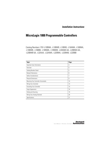
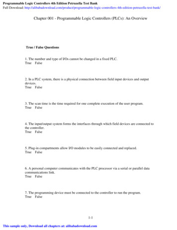
efesotomasyon.com - Allen Bradley,Rockwell,plc,servo,driveChapter1Hardware OverviewHardware FeaturesThe Bulletin 1762, MicroLogix 1200 programmable controller contains apower supply, input and output circuits, and a processor. The controller isavailable in 24 I/O and 40 I/O configurations.Figure 1.1 Hardware Features of the ControllerTop ViewSide View76108201512COM3947111Table 1.1 Hardware nal Blocks(Removable Terminal Blocks on 40-point controllersonly.)7Terminal Doors and Labels2Bus Connector Interface to Expansion I/O8Trim Pots3Input LEDs9Communications Toggle Push Button4Output LEDs10Memory Module Port Cover(1) -orMemory Module and/or Real-Time Clock(2)5Communication Port/Channel 011DIN Rail Latches6Status LEDs12Programmer/HMI Port(Equipped with 1762-LxxxxxR controllers only)(1) Shipped with controller.(2) Optional equipment.1Publication 1762-UM001F-EN-P - January 2010
efesotomasyon.com - Allen Bradley,Rockwell,plc,servo,drive1-2Hardware OverviewTable 1.2 Controller Input Power and Embedded I/OCatalog Number1762-L24AWA, 1762-L24AWAR1762-L24BWA, 1762-L24BWARDescriptionInput Power120/240V ac120/240V ac1762-L24BXB, 1762-L24BXBR24V dc1762-L40AWA, 1762-L40AWAR1762-L40BWA, 1762-L40BWAR120/240V ac120/240V ac1762-L40BXB, 1762-L40BXBR24V dcComponent DescriptionsInputs(14) 120V ac(10) 24V dc(4) fast 24V dc(10) 24V dc(4) fast 24V dc(24) 120V ac(20) 24V dc(4) fast 24V dc(20) 24V dc(4) fast 24V dcOutputs(10) relay(10) relay(5) relay, (4) 24V dc FET(1) high-speed 24V dc FET(16) relay(16) relay(8) relay, (7) 24V dc FET(1) high-speed 24V dc FETThese sections provide component descriptions for: MicroLogix 1200 Memory Module and/or Real-time Clock 1762 Expansion I/OMicroLogix 1200 Memory Module and/or Real-time ClockThe controller is shipped with a memory module port cover in place. You canorder a memory module, real-time clock, or memory module and real-timeclock as an accessory.Table 1.3 Memory Module and/or Real-time ClockPublication 1762-UM001F-EN-P - January 2010Catalog NumberDescription1762-MM1Memory Module only1762-RTCReal-time Clock only1762-MM1RTCMemory Module and Real-Time Clock
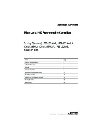
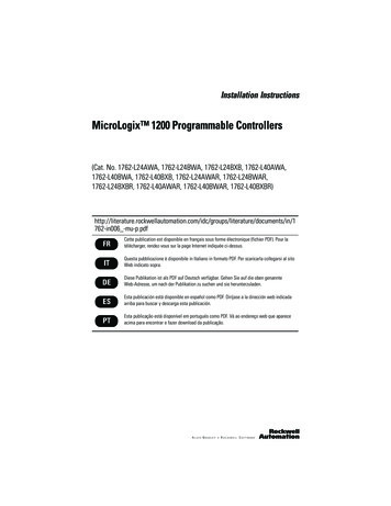
efesotomasyon.com - Allen Bradley,Rockwell,plc,servo,driveHardware Overview1-31762 Expansion I/O1762 expansion I/O can be connected to the MicroLogix 1200 controller, asshown below.1762 Expansion I/OTIP1762 Expansion I/O Connected to MicroLogix 1200 ControllerA maximum of six I/O modules, in certain combinations,may be connected to a controller. See Appendix F, SystemLoading and Heat Dissipation, to determine validcombinations.Table 1.4 Expansion I/OCatalog NumberDescriptions1762-IA88-point 120V ac Input1762-IQ88-point Sink/Source 24V dc Input1762-IQ1616-point Sink/Source 24V dc Input1762-IQ32T32-point Sink/Source 24V dc Input Module1762-OA88-point AC Triac Output1762-OB88-point Sourcing 24V dc Output1762-OB1616-point Sourcing 24V dc Output1762-OB32T32-point Sourcing 24V dc Output Module1762-OV32T32-point Sinking 24V dc Output Module1762-OW88-point AC/DC Relay Output1762-OW1616-point AC/DC Relay Output1762-OX6I6-point Isolated Relay Output1762-IF2OF22-channel Analog Voltage/Current Input2-channel Analog Voltage/Current Output1762-IF44-channel Analog Voltage/Current Input1762-OF44-channel Analog Voltage/Current Output1762-IR4RTD/Resistance Input1762-IT4Thermocouple/mV Input1762-IQ8OW6DC-input/Relay-output Combination ModulePublication 1762-UM001F-EN-P - January 2010
efesotomasyon.com - Allen Bradley,Rockwell,plc,servo,drive1-4Hardware OverviewCommunication CablesUse only the following communication cables with the MicroLogix 1200controllers. 1761-CBL-PM02 series C or later1761-CBL-HM02 series C or later1761-CBL-AM00 series C or later1761-CBL-AP00 series C or later2707-NC8 series A or later2702-NC9 series B or later2707-NC10 series B or later2707-NC11 series B or laterProgram the ControllerYou program the MicroLogix 1200 programmable controller using RSLogix500, revision 4 or later. You must use revision 4.5 or later of RSLogix 500 inorder to use the new features of the series B MicroLogix 1200 controllers,including the full ASCII instruction set. Communication cables forprogramming are not included with the software.Communication OptionsThe MicroLogix 1200 can be connected to a personal computer. It can also beconnected to a DH-485 network, or a Modbus network as an RTU Master orRTU Slave using an Advanced Interface Converter (catalog number1761-NET-AIC) and to the DeviceNet network using a DeviceNet Interface(catalog number 1761-NET-DNI). The controller can also be connected toDF1 Half-duplex networks as an RTU Master or RTU Slave. Series Bcontrollers may also be connected to serial devices using ASCII.See Chapter 4 Communication Connections for more information onconnecting to the available communication options.The 1762-LxxxxxR controllers provide an additional communication portcalled the Programmer/HMI Port. This port supports DF1 full-duplexprotocol only. The controller cannot initiate messages through this port. It canonly respond to messages sent to it. All communication parameters are fixedand cannot be changed by a user.See Default Communication Configuration on page 4-2 for the configurationsettings.Publication 1762-UM001F-EN-P - January 2010
efesotomasyon.com - Allen Bradley,Rockwell,plc,servo,driveChapter2Install Your ControllerThis chapter shows you how to install your controller.Topics include: Required ToolsAgency Certifications1required toolsagency certificationscompliance to European Union Directivesinstallation considerationssafety considerationspower considerationspreventing excessive heatmaster control relayinstall the memory module and/or real-time clockcontroller mounting dimensionscontroller and expansion I/O spacingmount the controllermount 1762 expansion I/Oconnect 1762 expansion I/OYou need a screwdriver and a drill. UL 508 C-UL under CSA C22.2 no. 142 Class I, Division 2, Groups A, B, C, D(UL 1604, C-UL under CSA C22.2 no. 213) CE compliant for all applicable directives C-Tick compliant for all applicable actsPublication 1762-UM001F-EN-P - January 2010
efesotomasyon.com - Allen Bradley,Rockwell,plc,servo,drive2-2Install Your ControllerCompliance to EuropeanUnion DirectivesThis product has the CE mark and is approved for installation within theEuropean Union and EEA regions. It has been designed and tested to meetthe following directives.EMC DirectiveThis product is tested to meet Council Directive 89/336/EECElectromagnetic Compatibility (EMC) and the following standards, in wholeor in part, documented in a technical construction file: EN 50081-2EMC - Generic Emission Standard, Part 2 - Industrial Environment EN 50082-2EMC - Generic Immunity Standard, Part 2 - Industrial EnvironmentThis product is intended for use in an industrial environment.Low Voltage DirectiveThis product is tested to meet Council Directive 73/23/EEC Low Voltage, byapplying the safety requirements of EN 61131-2 Programmable Controllers,Part 2 - Equipment Requirements and Tests.For specific information required by EN 61131-2, see the appropriate sectionsin this publication, as well as the following Allen-Bradley publications: Industrial Automation Wiring and Grounding Guidelines for NoiseImmunity, publication 1770-4.1 Guidelines for Handling Lithium Batteries, publication AG-5.4 Automation Systems Catalog, publication B113Installation ConsiderationsMost applications require installation in an industrial enclosure (PollutionDegree 2(1)) to reduce the effects of electrical interference (Over VoltageCategory II(2)) and environmental exposure. Locate your controller as far aspossible from power lines, load lines, and other sources of electrical noise suchas hard-contact switches, relays, and AC motor drives. For more informationon proper grounding guidelines, see the Industrial Automation Wiring andGrounding Guidelines publication 1770-4.1.(1) Pollution Degree 2 is an environment where normally only non-conductive pollution occurs except thatoccasionally temporary conductivity caused by condensation shall be expected.(2) Overvoltage Category II is the load level section of the electrical distribution system. At this level, transientvoltages are controlled and do not exceed the impulse voltage capability of the products insulation.Publication 1762-UM001F-EN-P - January 2010
efesotomasyon.com - Allen Bradley,Rockwell,plc,servo,driveInstall Your ControllerATTENTIONATTENTIONSafety Considerations2-3Vertical mounting of the controller is notrecommended due to heat build-up considerations.Be careful of metal chips when drilling mountingholes for your controller or other equipment withinthe enclosure or panel. Drilled fragments that fallinto the controller or I/O modules could causedamage. Do not drill holes above a mountedcontroller if the protective debris shields areremoved or the processor is installed.Safety considerations are an important element of proper system installation.Actively thinking about the safety of yourself and others, as well as thecondition of your equipment, is of primary importance. We recommendreviewing the following safety considerations.Hazardous Location ConsiderationsThis equipment is suitable for use in Class I, Division 2, Groups A, B, C, D ornon-hazardous locations only. The following WARNING statement applies touse in hazardous locations.WARNINGEXPLOSION HAZARD Substitution of components may impair suitabilityfor Class I, Division 2. Do not replace components or disconnecteq
efesotomasyon.com - Allen Bradley,Rockwell,plc,servo,drive. Publication 1762-UM001F-EN-P - January 2010 . Use this manual if you are responsible for designing, installing, programming, or troubleshooting control systems that use MicroLogix 1200 controllers. You should have a basic understanding of electrical circuitry and familiarity