Transcription
Installation InstructionsMicroLogix 1000 Programmable ControllersCatalog Numbers 1761-L10BWA, -L10BWB, -L10BXB, -L16AWA, -L16BWA,-L16BWB, -L16BBB, -L16NWA, -L16NWB, -L20AWA-5A, -L20BWA-5A,-L20BWB-5A, -L32AAA, -L32AWA, -L32BWA, -L32BWB, -L32BBBTopicPageImportant User Information4Overview5Catalog Number Detail5Related Publications6Safety Considerations7Physical Dimensions9Mounting Your Controller Horizontally10Wiring Your Controller13Grounding Your Controller15Surge Suppression16Sinking and Sourcing19Wiring Your Analog Channels20Specifications21
MicroLogix 1000 Programmable Controllers4Important User InformationBecause of the variety of uses for the products described in this publication, those responsiblefor the application and use of these products must satisfy themselves that all necessary stepshave been taken to assure that each application and use meets all performance and safetyrequirements, including any applicable laws, regulations, codes and standards. In no event willAllen-Bradley be responsible or liable for indirect or consequential damage resulting from theuse or application of these products.Any illustrations, charts, sample programs, and layout examples shown in this publication areintended solely for purposes of example. Since there are many variables and requirementsassociated with any particular installation, Allen-Bradley does not assume responsibility orliability (to include intellectual property liability) for actual use based upon the examplesshown in this publication.Allen-Bradley publication SGI-1.1, Safety Guidelines for the Application, Installation and Maintenanceof Solid-State Control (available from your local Allen-Bradley office), describes some importantdifferences between solid-state equipment and electromechanical devices that should be takeninto consideration when applying products such as those described in this publication.Reproduction of the contents of this copyrighted publication, in whole or part, withoutwritten permission of Rockwell Automation, is prohibited.Throughout this publication, notes may be used to make you aware of safety considerations.The following annotations and their accompanying statements help you to identify a potentialhazard, avoid a potential hazard, and recognize the consequences of a potential hazard:WARNING!ATTENTIONIdentifies information about practices or circumstances that can causean explosion in a hazardous environment, which may lead to personalinjury or death, property damage, or economic loss.Identifies information about practices or circumstances that can leadto personal injury or death, property damage, or economic loss.!IMPORTANTIdentifies information that is critical for successful application andunderstanding of the product.Publication 1761-IN001D-EN-P - June 2015
MicroLogix 1000 Programmable Controllers5OverviewInstall your controller using these installation instructions. The only tools you require are aFlat head or Phillips head screwdriver and drill.Catalog Number DetailThe catalog number for the controller is composed of the following:1761 - L 20 A W A - 5 AAnalog I/OBulletin NumberControllerNumber of Digital I/OInput Type:A 120V acB 24V dcN 24V ac or 24V dcNumber of Analog I/O:4 Inputs, 1 OutputPower SupplyA 120/240V acB 24V dcOutput Type:A TriacB 24V dc FETW RelayX Relay/24V dc FETPublication 1761-IN001D-EN-P - June 2015
MicroLogix 1000 Programmable Controllers6For More InformationRelated PublicationsForRefer to this DocumentPub. No.A description on how to use your MicroLogix 1000programmable controllers. This manual also containsstatus file data and instruction set information.MicroLogix 1000 ProgrammableControllers User Manual1761-6.3A procedural manual for technical personnel who use the MicroLogix 1000 with Hand-HeldProgrammer (HHP) User ManualAllen-Bradley Hand-Held Programmer (HHP) to monitorand develop control logic programs for the MicroLogix1000 controller.1761-6.2More information on proper wiring and groundingtechniques.1770-4.1Industrial Automation Wiring andGrounding GuidelinesThe procedures necessary to install and connect the AIC Advanced Interface Converterand DNI.(AIC ) and DeviceNet Interface(DNI) Installation Instructions1761-5.11A more detailed description on how to install and use your AIC Advanced Interface Converter 1761-6.4AIC Advanced Interface Converter.User ManualA more detailed description on how to install and use your DeviceNet Interface User ManualDeviceNet Interface.1761-6.5A more detailed description on how to install and use your Ethernet Interface User ManualEthernet Interface.1761-UM006If you would like a manual, you can: download a free electronic version from the internet:http://literature.rockwellautomation.com purchase a printed manual by contacting your local Allen-Bradley distributor orRockwell Automation representativePublication 1761-IN001D-EN-P - June 2015
MicroLogix 1000 Programmable Controllers7Safety ConsiderationsThis equipment is suitable for use in Class I, Division 2, Groups A, B, C, D or non-hazardouslocations only (when product or packing is marked).WARNING!Explosion Hazard: Substitution of components may impair suitability for Class I,Division 2. Do not replace components or disconnect equipment unlesspower has been switched off and the area is known to benon-hazardous. Do not connect or disconnect connectors while circuit is liveunless area is known to be non-hazardous. This product must be installed in an enclosure. All cablesconnected to the product must remain in the enclosure or beprotected by conduit or other means. The interior of the enclosure must be accessible only by the useof a tool. For applicable equipment (for example, relay modules), exposureto some chemicals may degrade the sealing properties of thematerials used in these devices:– Relays, epoxyIt is recommended that you periodically inspect these devices forany degradation of properties and replace the module ifdegradation is found.Use only the following communication cables in Class I, Division 2, Hazardous Locations.Environment ClassificationCommunication CableClass I, Division 2, Hazardous Environment1761-CBL-PM02 Series C1761-CBL-HM02 Series C1761-CBL-AM00 Series C1761-CBL-AP00 Series C1761-CBL-PH02 Series A1761-CBL-AH02 Series A2707-NC8 Series B2707-NC9 Series B2707-NC10 Series B2707-NC11 Series BPublication 1761-IN001D-EN-P - June 2015
MicroLogix 1000 Programmable Controllers8SécuritéCet équipement est conçu pour être utilisé dans des environnements de Classe 1, Division 2,Groupes A, B, C, D ou non dangereux (si indiqué sur le produit ou l'emballage).AVERTISSEMENT!Danger d'explosion : La substitution de composants peut rendre cet équipementimpropre à une utilisation en environnement de Classe 1,Division 2. Ne pas remplacer de composants ou déconnecter l'équipementsans s'être assuré que l'alimentation est coupée et quel'environnement est classé non dangereux. Ne pas connecter ou déconnecter les connecteurs lorsque lecircuit est alimenté, à moins que l'environnement ne soit classénon dangereux. Ce produit doit être installé dans un boîtier. Tous les câbles qui luisont connectés doivent rester dans le boîtier ou être protégés.N'utiliser que les câbles de communication suivants dans des environnements dangereux deClasse 1, Division 2.Classification d'environnementCâble de communicationEnvironnement dangereux Classe 1, Division 21761-CBL-PM02 Série C1761-CBL-HM02 Série C1761-CBL-AM00 Série C1761-CBL-AP00 Série C1761-CBL-PH02 Série A1761-CBL-AH02 Série A2707-NC8 Série B2707-NC9 Série B2707-NC10 Série B2707-NC11 Série BPublication 1761-IN001D-EN-P - June 2015
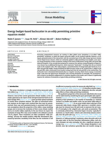
MicroLogix 1000 Programmable Controllers9Physical DimensionsController: 1761-Length: mm (in.)Depth: mm (in.)Height: mm (in.)L10BWA120 (4.72)73 (2.87)80 (3.15)L16BWAL16NWAL16AWA133 (5.24)L20AWA-5A200 (7.87)L20BWA-5AL32AWAL32BWAL32AAAL10BWB120 (4.72)40 (1.57)L10BXBL16BBBL16BWBL16NWBL20BWB-5A200 (7.87)L32BBBL32BWBController SpacingThe following figure shows the recommended minimum spacing for the controller.Top BSideSideAAA. Greater than or equal to 50.8 mm (2 in.)B. Greater than or equal to 50.8 mm (2 in.)Bottom BNote: The controller is shown horizontally mounted.Publication 1761-IN001D-EN-P - June 2015
MicroLogix 1000 Programmable Controllers10Mounting Your Controller HorizontallyThe controller should be mounted horizontally within an enclosure using either the DIN railor mounting screw option. Use the mounting template from the front of this document tohelp you space and mount the controller properly.ATTENTION!Be careful of metal chips when drilling mounting holes for yourcontroller. Drilled fragments that fall into the controller could causedamage. Do not drill holes above a mounted controller if theprotective wrap is removed.Using a DIN RailTo install your controller on the DIN rail:1. Mount your DIN rail. (Make sure that theplacement of the controller on the DIN railmeets the recommended spacingrequirements. Refer to the mounting templatefrom the back of this document.)ProtectiveWrapSide ViewMountingTemplateDIN Rail2. Hook the top slot over the DIN rail.3. While pressing the controller against the rail,snap the controller into position.4. Leave the protective wrap attached until youare finished wiring the controller.BADIN RailCCall-outDimensionA84 mm (3.3 in.)B33 mm (1.3 in.) maximumC16 mm (0.63 in.)Publication 1761-IN001D-EN-P - June 2015
MicroLogix 1000 Programmable Controllers11To remove your controller from the DIN rail:1. Place a screwdriver in the DIN rail latch at thebottom of the controller.Side View2. Holding the controller, pry downward on thelatch until the controller is released from theDIN rail.DIN RailUsing Mounting ScrewsTo install your controller using mountingscrews:MountingTemplate1. Remove the mounting template from theback of this document.2. Secure the template to the mountingsurface. (Make sure your controller isspaced properly.)3. Drill holes through the template.ProtectiveWrap4. Remove the mounting template.5. Mount the controller.6. Leave the protective wrap attached until you are finished wiring the controller.Mounting Your Controller VerticallyYour controller can also be mounted vertically within an enclosure using mounting screws ora DIN rail. To insure the stability of your controller, we recommend using mounting screws.For additional information, refer to the previous section.To insure the controller's reliability, the following environmental specifications must not beexceeded.Publication 1761-IN001D-EN-P - June 2015
MicroLogix 1000 Programmable ication:Operating Temperature0 C to 40 C ( 32 F to 113 F)(1)Operating Shock9.0g peak acceleration (11 1 ms duration)(Panel mounted)3 times each direction, each axisOperating Shock7.0g peak acceleration (11 1 ms duration)(DIN rail mounted)3 times each direction, each axis(1)12DC input voltage derated linearly from 30 C (30V to 26.4V).A. Greater than or equal to 50.8 mm (2 in.).Note: When mounting your controller vertically, the nameplate should be facing downward.Publication 1761-IN001D-EN-P - June 2015
MicroLogix 1000 Programmable Controllers13Wiring Your ControllerWire Type:Wire Size: (2 wire maximum per terminal screw)Solid#14 to #22 AWGStranded#16 to #22 AWGIMPORTANTThe diameter of the terminal screw head is 5.5 mm (0.220 in.). The inputand output terminals of the MicroLogix 1000 controller are designed forthe following spade lugs:WXLECCall-outDimensionC6.35 mm (0.250 in.)E10.95 mm (0.431 in.) maximumL14.63 mm (0.576 in.)W6.35 (0.250 in.)X3.56 mm (0.140 in.)C X9.91 mm (0.390 in.) maximumWe recommend using either of these AMP (or equal) spade lugs: part number 53120-1, ifusing 22-16 AWG, or part number 53123-1, if using 16-14 AWG.Publication 1761-IN001D-EN-P - June 2015
MicroLogix 1000 Programmable ControllersIMPORTANTIMPORTANT14If you use wires without lugs, make sure the wires are securely capturedby the pressure plate. This is particularly important at the four endterminal positions where the pressure plate does not touch the outsidewall of the controller.Be careful when stripping wires. Wire fragments that fall into thecontroller could cause damage. Remove the protective wrap after wiringyour controller. Failure to remove the wrap may cause the controller tooverheat.ProtectiveWrapIMPORTANTThis symbol denotes a functional earth ground terminal whichprovides a low impedance path between electrical circuits andearth for non-safety purposes, such as noise immunity improvement.Publication 1761-IN001D-EN-P - June 2015
MicroLogix 1000 Programmable Controllers15Grounding Your ControllerIn solid-state control systems, grounding helps limit the effects of noise due toelectromagnetic interference (EMI). Run the ground connection from the ground screw ofthe controller (third screw from left on output terminal rung) to the ground bus. Use theheaviest wire gauge listed for wiring your controller.Protective Wrap(remove after wiring)ATTENTION!All devices connected to the user 24V power supply or to the RS-232channel must be referenced to chassis ground or floating. Failure tofollow this procedure may result in property damage or personalinjury.Chassis ground, user 24V ground, and the RS-232 ground areinternally connected. You must connect the chassis ground terminalscrew to chassis ground prior to connecting any devices.On the 1761-L10BWB, -L10BXB, -L16BWB, -L16BBB, -L16NWB,-L20BWB-5A, -L32BBB, and -L32BWB controllers, the groundassociated with the user supplied 24V DC input power and chassisground are internally connected.You must also provide an acceptable grounding path for each device in your application. Formore information on proper grounding guidelines, see the Industrial Automation Wiring andGrounding Guidelines, (publication 1770-4.1).Publication 1761-IN001D-EN-P - June 2015
MicroLogix 1000 Programmable Controllers16Surge SuppressionInductive load devices such as motor starters and solenoids require the use of some type ofsurge suppression to protect the controller output contacts. Switching inductive loadswithout surge suppression can significantly reduce the life expectancy of relay contacts. Byadding a suppression device directly across the coil of inductive devices, you prolong the lifeof the output circuits. You also reduce the effects of radiated voltage transients and preventelectrical noise from radiating into system wiring and facility.The following diagram shows an output with a suppression device. We recommend that youlocate the suppression device as close as possible to the load device. dc or L1VAC/DCSuppression DeviceOut 0Out 1ac or dcOutputsOut 2Out 3Out 4Out 5Out 6Out 7COMdc COM or L2If you connect a micro controller FET output to an inductive load, we recommend that youuse an 1N4004 diode for surge suppression, as shown in the illustration on page 17.Publication 1761-IN001D-EN-P - June 2015
MicroLogix 1000 Programmable Controllers17Suitable surge suppression methods for inductive load devices include a varistor, an RCnetwork, or, for dc loads, a diode. These components must be appropriately rated to suppressthe switching transient characteristic of the particular inductive device. See the table onpage 18 for recommended suppressors.As the following diagram illustrates, these surge suppression circuits connect directly acrossthe load device. This reduces arcing and damage of the output contacts. (High transients cancause arcing that occurs when switching off an inductive device.)Surge Suppression for Inductive ac Load DevicesOutput DeviceOutput DeviceVaristorRC NetworkOutput DeviceDiode (A surge suppressorcan also be used.)If you connect a micro controller triac output to control an inductive load, we recommendthat you use varistors to suppress noise. Choose a varistor that is appropriate for theapplication. The suppressors we recommend for triac outputs when switching 120V acinductive loads are a Harris MOV, part number V175 LA10A, or an Allen-Bradley MOV,catalog number 599-K04 or 599-KA04. Consult the varistor manufacturer's data sheet whenselecting a varistor for your application.For inductive dc load devices, a diode is suitable. A 1N4004 diode is acceptable for mostapplications. A surge suppressor can also be used. See the table on page 18 forrecommended suppressors.Publication 1761-IN001D-EN-P - June 2015
MicroLogix 1000 Programmable Controllers18Recommended Surge SuppressorsWe recommend the Allen-Bradley surge suppressors shown in the following table for usewith Allen-Bradley relays, contactors, and starters.DeviceCoil VoltageSuppressor CatalogNumberBulletin 509 Motor StarterBulletin 509 Motor Starter120V ac240V ac599-K04(1)Bulletin 100 ContactorBulletin 100 Contactor120V ac240V ac199-FSMA1(2)599-KA04(1)199-FSMA2(2)Bulletin 709 Motor Starter120V ac1401-N10Bulletin 700 Type R, RM Relaysac coilNone RequiredBulletin 700 Type R RelayBulletin 700 Type RM Relay12V dc12V dc199-FSMA9Bulletin 700 Type R RelayBulletin 700 Type RM Relay24V dc24V dc199-FSMA9Bulletin 700 Type R RelayBulletin 700 Type RM Relay48V dc48V dc199-FSMA9Bulletin 700 Type R RelayBulletin 700 Type RM Relay115-125V dc115-125V dc199-FSMA10Bulletin 700 Type R RelayBulletin 700 Type RM Relay230-250V dc230-250V dc199-FSMA11Bulletin 700 Type N, P, or PK Relay150V max, ac or DC700-N24(2)Miscellaneous electromagnetic devices limited to35 sealed VA150V max, ac or DC700-N24(2)(1)Varistor – Not recommended for use on relay outputs.(2)RC Type – Do not use with triac outputs.Publication 1761-IN001D-EN-P - June 2015
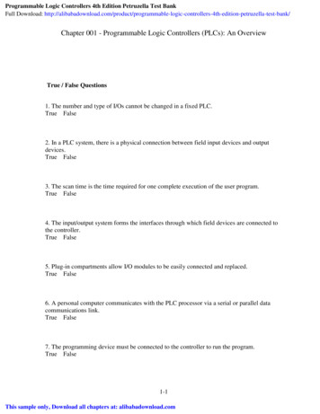
MicroLogix 1000 Programmable Controllers19Sinking and SourcingAny MicroLogix 1000 DC input can be configured as sinking or sourcing depending on howthe DC COM terminal is wired.Mode:Definition:SinkingThe input energizes when high-level voltage is applied to the input terminal (activehigh). Connect the power supply VDC (-) to the corresponding DC COM terminal.SourcingThe input energizes when low-level voltage is applied to the input terminal (active low).Connect the power supply VDC ( ) to the corresponding DC COM terminal.Sinking and Sourcing Wiring ExamplesFigure 1 1761-L32BWASourcing InputsSinking Inputs14-30 VDCVDC ( ) for SourcingVDC (-) for SourcingVDC ( ) for SinkingVDC (-)for Sinking 24V DC OUTDCCOMI/0I/1I/2I/3DCCOMI/4I/5I/6I/7I/8Sourcing InputsI/9I/10I/11I/12I/13I/14I/15 I/16I/17I/18I/19Sinking Inputs14-30 VDCVDC ( )VDC (-) for SinkingVDC ( )for SinkingVDC (-) for Sourcingfor Sourcing 24V DC 1I/12I/13I/14I/15 I/16I/17I/18I/19Publication 1761-IN001D-EN-P - June 2015
MicroLogix 1000 Programmable Controllers20Wiring Your Analog ChannelsAnalog input circuits can monitor current and voltage signals and convert them to serialdigital data. The analog output can support either a voltage or a current function as shown inthe following illustration.Sensor 2(V) VoltageSensor 3(I) CurrentSensor 1(V) 5IA/0V ( )O/6IA/1V ( )IA(-)IASHDIA/2I ( )IA/3I ( )IA(-)NOTOASHDOA/0V ( )OA/0I ( )OA(-)O/7 USEDYou can configure either voltage orcurrent output operation.Sensor 4(I) Current- or meterThe controller does not provide loop power for analog inputs. Use a power supply thatmatches the transmitter specifications as shown below.2-Wire TransmitterPowerSupply -3-Wire TransmitterPowerSupply -TransmitterSupplySignalGND -ControllerIA/0 - 3 ( )IA (-)Controller -4-Wire TransmitterPowerSupplyTransmitterIA/0 - 3 ( )IA (-)TransmitterSupplySignal - -ControllerIA/0 - 3 ( )IA (-)Publication 1761-IN001D-EN-P - June 2015
MicroLogix 1000 Programmable Controllers21Minimizing Electrical Noise on Analog ControllersInputs on analog controllers employ digital high-frequency filters that significantly reduce theeffects of electrical noise on input signals. However, because of the variety of applications andenvironments where analog controllers are installed and operated, it is impossible to ensurethat all environmental noise will be removed by the input filters.Several specific steps can be taken to help reduce the effects of environmental noise onanalog signals: install the MicroLogix 1000 system in a properly rated (i.e., NEMA) enclosure. Makesure that the MicroLogix 1000 system is properly grounded. use Belden cable #8761 for wiring the analog channels, making sure that the drainwire and foil shield are properly earth grounded. route the Belden cable separate from any ac wiring. Additional noise immunity can beobtained by routing the cables in grounded conduit.Grounding Your Analog CableUse shielded communicationcable (Belden #8761). The Beldencable has two signal wires (blackand clear), one drain wire, and afoil shield. The drain wire and foilshield must be grounded at oneend of the cable. Do not groundthe drain wire and foil shield atboth ends of the cable.Foil ShieldBlack WireInsulationDrain WireClear WireSpecificationsEnvironmental Specifications (all MicroLogix controllers)DescriptionSpecificationOperating Temperature0 C to 55 C ( 32 F to 131 F) for horizontal mounting0 C to 40 C ( 32 F to 104 F) for vertical mounting(1)Publication 1761-IN001D-EN-P - June 2015
MicroLogix 1000 Programmable ControllersDescriptionSpecificationStorage Temperature-40 C to 85 C (-40 F to 185 F)Operating Humidity5 to 95% non-condensingAgency Certification (whenproduct or packaging ismarked) C-UL Class I, Division 2 Groups A,B,C,D certified(1)22 UL listed (Class I, Division 2 Groups A,B,C,D certified) CE/RCM/EAC compliant for all applicable directivesDC input voltage derated linearly from 30 C (30V to 26.4V).General SpecificationsDescription:Specification: 1761-L16AWA 32AWA 10BWA 16BWA 32BWA 32AAA 10BXB 10BWB 32BWB16NWA16BBB 16BWB 32BBB16NWBMemory Size andType1 K EEPROM (approximately 737 instruction words: 437 data words)Power SupplyVoltage85-264V ac, 47-63 HzPowerSupplyUsage20.4-26.4V dc120V ac15 VA19 VA24 VA26 VA29 VA16 VA240V ac21 VA25 VA32 VA33 VA36 VA22 VA24V dcPower Supply MaxInrush CurrentNot ApplicableNot Applicable5W30A for 8 ms30A for 4 ms24V dc Sensor Power Not Applicable(V dc at mA)200 mAMax Capacitive Load(User 24V dc)200 µF7WNot ApplicablePower Cycles50,000 minimumVibrationOperating: 5 Hz to 2k Hz, 0.381 mm (0.015 in.) peak to peak/2.5g panel mounted,(1) 1hrper axisNon-operating: 5 Hz to 2k Hz, 0.762 mm (0.030 in.) peak to peak/5g, 1hr per axisShock(2)Operating: 10g peak acceleration (7.5g DIN rail mounted)(3) (11 1 ms duration) 3 timeseach direction, each axisNon-operating: 20g peak acceleration (11 1 ms duration), 3 times each direction, eachaxisTerminal ScrewTorque0.9 N-m maximum (8.0 in.-lbs)ElectrostaticDischargeEN 61000-2 at 8K VPublication 1761-IN001D-EN-P - June 2015
MicroLogix 1000 Programmable ControllersDescription:23Specification: 1761-L16AWA 32AWA 10BWA 16BWA 32BWA 32AAA 10BXB 10BWB 32BWB16NWA16BBB 16BWB 32BBB16NWBRadiatedSusceptibilityEN 61000-3 at 10 V/m, 27 MHz - 1000 MHz; 3V/m, 87 MHz - 108 MHz, 174 MHz - 230MHz, and 470 MHz - 790 MHzFast TransientEN 61000-4 at 2K V Power Supply, I/O; 1K V CommsIsolation1500V ac(1)DIN rail mounted controller is 1g.(2)Refer to page 12 for vertical mounting specifications.(3)Relays are derated an additional 2.5g on 32 pt. controllers.Analog General SpecificationsDescription:Specification: 1761-L20AWA-5A20BWA-5A20BWB-5AMemory Size and Type 1 K EEPROM (approximately 737 instruction words: 437 data words)Power Supply VoltagePowerSupplyUsage85-264V ac, 47-63 Hz20.4-26.4V dc120V ac 20 VA30 VA240V ac 27 VA38 VA24V dcNot ApplicableNot Applicable10W24V dc Sensor Power (V Not Applicabledc at mA)200 mAMax Capacitive Load(User 24V dc)200 µFNot ApplicablePower Cycles50,000 minimumVibrationOperating: 5 Hz to 2k Hz, 0.381 mm (0.015 in.) peak to peak/2.5g panel mounted,(1) 1hrper axisNon-operating: 5 Hz to 2k Hz, 0.762 mm (0.030 in.) peak to peak/5g, 1hr per axisShock(2)Operating: 10g peak acceleration (7.5g DIN rail mounted)(3) (11 1 ms duration) 3 timeseach direction, each axisNon-operating: 20g peak acceleration (11 1 ms duration), 3 times each direction,each axisTerminal Screw Torque 0.9 N-m maximum (8.0 in.-lbs)Electrostatic Discharge EN 61000-2 at 8K V Discrete I/O4K V Contact, 8K V Air for Analog I/ORadiated Susceptibility EN 61000-3 at 10 V/m, 27 MHz - 1000 MHz3 V/m, 87 MHz - 108 MHz, 174 MHz - 230 MHz, and 470 MHz - 790 MHzFast TransientEN 61000-4 at 2K V Power Supply, I/O; 1K V CommsIsolation1500V ac(1)DIN rail mounted controller is 1g.(2)Refer to page 12 for vertical mounting specifications.Publication 1761-IN001D-EN-P - June 2015
MicroLogix 1000 Programmable Controllers(3)24Relays are derated an additional 2.5g on 20 pt. controllers.General Input SpecificationsDescriptionSpecification100-120V ac Controllers24V dc ControllersVoltage Range79 to 132V ac, 47 to 63 Hz14 to 30V dcOn Voltage79V ac min.132V ac max.14V dc min.24V dc nominal26.4V dc max. at 55 C ( 131 F)30.0V dc max. at 30 C ( 86 F)Off Voltage20V ac5V dcOn Current5.0 mA min. at 79V ac 47 Hz12.0 mA nominal at 120V ac 60 Hz16.0 mA max. at 132V ac 63 Hz2.5 mA min. at 14V dc8.0 mA nominal at 24V dc12.0 mA max. at 30V dcOff Current2.5 mA max.1.5 mA max.Nominal Impedance12K ohms at 50 Hz10K ohms at 60 Hz3K ohmsInrush Maximum250 mA max.(1)Not Applicable(1)To reduce the inrush maximum to 35 mA, apply a 6.8K ohm, 5W resistor in series with the input. The on-state voltageincreases to 92V ac as a resultAC/DC Input Specifications for 1761-L16NWA and 1761-L16NWBSpecification(1)On State VoltageOn State CurrentOff State VoltageAC Excitation(2)DC Excitation14V dcMinimum18V acNominal24V ac24V dcMaximum26.4V ac at 55 C (131 F)30V ac at 30 C (86 F)26.4V dc at 55 C (131 F)30V dc at 30 C (86 F)2.5 mA at 14V dcMinimum3.0 mA at 18V acNominal8.0 mA at 24V ac8.0 mA at 24V dcMaximum12 mA at 30V ac12 mA at 30V dcMinimum0.0V ac0.0V dcMaximum3.0V ac5.0V dcOff State CurrentMinimum1.0 mA1.5 mAFrequencyNominal50/60 Hzsee Turn On Time/Turn Off TimeRange47 to 63 HzPublication 1761-IN001D-EN-P - June 2015
MicroLogix 1000 Programmable ControllersAC Excitation(2)Specification(1)Turn On Time(3)Turn Off Time(3)DC ExcitationMinimum2 ms2 msMaximum20 ms20 msMinimum10 ms10 msMaximum20 ms20 ms(1)Input circuits may be operated ac or dc on a group basis only.(2)All ac specifications are sinusoidal RMS values.(3)Turn On and Turn Off Times are not adjustable.25Analog Input SpecificationsDescriptionSpecificationVoltage Input Range-10.5 to 10.5V dc - 1LSBCurrent Input Range-21 to 21 mA - 1LSBType of Data16-bit signed integerInput Coding -21 to 21 mA - 1LSB, -10.5 to 10.5V dc - 1 LSB-32,768 to 32,767Voltage Input Impedance210K ΩCurrent Input Impedance160ΩInput Resolution(1)16 bitNon-linearity0.002%Overall Accuracy 0 C to 55 C .0.7% of full scaleOverall Accuracy Drift 0 C to 55 C (max.) 0.176%Overall Error at 25 C ( 77 F) (max.) 0.525%Voltage Input Overvoltage Protection24V dcCurrent Input Overcurrent Protection 50 mAInput to Output Isolation30V rated working/500V isolationField Wiring to Logic Isolation(1)The analog input update rate and input resolution are a function of the input filter selection.Analog Input Update RatesProgrammable Filter Characteristics1st Notch Freq (Hz) Filter BandwidthUpdate TimeSettling Time(mSec)(1)(mSec)(1)100.00400.00(Bits)(-3 dB Freq Hz)102.62Resolution16Publication 1761-IN001D-EN-P - June 2015
MicroLogix 1000 Programmable Controllers26Programmable Filter Characteristics1st Notch Freq (Hz) Filter BandwidthUpdate TimeSettling Time(mSec)(1)(mSec)(1)(-3 dB Freq .6766.671625065.504.0016.0015(1)The total update time for each channel is a combination of the Update Time and the Settling Time. When more than oneanalog input channel is enabled, the maximum update for each channel is equal to one ladder scan time plus the channel'sUpdate Time plus Settling Time. When only one analog input channel is enabled, the maximum update for the channel isequal to the Update Time plus one ladder scan time for all except the first update after Going to Run (GTR). The first updatetime is increased by the Settling Time.(2)60 Hz is the default setting.General Output SpecificationsTypeRelayVoltageSee Wiring Diagrams, p. 121.MOSFETMax Load CurrentSee RelayContactRatings onpage 27.1.0A per point at 55 C ( 131 F) 0.5A per point at 55 C (131 F)Min Load Current10.0 mA1 mA10.0 mACurrent per Controller1440 VA3A for L16BBB6A for L32BBB1440 VACurrent per Common8.0A3A for L16BBB6A for L32BBBNot ApplicableMax Off State Leakage 0 mACurrent1 mA2 mA at 132V ac4.5 mA at 264V acOff to On Response10 ms max.0.1 ms8.8 ms at 60 Hz10.6 ms at 50 HzOn to Off Response10 ms max.1 ms11.0 ms1.5A per point at 30 C ( 86 F) 1.0A per point at 30 C (86 F)Surge Current per Point Not Applicable 4A for 10 ms(1)Relay life- ElectricalRefer to Relay –Life ChartbelowRelay lilfe - Mechanical 20,000,000cycles(1)Triac–10A for 25 ms(1)––Repeatability is once every 2 seconds at 55 C ( 131 F).Publication 1761-IN001D-EN-P - June 2015
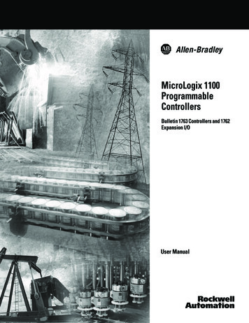
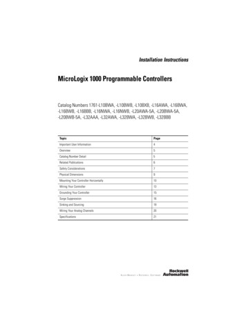
MicroLogix 1000 Programmable Controllers27Relay Contact Rating amperesMakeMakeBreak240V ac7.5A0.75A2.5A1800 VA180 VA120V ac15A1.5A125V dc0.22A(1)1.0A28 VA24V dc(1)1.2A2.0A(1)For dc voltage applications, the make/break ampere rating for relay contacts can be determined by dividing 28 VA by theapplied dc voltage. For example, 28 VA 48V dc 0.58A. For dc voltage applications less than 48V, the make/break ratingsfor relay contacts cannot exceed 2A. For dc voltage applications greater than 48V, the make/break ratings for relay contactscannot exceed 1A.Do not exceed the “Current per common” specification.ATTENTION!Relay Life ChartNumber of operations (x 104)500300100250-VAC/30-VDC resistive load5030105 250-VAC/30 VDC inductive load(cosφ 0.4/ L/R 7 ms)3012345678910Switching capacity(A)Publication 1761-IN001D-EN-P - June 2015
MicroLogix 1000 Programmable Controllers2
Controllers User Manual 1761-6.3 A procedural manual for technical personnel who use the Allen-Bradley Hand-Held Programmer (HHP) to monitor and develop control logic programs for the MicroLogix 1000 controller. MicroLogix 1000 with Hand-Held Programmer (HHP) User Manual 1761-6.2 More information on proper wiring and grounding techniques.