Transcription
Installation InstructionsMicro800 Remote LCDCatalog Number eFRITDEESCette publication est disponible en françaissous forme électronique (fichier PDF). Pour latélécharger, rendez-vous sur la page Internetindiquée ci-dessus.Questa pubblicazione è disponibile inItaliano in formato PDF. Per scaricarlacollegarsi al sito Web indicato sopra.Diese Publikation ist als PDF auf Deutschverfügbar. Gehen Sie auf die oben genannteWeb-Adresse, um nach der Publikation zusuchen und sie herunterzuladen.ZHEsta publicación está disponible en españolcomo PDF. Diríjase a la dirección webindicada arriba para buscar y descarga estapublicación.KOPTEsta publicação está disponível em portuguéscomo PDF. Vá ao endereço web que apareceacima para encontrar e fazer download dapublicação.ZCTable of ContentsTopicPageImportant User Information2North American Hazardous Location Approval4Additional Resources6Overview7Additional Resources6Install the Micro800 Remote LCD9Mount the Module10RS232 Port16USB Port16Connect Power14Specifications18
2Micro800 Remote LCDImportant User InformationSolid state equipment has operational characteristics differing from those of electromechanical equipment. Safety Guidelinesfor the Application, Installation and Maintenance of Solid State Controls (Publication SGI-1.1 available from your local RockwellAutomation sales office or online at http://rockwellautomation.com/literature) describes some important differences betweensolid state equipment and hard-wired electromechanical devices. Because of this difference, and also because of the widevariety of uses for solid state equipment, all persons responsible for applying this equipment must satisfy themselves that eachintended application of this equipment is acceptable.In no event will Rockwell Automation, Inc. be responsible or liable for indirect or consequential damages resulting from the useor application of this equipment.The examples and diagrams in this manual are included solely for illustrative purposes. Because of the many variables andrequirements associated with any particular installation, Rockwell Automation, Inc. cannot assume responsibility or liability foractual use based on the examples and diagrams.No patent liability is assumed by Rockwell Automation, Inc. with respect to use of information, circuits, equipment, or softwaredescribed in this manual.Reproduction of the contents of this manual, in whole or in part, without written permission of Rockwell Automation, Inc., isprohibited.Throughout this manual, when necessary, we use notes to make you aware of safety considerations.WARNING: Identifies information about practices or circumstances that can cause an explosion in ahazardous environment, which may lead to personal injury or death, property damage, or economic loss.ATTENTION: Identifies information about practices or circumstances that can lead to personal injury ordeath, property damage, or economic loss. Attentions help you identify a hazard, avoid a hazard andrecognize the consequences.SHOCK HAZARD: Labels may be on or inside the equipment (for example, drive or motor) to alert peoplethat dangerous voltage may be present.BURN HAZARD: Labels may be on or inside the equipment (for example, drive or motor) to alert peoplethat surfaces may reach dangerous temperatures.IMPORTANT IMPORTANT: Identifies information that is critical for successful application and understanding of theproduct.Rockwell Automation Publication 2080-IN010B-EN-P – May 2015
Micro800 Remote LCD3Environment and EnclosureATTENTION: This equipment is intended for use in a Pollution Degree 2industrial environment, in overvoltage Category II applications (as defined in IEC60664-1), at altitudes up to 2000 m (6562 ft) without derating.This equipment is not intended for use in residential environments and may notprovide adequate protection to radio communication services in suchenvironments.This equipment is supplied as open-type equipment. It must be mounted withinan enclosure that is suitably designed for those specific environmentalconditions that will be present and appropriately designed to prevent personalinjury resulting from accessibility to live parts. The enclosure must have suitableflame-retardant properties to prevent or minimize the spread of flame,complying with a flame spread rating of 5VA or be approved for the application ifnonmetallic. The interior of the enclosure must be accessible only by the use ofa tool. Subsequent sections of this publication may contain additionalinformation regarding specific enclosure type ratings that are required to complywith certain product safety certifications.In addition to this publication, see: Industrial Automation Wiring and Grounding Guidelines, RockwellAutomation publication 1770-4.1, for additional installation requirements. NEMA Standard 250 and IEC 60529, as applicable, for explanations of thedegrees of protection provided by different types of enclosure.Prevent Electrostatic DischargeATTENTION: This equipment is sensitive to electrostatic discharge, which cancause internal damage and affect normal operation. Follow these guidelineswhen you handle this equipment: Touch a grounded object to discharge potential static.Wear an approved grounding wriststrap.Do not touch connectors or pins on component boards.Do not touch circuit components inside the equipment.Use a static-safe workstation, if available.Store the equipment in appropriate static-safe packaging when not in use.Rockwell Automation Publication 2080-IN010B-EN-P – May 2015
4Micro800 Remote LCDNorth American Hazardous Location ApprovalThe following modules are North American Hazardous Location approved: 2080-REMLCD.The following information applies whenoperating this equipment in hazardouslocations:Informations sur l’utilisation de cetéquipement en environnementsdangereux:Products marked "CL I, DIV 2, GP A, B, C, D" aresuitable for use in Class I Division 2 Groups A, B,C, D, Hazardous Locations and nonhazardouslocations only. Each product is supplied withmarkings on the rating nameplate indicating thehazardous location temperature code. Whencombining products within a system, the mostadverse temperature code (lowest "T" number)may be used to help determine the overalltemperature code of the system. Combinationsof equipment in your system are subject toinvestigation by the local Authority HavingJurisdiction at the time of installation.Les produits marqués "CL I, DIV 2, GP A, B, C,D" ne conviennent qu'à une utilisation enenvironnements de Classe I Division 2 GroupesA, B, C, D dangereux et non dangereux.Chaque produit est livré avec des marquagessur sa plaque d'identification qui indiquent lecode de température pour les environnementsdangereux. Lorsque plusieurs produits sontcombinés dans un système, le code detempérature le plus défavorable (code detempérature le plus faible) peut être utilisépour déterminer le code de température globaldu système. Les combinaisons d'équipementsdans le système sont sujettes à inspection parles autorités locales qualifiées au moment del'installation.WARNING: EXPLOSIONHAZARDWARNING: RISQUED’EXPLOSION Do not disconnect equipmentunless power has been removed orthe area is known to benonhazardous. Couper le courant ou s'assurerque l'environnement est classénon dangereux avant dedébrancher l'équipement. Do not disconnect connections tothis equipment unless power hasbeen removed or the area is knownto be nonhazardous. Secure anyexternal connections that mate tothis equipment by using screws,sliding latches, threadedconnectors, or other meansprovided with this product. Couper le courant ou s'assurerque l'environnement est classénon dangereux avant dedébrancher les connecteurs. Fixertous les connecteurs externesreliés à cet équipement à l'aidede vis, loquets coulissants,connecteurs filetés ou autresmoyens fournis avec ce produit. Substitution of any component mayimpair suitability for Class I,Division 2. La substitution de tout composantpeut rendre cet équipementinadapté à une utilisation enenvironnement de Classe I,Division 2. If this product contains batteries,they must only be changed in anarea known to be nonhazardous. S'assurer que l'environnement estclassé non dangereux avant dechanger les piles.Rockwell Automation Publication 2080-IN010B-EN-P – May 2015
Micro800 Remote LCD5 Make sure all connectors are securely tightened to properly seal theconnections against leaks and maintain IP enclosure type requirements. The USB port is intended for temporary local programming purposes only andnot intended for permanent connection. The USB cable is not to exceed 3.0 m (9.84 ft) and must not contain hubs. The RS232 and Power cables are not to exceed 3.0 m (9.84 ft). Do not place the module in direct sunlight. Prolonged exposure to sunlight maydegrade the LCD. The USB cap must be in place to maintain IP65 rating. If you connect or disconnect the RS232 cable with power applied to this moduleor the serial device on the other end of the cable, an electrical arc can occur.This could cause an explosion in hazardous location installations.Be sure that power is removed or the area is nonhazardous before proceeding. If you connect or disconnect the communications cable with power applied tothis module or any device on the network, an electrical arc can occur. This couldcause an explosion in hazardous location installations.Be sure that power is removed or the area is nonhazardous before proceeding. When used in a Class I, Division 2, hazardous location, this equipment must bemounted in a suitable enclosure with proper wiring method that complies withthe governing electrical codes. The USB port is intended for temporary local programming purposes only andnot intended for permanent connection. If you connect or disconnect the USBcable with power applied to this module or any device on the USB network, anelectrical arc can occur. This could cause an explosion in hazardous locationinstallations.Be sure that power is removed or the area is nonhazardous before proceeding. Do not connect directly to line voltage. Line voltage must be supplied by asuitable, approved isolating transformer or power supply having short circuitcapacity not exceeding 100V A maximum or equivalent. Do not use the USB port in hazardous locations.Rockwell Automation Publication 2080-IN010B-EN-P – May 2015
6Micro800 Remote LCDAdditional ResourcesResourceDescriptionMicro820 20-point ProgrammableControllers User Manual, publication2080-UM005Micro800 Plug-in Modules and AccessoriesUser Manual, publication 2080-UM004Micro820 Programmable ControllersInstallation Instructions, publication2080-IN009Micro800 AC Power Supply InstallationInstructions, publication 2080-IN001Industrial Automation Wiring andGrounding Guidelines, publication 1770-4.1A more detailed description of how to install and use yourMicro820 programmable controller.Installation and wiring descriptions for the different Micro800plug-in modules and accessories.Information on how to install your Micro820programmable controller.Information on wiring and installing the optional AC power supply.More information on proper wiring and grounding techniques.If you would like a manual, you can: download a free electronic version from the Internet:http://rockwellautomation.com/literature purchase a printed manual by contacting your local Allen-Bradley distributor orRockwell Automation representativeRockwell Automation Publication 2080-IN010B-EN-P – May 2015
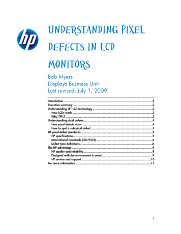
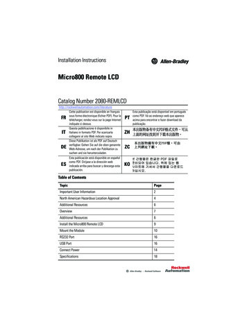
Micro800 Remote LCD7OverviewThe Micro800 Remote LCD is a simple IP65 text display interface that allows configuration ofsuch settings as IP address on the Micro800 controller. It is an accessory to the Micro820controller.The remote LCD can be connected to the controller through an RS232 port. It can be mountedthrough the front panel or on the same DIN rail as the controller.Micro800 Remote LCD 80-REMLCD DescriptionDescriptionDescription(1)1Logo casing6DIN rail latch2Display screen7USB port3Function keys8RS232 port4Arrow keys924V DC power port5ESC and OK keys(1)The module is shipped with the Allen-Bradley sticker label but you can customize the space with yourproduct logo. Dimensions for the logo casing and the sticker label are shown below.37136.704.705Sticker casingSticker labelMeasurements are in millimeters.Rockwell Automation Publication 2080-IN010B-EN-P – May 2015
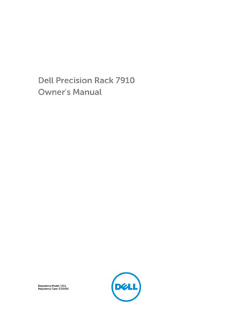
8Micro800 Remote LCDATTENTION: The length of RS232 and 24V DC power cable connectionto the 2080-REMLCD module must not exceed 3 m (9.84 F4F2F3ESCF5F6OKMENU46258RS232 and 24V DC power cableconnections must not exceed 3 m.Module DimensionsbcaF1F2F3ESCF4F5F6OKMENUCatalog NumberHeight (a)Width (b)Depth (c)2080-REMLCD97 mm (3.82 in.)130 (5.11 in.)35.5 (1.40 in.)Rockwell Automation Publication 2080-IN010B-EN-P – May 2015
Micro800 Remote LCD9Parts ListThe Micro800 Remote LCD module ships with these items: Allen-Bradley sticker label Clamp accessories for panel mounting (4 pcs) Product Information (publication 2080-PC002)Install the Micro800 Remote LCDBefore installing the Remote LCD through the front panel, review minimum clearances, panelguidelines, panel cutout dimensions, and product dimensions.IMPORTANTMost applications require installation in an industrial enclosure toreduce the effects of electrical interference and environmentalexposure. Locate your device as far as possible from power lines, loadlines, and other sources of electrical noise such as hard-contactswitches, relays, and AC motor drives. For more information on propergrounding guidelines, see the Industrial Automation Wiring andGrounding Guidelines, publication 1770-4.1.Minimum SpacingMaintain spacing from objects such as enclosure walls, wireways, and adjacent equipment. Allow50.8 mm (2.0 in.) of space on all sides for adequate ventilation. If optional accessories/modulesare attached such as the optional power supply, 2080-PS120-240VAC, make sure that there is50.8 mm (2.0 in.) of space on all sides after attaching the optional parts.Plan for adequate space around the module, inside the enclosure, for ventilation and cabling.Consider heat produced by other devices in the enclosure. The ambient temperature around themodule must be -20 50 C (-4 122 F).TIPThe minimum spacing requirements are sufficient for connecting cables and inserting.Plan for additional clearance if using the USB host port on the back of the unit.Panel GuidelinesSupporting panels must be at least 16 gauge to provide proper sealing against water and dust andto provide proper support. The panel surface must be flat and free of imperfections to maintainan adequate seal and NEMA/IP Type ratings.Rockwell Automation Publication 2080-IN010B-EN-P – May 2015
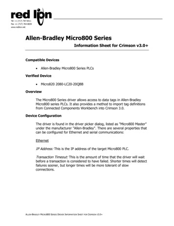
10Micro800 Remote LCDPanel Cutout DimensionsYou can print the panel cutout template that comes at the end of this installation instructions.Panel cutout dimensions are provided in the next table.Catalog NumberHeight, Approx., mm (inches)Width, Approx., mm (inches)2080-REMLCD88.5 0.5 (3.48 0.02)121.5 0.5 (4.78 0.02)ATTENTION: Disconnect all electrical power from the panel beforemaking the panel cutout. Make sure the area around the panel cutout is clear. Take precautions so metal cuttings do not enter any componentsalready installed in the panel. Failure to follow these instructions may result in personal injury ordamage to panel components.WARNING: If you connect or disconnect the RS232 cable with powerapplied to this module or the RS232 device on the other end of thecable, an electrical arc can occur. This could cause an explosion inhazardous location installations.Be sure that power is removed or the area is nonhazardous beforeproceeding.WARNING: When used in a Class I, Division 2, hazardous location, thisequipment must be mounted in a suitable enclosure with proper wiringmethod that complies with the governing electrical codes.Mount the ModuleThere are two ways to mount the Micro800 Remote LCD, as described in the following sections: Mount the Module in a Panel Mount the Module on a DIN RailRockwell Automation Publication 2080-IN010B-EN-P – May 2015
Micro800 Remote LCD11Mount the Module in a PanelThe Micro800 Remote LCD installs easily on the front panel. Use the clamp accessories shippedwith your module to mount it.130 (5.11)120.7 (4.75)130(3.81)87.7(3.45)Measurements are in millimeters (inches)Panel thickness: 1 535 (max)mountingscrewclampsNOTE: The REMLCD module can onlybe installed through the front panel.PanelgasketRockwell Automation Publication 2080-IN010B-EN-P – May 2015
12Micro800 Remote LCDFollow these steps to mount the remote LCD through the front panel.1. Make sure the sealing gasket is properly positioned on the module.This gasket forms a compression type seal. Do not use sealing compounds.2. Place the module in the panel cutout.IMPORTANTThe module temperature must be greater than 0 C (32 F) during panelinstallation.The module is shipped with the Allen-Bradley logosticker (36.70 x 4.70 mm). You can customize thisspace with your product USB462513. Once the unit is placed in the panel, tighten the mounting screws evenly to a torquebetween 0.5 0.6 Nm (4.42 5.31 lb-in.) to maintain water and dust resistance. Makesure the panel is clean and strong enough to hold the unit.Top viewPanelSide viewClamp accessories46252Rockwell Automation Publication 2080-IN010B-EN-P – May 2015
Micro800 Remote LCDIMPORTANT13Do not push on the LCD display when pushing the terminal into thepanel or you may damage the display.ATTENTION: Follow the instructions to provide a proper seal and toprevent potential damage to the device. Allen-Bradley assumes noresponsibility for water or chemical damage to the terminal or otherequipment within the enclosure because of improper installation.Mount the Module on a DIN RailThe module can be mounted using the following DIN rails: 35 x 7.5 mm and 35 x 15 mm (EN50 022 - 35 x 7.5 and EN 50 022 - 35 x 15).The module can be mounted on the same DIN rail as the controller.35.5 (1.40)130 (5.12)97 (3.82)ESCF1F4F2F3F5F6USBOKMENU46253Measurements are in millimeters (inches)Before mounting the module on a DIN rail, use a flat-blade screwdriver in the DIN rail latch andpry it downwards until it is in the unlatched position.1. Hook the top of the DIN rail mounting area of the Micro800 Remote LCD moduleonto the DIN rail, and then press the bottom until the module snaps onto the DIN rail.2. Push the DIN rail latch back into the latched position.To remove your module from the DIN rail, make sure you pry the DIN rail latch downwardsuntil it is in the unlatched position and slowly disengage the module from the bottom of the rail.Rockwell Automation Publication 2080-IN010B-EN-P – May 2015
14Micro800 Remote LCDConnect PowerThe Micro800 Remote LCD connects to a 24V DC power source. See the Specifications onpage 18 for the module power ratings.The internal, nonisolated power supply is protected against reverse polarity of the DC and DCconnections.ATTENTION: Connecting DC or DC- source to the functional earthterminal may damage the device. Miswiring the DC source to theDC- input while connected to other equipment through nonisolatedports may cause a ground loop current and damage the device.WARNING: Use supply wires suitable for 30 C (86 F) abovesurrounding ambient.WARNING: If you connect or disconnect wiring while the power ison, an electrical arc can occur. This could cause an explosion inhazardous location installations. Be sure that power is removed orthe area is nonhazardous before proceeding.Wire Specifications for the Input Power Terminal BlockThe input power terminal block supports these wire sizes.Wire TypeDual-wireSingle-wire gaugeTerminal ScrewTorque0.14 1.5 mm2(26 16 AWG)0.5 0.6 Nm(4.42 5.31 lb-in.)gauge(1)Stranded or solid(1)Cu 90 C(194 F)0.14 0.75 mm2(26 18 AWG)Two-wire maximum per terminal.ATTENTION: Disconnect all power before installing or replacingcomponents. Failure to disconnect power may result in electrical shockor damage to the module.Follow these steps to connect power.1. Verify that the terminal is not connected to a power source.Rockwell Automation Publication 2080-IN010B-EN-P – May 2015
Micro800 Remote LCD152. Secure the 24V DC power wires.3. Secure the functional earth ground wire to the functional earth ground terminal screwon the terminal block.4. Apply 24V DC power to the terminal.Ground the ModuleThe optimum method for grounding electronic equipment is to ground it separately from otherhigh-power systems, and to ground more than one unit of electronic equipment with asingle-point ground. For example, connect the Micro820 controller to the Remote LCD on thesame ground port.The grounding marked terminal (see the following drawing) is provided on the unit.IMPORTANTDo not use a ground that has an unstable impedance, such as paintedscrews, or ground subject to vibration. -DC 24V DCDC-EarthATTENTION: The functional earth connection to ground is mandatory.This connection is required for noise immunity, reliability, andElectromagnetic Compliance (EMC) with the European Union (EU) EMCdirective for CE-mark conformance.The functional earth terminal wiring requires a minimum wire gauge.FE symbolWire TypeWire GaugeTerminal Screw TorqueStranded orsolid0.5 mm2 (20 AWG)0.5 0.6 Nm(4.42 5.31 lb-in.)Cu 90 C(194 F)Rockwell Automation Publication 2080-IN010B-EN-P – May 2015
16Micro800 Remote LCDRS232 PortThe RS232 port interface allows the Micro800 Remote LCD module to communicate with theMicro800 controller. Belden #9608 (or equivalent) shielded, three conductor cable, designed forRS232 applications, must be used. Below are pin assignments for the RS232 port terminal blockon the REMLCD.RS232 Serial Port Terminal BlockTx1G23Rx46259(View into terminal block)Pin 1RS232 TXDPin 2RS232 RXDPin 3RS232 GND2080-REMLCD to Micro820 Serial Port Terminal Block Wiring Diagram2080-REMLCD SerialPort Terminal BlockMicro820 Serial PortTerminal BlockSignalPinnumberPinnumberSignalRS232 TX1 -------- 4RX RS232RS232 RX2 -------- 5TX RS232RS232 G3 -------- 6G RS232USB PortThe Micro800 Remote LCD terminal has a USB port, which enables users to download projectsinto the controller. You must connect the Micro800 Remote LCD device port to a USB hostthat is connected to the same ground system.WARNING: If you connect or disconnect the communications cablewith power applied to this module or any device on the network, anelectrical arc can occur. This could cause an explosion in hazardouslocation installations.Be sure that power is removed or the area is nonhazardous beforeproceeding.Rockwell Automation Publication 2080-IN010B-EN-P – May 2015
Micro800 Remote LCDWARNING: The USB port is intended for temporary local programmingpurposes only and not intended for permanent connection. If youconnect or disconnect the USB cable with power applied to this moduleor any device on the USB network, an electrical arc can occur. This couldcause an explosion in hazardous location installations.Be sure that power is removed or the area is nonhazardous beforeproceeding.ATTENTION: Do not use the USB port in hazardous locations.Rockwell Automation Publication 2080-IN010B-EN-P – May 201517
18Micro800 Remote LCDSpecificationsGeneral SpecificationsAttributeValueDimensions, HxWxD97 x 130 x 35.5 mm (3.82 x 5.12 x 1.40 in.)Display type192 x 64 pixel monochromeDisplay size48 x 106.5 mm (1.89 x 4.19 in.)Backlight25000 hrs @ 25 CLED; tricolor backlight (RGB)Operator inputTactile keys (function keys, arrow keys, ESC and OK keys)Programming portUSB to serial converter for programming the controllerInput supply voltage12V/24V DC ( 10%)Input supply current, max90 mA @ 12V and 60 mA @ 24VPower consumption, max1.5 WWeight, approx.405 g (0.89 lb) – includes packaging weightWire sizeSingle-wire gauge:0.14 1.5 mm2 (26 16 AWG) rated @ 90 C (194 F)Dual-wire gauge:0.14 0.75 mm2 (26 18 AWG) rated @ 90 C (194 F)Wire typeCopperWiring category(1)3 – on power ports3 – on communication portEnclosure type ratingsMeets IP65 (when front panel mounted)North American temp codeT4(1)Use this conductor category information.Rockwell Automation Publication 2080-IN010B-EN-P – May 2015
Micro800 Remote LCDEnvironmental SpecificationsAttributeValueTemperature, operatingIEC 60068-2-1 (Test Ad, Operating Cold),IEC 60068-2-2 (Test Bd, Operating Dry Heat),IEC 60068-2-14 (Test Nb, Operating Thermal Shock):-20 50 C (-4 122 F)Temperature,surrounding air, max50 C (122 F)Temperature,nonoperatingIEC 60068-2-1 (Test Ab, Unpackaged Nonoperating Cold),IEC 60068-2-2 (Test Bb, Unpackaged Nonoperating Dry Heat),IEC 60068-2-14 (Test Na, Unpackaged Nonoperating Thermal Shock):-30 80 C (-22 176 F)Relative humidityIEC 60068-2-30 (Test Db, Unpackaged Damp Heat):5 95% noncondensingVibrationIEC 60068-2-6 (Test Fc, Operating):2 g @ 10 500 HzShock, operatingIEC 60068-2-27 (Test Ea, Unpackaged Shock):25 gShock, non-operatingIEC 60068-2-27 (Test Ea, Unpackaged Shock):DIN Mount: 25 gPANEL Mount: 45 gEmissionsCISPR 11 (IEC 61000-6-4):Class AESD immunityIEC 61000-4-2:4 kV contact discharges8 kV air dischargesRadiated RF immunityIEC 61000-4-3:10V/m with 1 kHz sine-wave 80% AM from 80 2000 MHz10V/m with 200 Hz 50% Pulse 100% AM @ 900 MHz10V/m with 200 Hz 50% Pulse 100% AM @ 1890 MHz10V/m with 1 kHz sine-wave 80% AM from 2000 2700 MHzRockwell Automation Publication 2080-IN010B-EN-P – May 201519
CertificationsCertification (whenproduct is marked)(1)Valuec-UL-usUL Listed Industrial Control Equipment, certified for US and Canada.See UL File E322657.UL Listed for Class I, Division 2 Group A,B,C,D Hazardous Locations,certified for U.S. and Canada. See UL File E334470.CEEuropean Union 2004/108/EC EMC Directive, compliant with:EN 61326-1; Meas./Control/Lab., Industrial RequirementsEN 61000-6-2; Industrial ImmunityEN 61000-6-4; Industrial EmissionsEN 61131-2; Programmable Controllers (Clause 8, Zone A & B)C-TickAustralian Radiocommunications Act, compliant with:AS/NZS CISPR 11; Industrial EmissionsKCKorean Registration of Broadcasting and Communications Equipment,compliant with:Article 58-2 of Radio Waves Act, Clause 3(1)See the Product Certification link at cation forDeclaration of Conformity, Certificates, and other certification details.
88.5 mm [3.48 in]Micro800 Remote LCD Cutout Template121.5 mm [4.78 in]
22Micro800 Remote LCDNotes:Rockwell Automation Publication 2080-IN010B-EN-P – May 2015
Micro800 Remote LCDNotes:Rockwell Automation Publication 2080-IN010B-EN-P – May 201523
Rockwell Automation SupportRockwell Automation provides technical information on the Web to assist you in using itsproducts. At http://support.rockwellautomation.com, you can find technical manuals, aknowledge base of FAQs, technical and application notes, sample code and links to softwareservice packs, and a MySupport feature that you can customize to make the best use of thesetools.For an additional level of technical phone support for installation, configuration andtroubleshooting, we offer TechConnect support programs. For more information, contact yourlocal distributor or Rockwell Automation representative, or ation AssistanceIf you experience a problem within the first 24 hours of installation, please review theinformation that's contained in this manual. You can also contact a special Customer Supportnumber for initial help in getting your product up and running.United States1.440.646.3434Monday – Friday, 8 a.m. – 5 p.m. ESTOutside UnitedStatesPlease contact your local Rockwell Automation representative for anytechnical support issues.New Product Satisfaction ReturnRockwell Automation tests all of its products to ensure that they are fully operational whenshipped from the manufacturing facility. However, if your product is not functioning and needsto be returned, follow these procedures.United StatesContact your distributor. You must provide a Customer Support case number(call the phone number above to obtain one) to your distributor in order tocomplete the return process.Outside UnitedStatesPlease contact your local Rockwell Automation representative for the returnprocedure.Allen-Bradley, Rockwell Automation, Micro800, Micro820, and TechConnect are trademarks of Rockwell Automation, Inc.Trademarks not belonging to Rockwell Automation are property of their respective companies.Publication 2080-IN010B-EN-P - May 2015Supersedes Publication 2080-IN010A-EN-P - December 2013Copyright 2015 Rockwell Automation, Inc. All rights reserved.
ATTENTION: The length of RS232 and 24V DC power cable connection to the 2080-REMLCD module must not exceed 3 m (9.84 ft.). Catalog Number Height (a) Width (b) Depth (c) 2080-REMLCD 97 mm (3.82 in.) 130 (5.11 in.) 35.5 (1.40 in.) OK ESC F4 F5 F1 F2 F3 F6 MENU 46258 RS232 and 24V DC power cable connections must not exceed 3 m. Micro820 controller