Transcription
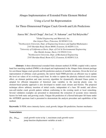
Workshop 1Abaqus model build and SimulationIntroductionThis workshop will give you an opportunity to generate an Abaqus model using the GraphicalUser Interface (GUI), Abaqus/CAE, apply loads, boundary conditions and interactions andsubmit and monitor an analysis. The results will be viewed in Abaqus/CAE.PreliminariesStart a new session of Abaqus/CAE using the following command:abaqus caewhere abaqus is the command used to run Abaqus.In the Start Session dialog box, underneath Create Model Database, click WithStandard/Explicit Model. Dassault Systèmes, 2015Academic Workshop 1 - Abaqus
W1.2To save the model database, select File Save As from the main menu bar and type the filename LugAssembly in the Save Model Database As dialog box. Click OK.The .cae extension is added to the file name automatically.Creating a partIn this section you will create a three-dimensional, deformable solid body by sketching the twodimensional profile of the lug and extruding it.1. Abaqus/CAE automatically loads the Part module. Any other module can be accessedfrom the Module list located in the context bar, as shown in Figure W1–2.Figure W1–2. Module list2. From the main menu bar, select Part Create to create a new part. In the Create Partdialog box that appears, name the part lug, and specify an approximate size of 400. Dassault Systèmes, 2015Academic Workshop 1 - Abaqus
W1.3Accept the default settings of a three-dimensional, deformable body with a solid,extruded base feature. Click Continue.a. Abaqus/CAE displays text in the prompt area near the bottom of the window to guideyou through the procedure, as shown in Figure W1–4. At any stage of the processyou can click the cancel button to cancel the current task; click the backup button tocancel the current step in the task and return to the previous step.Figure W1–4 Prompt area.b. The Sketcher toolbox appears in the left side of the main window, and the Sketchergrid appears in the viewport. The grid is a 2D plane on which you create the baseshape for your part. Abaqus/CAE overlays the sheet with a grid of invisible gridpoints to help you position the cursor as you draw, move, resize, or reshape objects.By default, when you move the cursor near a grid point, the cursor automaticallymoves, or snaps, to the point. This behavior allows you to easily position the cursorprecisely on a grid point while also providing you with full control when the cursor isnot close to any grid point.3. In the viewport, sketch the rectangular body of the lug as follows:c. To sketch the profile of the lug, you first need to select the ‘create lines - connected’drawing tool, as shown in Figure W1–5. Create 3 lines with vertices at (100,0); (0,0);(0,50) and (100,50), then click mouse button 2 twice to complete the task.Figure W1–5 Create Lines - Connected sketch tool.d. Next create the radiused end of the lug using the Create Arc; Centre and 2 endpoints tool,. As shown in Figure W1-6, define the arc centre at (100,25) thenpick the end points of the open box to complete the lug profile. Click Mouse button 2to complete the operation. Dassault Systèmes, 2015Academic Workshop 1 - Abaqus
W1.4Figure W1–6 Adding semi-circular end to lug profile.e. Lastly, add the 30mm diameter hole for the lug using the Create Circle, Centre andPerimeter tool. Select (100,25) as the circle centre followed by (100,40) as the circleperimeter to end up with the profile shown in Figure W1-7Figure W1–7 Adding Circular Hole to lug profile.f. Click Done in the prompt area to exit the sketcher.g. Enter an extrusion depth of 20 in the Edit Base Extrusion dialog box, and click OK.Abaqus/CAE displays an isometric view of the new part, as shown in Figure W1–8.Save the database Dassault Systèmes, 2015.Academic Workshop 1 - Abaqus
W1.5Figure W1–8 Extruded part.4. Now create the second part – the Pin. From the main menu bar, select Part Create tocreate a new part. In the Create Part dialog box that appears, name the part pin. Acceptthe default settings of a three-dimensional, deformable body with a solid, extruded basefeature, approximate size of 200 mm. Click Continuea) We will first create a rough approximation of the pin profile and then useconstraints and dimensions to refine the sketch. Use the Create Circle, Centreand perimeter tool to generate a circle of any size. Suggest you use (0,0) as thecircle centre.b) Then use the Add Dimension toolradius to 15.0 mm. Dassault Systèmes, 2015and select the circle circumference. Set theAcademic Workshop 1 - Abaqus
W1.6c)Then click ‘done’ to accept the profile and exit the sketcher.d) Enter an extrusion depth of 40 in the Edit Base Extrusion dialog box, and clickOK.Save the Abaqus/CAE database.5. Now create the third part – the second lug. From the main menu bar, selectPart Create to create a new part. In the Create Part dialog box that appears, name thepart lug2 and specify an approximate size of 400. Accept the default settings of a threedimensional, deformable body with a solid, extruded base feature. Click Continuea) Create a rectangleof dimensions 65 x 20. . Note that in this instance thebottom right hand corner of the rectangle is at (0,0). Then superimpose a circleof diameter 50 centred half way up the rectangle end at x -65. Dassault Systèmes, 2015Academic Workshop 1 - Abaqus
W1.7b) Then break each of the horizontal rectangle edges and the circle at theintersection points using the ‘split’ button. Note that you will haveto press and hold the mouse button to select this option.c)After breaking all 4 curves use the delete buttonunwanted curves. Dassault Systèmes, 2015to remove the internalAcademic Workshop 1 - Abaqus
W1.8d) Next use the fillet radius between 2 curves toolthe sharp intersections of the curves both sides.to create 10mm fillet radii ate) Create a 30 mm diameter circle for the pin hole at the curved section centre.f) Then click ‘done’ to accept the profile and exit the sketcher.g) Enter an extrusion depth of 40 in the Edit Base Extrusion dialog box, and clickOK.Save the Abaqus/CAE database. Dassault Systèmes, 2015Academic Workshop 1 - Abaqus
W1.96. Now we will use the geometry editing toolset to add features to the lug2 part. Thesefeatures will be used to finalize the geometry of the lug2 part.a. First create a datum plane to use as the basis for the sketch, which will be used togenerate the sketch for the extrusion. Use the ‘Create datum plane: offset fromplane’ toolrectangular body.and select the top plane of the lugb. Enter an offset value of 30 mm away from the face. Dassault Systèmes, 2015Academic Workshop 1 - Abaqus
W1.10c. From the main menu select Tools Datum Axis Axis of cylinder and select thehole surface to be the cylindrical face.d. Next use the Create Cut: Extrude toolto cut away the central part of the lugbody. Select the newly created datum plane as the sketch plane, and the back edgeof the lug to be the axis that will appear vertically and to the right.e. You will now use the sketcher options toolto reposition the sketch on the grid.On the General tab click Origin to Align grid. Select the point where your yellowdotted datum axis crosses the blue dotted sketch pad y-axis.On the General tab change the Grid Sheet size to 200 and the Grid spacing to 5 to setup a regular grid, then create a rectanglewith 2 corners (30, 10.5) and (-30, -10.5)Note that you will have to enter these coordinates in the text prompt box, then done toexit the sketcher. Dassault Systèmes, 2015Academic Workshop 1 - Abaqus
W1.11f. Accept the default ‘Through All’ for the type of cut extrusion to finish the cut.g. Now use the ‘Create round or fillet’ toolto fillet the sharp corners left by the cut.Select the corner on one side of the cutand define the fillet radius as 5 mm. Do the same operations on the other side ofthe cut to finish with the part as shown. Then save your Abaqus/CAE database. Dassault Systèmes, 2015Academic Workshop 1 - Abaqus
W1.12Creating a material definitionYou will now create a single linear elastic material with a Young’s modulus of 209 103 MPa andPoisson’s ratio of 0.3.To define a material:1. In the Model Tree, double-click Materials to create a new material in the model Model-1.Abaqus/CAE switches to the Property module, and the material editor appears.1. In the Edit Material dialog box, name the material Steel. Notice the various optionsavailable in this dialog box. Dassault Systèmes, 2015Academic Workshop 1 - Abaqus
W1.13Figure W1–8 Pull–down menu.2. From the material editor’s menu bar, select Mechanical Elasticity Elastic, as shownin Figure W1–8.Abaqus/CAE displays the Elastic data form.3. Enter a value of 209.E3 for Young’s modulus and a value of 0.3 for Poisson’s ratio in therespective fields, as shown in Figure W1–9. Use [Tab] to move between cells, or use themouse to select a cell for data entry.Figure W1–9 Material editor.4. Click OK to exit the material editor.Defining and assigning section propertiesNext, you will create a homogeneous solid section for each part and assign it to the respectivepart. The section will refer to the material Steel that you just created.To define the homogeneous solid section:1. In the Model Tree, double-click Sections to create a new section in the model Model-1.The Create Section dialog box appears.2. In the Create Section dialog box:a. Name the section lugSection.a.Accept the default category Solid and the default type Homogeneous.b.Click Continue.The solid section editor appears. Dassault Systèmes, 2015Academic Workshop 1 - Abaqus
W1.143. In the Edit Section dialog box:a. Accept the default selection of Steel for the Material associated with the section.c.Accept the default value of 1 for Plane stress/strain thickness.Note: For three-dimensional solid geometry, this value is not used. It is onlyrelevant for two-dimensional geometry.d.Click OK.To assign the section definition to the cantilever beam:1. In the Model Tree, expand the branch for the part lug (click the “ ” symbol to expand theParts container and then click the “ ” symbol next to the part lug).2. Double-click Section Assignments to assign a section to the part lug.Abaqus/CAE displays prompts in the prompt area to guide you through the procedure.3. Click anywhere on the beam to select the entire part as the region to which the sectionwill be assigned.4. Click mouse button 2 in the viewport or click Done in the prompt area to accept theselected geometry.The section assignment editor appears.5. In the Edit Section Assignment dialog box, accept the default selection of LugSectionas the section definition, and click OK.Abaqus/CAE colors the lug green to indicate that the section has been assigned.Now repeat these operations to create sections called pinsection and lug2section usingmaterial ‘Steel’ and assign them to parts pin and lug2 respectivelyAssembling the modelThe assembly for this analysis consists of an instance of the part lug, an instance of the partpin and an instance of the part lug2. In order to make the assembly of these parts a little easierwe will first create datum axes in the part module for each part.Switch to the Part module and from the menu bar select Tools Datum Axis Axis ofCylinder. You have already defined the axis for part lug2, so for lug and pin define a datum axisusing the cylindrical face. Dassault Systèmes, 2015Academic Workshop 1 - Abaqus
W1.15To assemble the model:1. In the Model Tree, expand the branch for the Assembly of the model Model-1 anddouble-click Instances to create a new part instance.Abaqus/CAE switches to the Assembly module, and the Create Instance dialog boxappears.2. In the Create Instance dialog box, select all 3 parts, i.e. lug, pin and lug2, accept theInstance type to be Dependent (mesh on part) and click OK.Abaqus/CAE displays the new part instances in the viewport. These now need to beassembled correctly.3. From the top menu bar select Constraint Edge to Edge. Pick the datum axis of thepin on the movable instance; then pick the datum axis of the first lug on the fixedinstance. Check the alignment of the arrows and then OK to move the instance. Notethat the coaxial constraint could also have been used here.4. Repeat this operation using the datum axis of the second lug on the movable instanceand the datum axis of the first lug on the fixed instance.5. The components should now have a common centerline on their datum axes.6. Use the Instance translate dropdown to position your instances correctly in theassembly. Note that you will have to calculate the required translation vectors first.7. You can use the colour paletteparts or part instances to make visualization clearer. Dassault Systèmes, 2015to change from default toAcademic Workshop 1 - Abaqus
W1.168. Lastly rotate lug2 using Instance Rotate through 90 degrees around any two pointson the datum axis so that lug2 points up the y-axis as shown. NB Abaqus/CAE rotateuses a Right Hand Rule. Dassault Systèmes, 2015Academic Workshop 1 - Abaqus
W1.17Configuring the InteractionsIn this simulation we have 3 components which will interact with each other. In this case we willbe using contact interactions and specifying General Contact between the part instances.To create the general contact:1. In the Model Tree, double-click Interactions to create a new interaction in the modelModel-1.Abaqus/CAE switches to the Interaction module, and the Create Interaction dialog boxappears.2. In the Create Interaction dialog box:a. Name the interaction contact.b. Select General contact (Standard) – which is only available in the Initial step.c. Click Continue.3. Accept the default contact domain All *with self. This means that all external faces of allpart instances may come into contact with each other – or themselves.4. We now need to create an Interaction property to assign to this contact condition:a. Click the Create Interaction Property buttonon the contact properties tab.b. Name the Property friction and accept the default type contact, then continuec. Create a Mechanical Tangential property with friction formulation penalty and acoefficient of friction 0.2, then click OKd. In the Edit Interaction box the Global Property Assignment dropdown has beenpopulated with our new interaction property, friction, so select this and then click OKto complete the contact interaction. The save the Abaqus/CAE database.Configuring the analysisIn this simulation we are interested in the static response of the first lug to a pressure appliedover the flat surface of the second lug. Although this is a single event we will apply the totaldisplacement over two load steps following the initial step so, consequently, this model willconsist of three steps: An initial step, in which you will apply boundary conditions to the assemblyA general, static analysis step in which you will apply a very small pressure to ‘settle’ thecontact.A general, static analysis step in which you will apply a pressure of 37.5 N/mm2 normalto the end face of lug2.Abaqus/CAE generates the initial step automatically, but you must create the subsequentanalysis steps yourself.To create a general, static analysis step:1. In the Model Tree, double-click Steps to create a new step in the model Model-1.Abaqus/CAE switches to the Step module, and the Create Step dialog box appears. Dassault Systèmes, 2015Academic Workshop 1 - Abaqus
W1.182. In the Create Step dialog box:a. Name the step settle.b. From the list of available general procedures in the Create Step dialog box,select Static, General if it is not already selected.c. Click Continue.The step editor appears.3. In the Edit Step dialog box:a. In the Description field of the Basic tabbed page, enter settle contact.b. Check the button to turn Nlgeom on.c. Click the Incrementation tab, and delete the value of 1 that appears in the Initialtext field. Type a value of 0.1 for the initial increment size.d. Click the Other tab to see its contents; you can accept the default valuesprovided for the step.e. Click OK to create the step and to exit the step editor.4. Repeat these operations to create a third step called full-load. Note that for this stepNlgeom is turned on by default.Applying the boundary conditions and loadsto the modelNext, you will define the boundary condition and loading that will be active during the settlecontact step.To apply boundary conditions to the fixed end of the lug:1. In the Model Tree, double-click BCs to create a new boundary condition in the modelModel-1.Abaqus/CAE switches to the Load module, and the Create Boundary Condition dialogbox appears.2. In the Create Boundary Condition dialog box:a. Name the boundary condition Fixed.e.Select Initial as the step in which the boundary condition will beactivated.f.In the Category list, accept the default category selection Mechanical.g.In the Types for Selected Step list, select Displacement/Rotation asthe type.h.Click Continue.Abaqus/CAE displays prompts in the prompt area to guide you through theprocedure. The face at the end of the first lug will be fixed.3. In the select options boxClosest to the ScreenFigure W1–10. Dassault Systèmes, 2015deselect Select the Entityso that you can pick the desired face, as shown inAcademic Workshop 1 - Abaqus
W1.19Figure W1–10 Correct face selected.When you move the cursor over this face, Abaqus/CAE will change the cursor, addingellipsis marks (.) to the right of the arrow, to indicate that more than one selection objectis available. If you click when the selection is ambiguous, Abaqus/CAE will select theface closest to you and display buttons in the prompt area that allow you to choose therequired face. To cycle through the valid selections, do the following:a. From the prompt area, click Next or Previous until the desired face is selected.i.Click OK to accept the current selection.4. Click mouse button 2 in the viewport or click Done in the prompt area to accept theselected geometry.The Edit Boundary Condition dialog box appears. When you are defining a boundarycondition in the initial step, all six degrees of freedom are unconstrained by default.5. In the Edit Boundary Condition dialog box:a. Toggle on U1, U2, and U3, since only the translational degrees of freedom needto be constrained (the lug will be meshed with solid elements later).j.Click OK to create the boundary condition definition and to exit the editor.Abaqus/CAE displays arrows at each corner and midpoint on the selected faces toindicate the constrained degrees of freedom, as shown in Figure W1–11.Use the same procedure to apply a boundary condition called guide to the free end of lug2 inthe initial step and in degrees of freedom 1 and 3 only (we will be loading lug2 in degree offreedom 2, the Y-axis).To apply a load to the top of lug2:1. In the Model Tree, double-click Loads to create a new load in the model Model-1.The Create Load dialog box appears. Dassault Systèmes, 2015Academic Workshop 1 - Abaqus
W1.202. In the Create Load dialog box:a. Name the load small-pressure.k.Select settle as the step in which the load will be applied.l.In the Category list, accept the default category selection Mechanical.m.In the Types for Selected Step list, select Pressure.n.Click Continue.Abaqus/CAE displays prompts in the prompt area to guide you through the procedure.3. In the viewport, select the top face of the beam as the surface to which the load will beapplied. The desired face is highlighted in Figure W1–11.Figure W1–11 Boundary conditions; and distributed load.4. Click mouse button 2 in the viewport or click Done in the prompt area to indicate thatyou have finished selecting regions.5. In the Edit Load dialog box:a. Enter a magnitude of 0.001 for the load.o.Accept the default Amplitude selection (Ramp) and the defaultDistribution (Uniform).p.Click OK to create the load definition and to exit the editor.Abaqus/CAE displays downward–pointing arrows along the top face of the beam toindicate the load is applied in the negative 2–direction.The small-pressure load is intended to settle the contact between lugs and pin – the full loadwill be applied in the third full-load step. In order to do this expand Loads in the model tree,then expand load small-pressure and states and double-click ‘full-load (Propagated)’ to edit Dassault Systèmes, 2015Academic Workshop 1 - Abaqus
W1.21the value of the load in this step. Apply the full load of 37.5 N/mm2. Then click OK to completethe modification. Then save the Abaqus/CAE databaseMeshing the modelYou use the Mesh module to generate the finite element mesh. You can choose the meshingtechnique that Abaqus/CAE will use to create the mesh, the element shape, and the elementtype for each of the part instances. Abaqus/CAE uses a number of different meshingtechniques. The default meshing technique assigned to the model is indicated by the color ofthe model when you enter the Mesh module; if Abaqus/CAE displays the model in orange, itcannot be meshed without assistance from the user.To assign the mesh controls:1. In the Model Tree, double-click Mesh in the branch for the part Lug.Abaqus/CAE switches to the Mesh module and displays the part Lug.2. From the main menu bar, select Mesh Controls.3. In the Mesh Controls dialog box, accept Hex as the default Element Shape selection.4. Accept Sweep as the default Technique selection.5. Change the Algorithm to Medial axis.6. Click OK to assign the mesh controls and to close the dialog box.To assign an Abaqus element type:7. From the main menu bar, select Mesh Element Type, select the region if required.8. In the Element Type dialog box, accept the following default selections that control theelements that are available for selection: Standard is the default Element Library selection. Dassault Systèmes, 2015Academic Workshop 1 - Abaqus
W1.22 3D Stress is the default Family of elements.Change the Geometric Order from Linear to Quadratic9. In the middle portion of the dialog box, examine the element shape options (Hex,Wedge, Tet). A brief description of the default element selection is available at the bottomof each tabbed page.10. In the Hex tabbed page, accept the default Reduced integration.A description of the element type C3D20R appears at the bottom of the dialog box.Abaqus/CAE will now use C3D20R elements when we apply the mesh.11. Click OK to assign the element type and to close the dialog box.To mesh the model:12. From the main menu bar, select Seed Part to seed the part.The Global Seeds dialog box appears. The default global element size is based on thesize of the part.13. In the Global Seeds dialog box, enter an approximate global size of 4 and click OK.Abaqus/CAE applies the seeds to the part, as shown in Figure W1–12.Figure W1–12 Seeded part instance.14. From the main menu bar, select Mesh Part to mesh the part.15. Click Yes in the prompt area or click mouse button 2 in the viewport to confirmthat you want to mesh the part instance.Abaqus/CAE meshes the part instance and displays the resulting mesh, asshown in Figure W1–13. Dassault Systèmes, 2015Academic Workshop 1 - Abaqus
W1.23Figure W1–13 Part instance showing the resulting mesh.Mesh the other 2 partsNow mesh the other 2 parts using the same procedure.You will need to apply mesh controls to the part pin to define a sweep mesh with medial axis,the part pin should have a mesh seed of 2 mm and an element type of C3D20R.The part lug2 will not mesh using hex elements (without significant extra effort from the user)and so is coloured orange when you open the mesh controls dialogue box. So you will changethe Element Shape to Tet (tetrahedral) and then accept the default settings. Note how thecolour of the part lug2 has now changed to pink to indicate that it is meshable. Apply a globalmesh seed of 3 mm and continue to mesh the part lug2 using an element type of C3D10I (aquadratic tetrahedral element with improved surface stress formulation).Now in the top menu bar click on Assemblyand check that Show NativeMeshis toggled on. Your meshed assembly now should look like this:- Dassault Systèmes, 2015Academic Workshop 1 - Abaqus
W1.24Then save the Abaqus/CAE database.Creating and submitting an analysis jobThe definition of the model Model-1 is now complete. Next, you will create and submit ananalysis job to analyze the model.To create and submit an analysis job:1. In the Model Tree, double-click Jobs to create a new analysis job.Abaqus/CAE switches to the Job module, and the Create Job dialog box appears.2. In the Create Job dialog box, name the job Press and select the model Model-1. ClickContinue.The job editor appears.3. In the Description field of the Edit Job dialog box, enter Workshop 1.4. Click the tabs to see the contents of each folder of the job editor and to review thedefault settings. Click OK to accept the default job settings.5. From the menu toolbar select Job Manager.The menu for the job manager appears.6. From the job manager, select the job press then select Submit. Dassault Systèmes, 2015Academic Workshop 1 - Abaqus
W1.25As the job runs the status will be shown in the job manager window. Select Monitor tofollow the status of the job as it runs. Click on each of the tabs to see what is reportedduring/after analysis.On successful completion of the job the log tab looks as below:- Dassault Systèmes, 2015Academic Workshop 1 - Abaqus
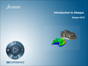
W1.26Viewing the analysis resultsYou are now ready to view the results of the analysis in the Visualization module.1. In the Model Tree, click mouse button 3 on the job press and select Results from themenu that appears.Abaqus/CAE switches to the Visualization module, opens the output database createdby the job (press.odb), and displays the undeformed shape of the model, as shown inFigure W1–15. Dassault Systèmes, 2015Academic Workshop 1 - Abaqus
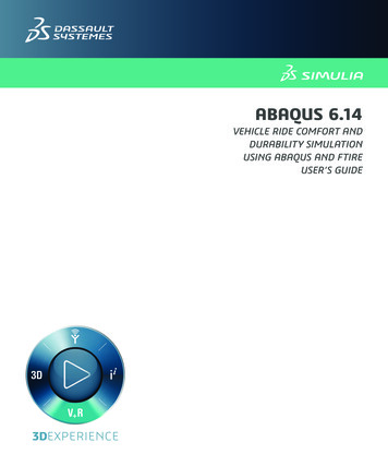
W1.27Figure W1–15 Undeformed model shape.2. From the main menu bar, select Plot Deformed Shape to view a deformed modelshape plot. The deformation scale factor can be changed by selecting Options Common on the main menu then specifying a Uniform or Nonuniform scale factor on theBasic tab.3. From the main menu bar, select Plot Contours on Deformed Shape to view acontour plot of the von Mises stress, as shown in Figure W1–17. Dassault Systèmes, 2015Academic Workshop 1 - Abaqus
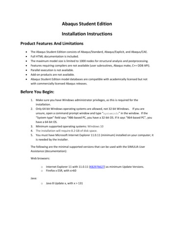
W1.28Figure W1–17 Mises stress contour plot.4. From the main menu bar, select File Save to save your model in a model database file.Export a part for use in Workshop 2Just before we leave the session you need to export the part lug for use in the next workshop:-1.2.3.4.Select the Part module from the dropdownSelect the part lugSelect File Export Part from the main menu barName the part lug and select ACIS Version R23. Click OKCheck the Message area to check to which directory file lug.sat has been written.Close the Abaqus/CAE session by selecting File Exit from the main menu bar. Dassault Systèmes, 2015Academic Workshop 1 - Abaqus
User Interface (GUI), Abaqus/CAE, apply loads, boundary conditions and interactions and submit and monitor an analysis. The results will be viewed in Abaqus/CAE. Preliminaries Start a new session of Abaqus/CAE using the following command: abaqus cae where abaqus is the command used to run Abaqus.