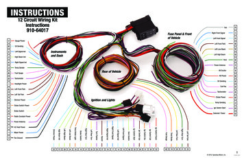
Transcription
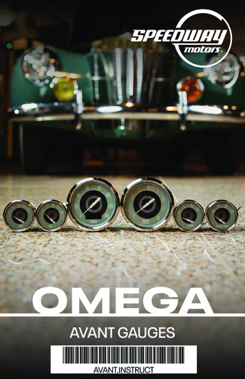
OMEGAAVANT GAUGES*AVANT.INSTRUCT*AVANT.INSTRUCT
Omega Avant GaugesINDEXIntroduction. 2Terms. 3AUTOCAL Quick Set-Up. 4Installation Basics. 5RUN Menu Functions. 5Set Up Menu Functions. 7Speedometer Troubleshooting Basics. 10Gauge Back. 11Programmable Fuel Gauge. 12Speedometer Wiring/Connections. 13Quad Gauge Wiring. 142-1/16" Gauges. 15Wiring Multiple Gauges. 16Senders and Signals. 17Mechanical Speedometer. 18Tachometers. 19Senders and Signals. 22Auxillary Inputs. 23*AVANT.INSTRUCT*AVANT.INSTRUCT1
5O4O3O6O 7O 8OMPH9O1OO1OO12O2O1O13OO14OOMEGA KUSTOMINSTRUMENTSINTRODUCTIONAdvanced Feature Speedometers offer features found in complete clusters, OEinstrument systems and data loggers, all in a standalone unit. While all of the featureslisted in this manual are available, they are not all required to be used. You can use yourspeedometer simply as a way to monitor your speed or as a performance meter.Some of the advanced features include: OLED high resolution display Drive-a-mile self calibration Integration with OE and aftertmarket speed signal and PCM outputs GPS input compatible Overspeed warning output (AMP Plug models) MPH/KPH speed toggle Performance meter 0-60, 1/8 and 1/4 mile times/speed captureInstallation:Advanced feature speedometers are offered in perimeter lit (incandescent bulb) orbacklit (LED backlighting) depending on the series.They are identified by the back: If bulb sockets are installed, you have a perimeter incandescent unit. If the holes are plugged, you have an LED backlit unit.Connections:Speedometers are offered in either a studded or AMP plug connection. All of the wires onthe AMP plug may be used depending on the application. Check further in the manual formore details.2Need Tech Help? Just call 800.979.0122
Omega Avant GaugesTERMS WHEN USING THIS BOOKLETScroll - Pressing and releasing of the remote button to move through menu options.Short push - Briefly holding the remote button and releasing it.Long Push - Holding the remote button for one second or until a menu display changes.With all of the features packed into Advanced Feature Speedometers, options are dividedinto different menus.Your speedometer has a main "RUN" menu and a "SETUP" menu. The RUN menu utilizes the features used during normal operation. The SETUP menu stores all of the items that are setup during theinstallation process. Items can be changed any time after, if desired, and are separate toprevent inadvertently changing them during normal use.During installation please contact our experienced tech team with questions.See our full inventory at SpeedwayMotors.com3
5O4O3O6O 7O 8OMPH9O1OO1OO12O2O1O13OO14OOMEGA KUSTOMINSTRUMENTSAUTOCAL (Drive-A-Mile Self-Calibration) Quick Set-UpCheck that your digital input filter is set to the proper input setting (see more later inmanual if needed). All advanced speedometers are shipped with the input set on HIGH(suitable for most applications) with 16,000 PPM.Enter the setup menu by holding the remotebutton and turning on the key (start vehicle).Scroll to auto calibrate (3RD ITEM).Hold button until screen displays READY TO DRIVE? YESHold button until display shows COUNTING 0Drive exactly one mile (or KM), speed does not effect accuracy. You may or may not seeaction on the speedometer before or during calibration. Display will show counting withthe digits increasing below. This is the speedometer counting the number of pulses it isreceiving from the signal source. If the display does not count, check your signal sourceor input filter, the speedometer is not reading a signal.At the end of the mile (vehicle can be moving or stationary),hold the button until SET YES appears.If NO PULSES is displayed, a signal was not read by the speedometer. Check your inputfilter selection and speed signal.Hold button until SAVED! appears.The speedometer is now calibrated. Pressing the button will take you through the rest ofthe setup menu features. To resume normal operation, turn off the vehicle and restart.4Need Tech Help? Just call 800.979.0122
Omega Avant GaugesINSTALLATION BASICS: Use a minimum of 20 gauge insulated, stranded wire. All connections should beconnected with a crimp connection or solder and heat shrink. Keep speed signal wire(s) away from potential "noise" sources like ignition wires,tach signal wires, fan motors, pumps, etc. Studded speedometers use #8 studs. Use applicable eye terminals for wiring. Use a maximum of 1A fuse for the entire cluster. This is usually already in your fuseblock. Commonize wiring, ground power and lights can be common on all gauges and"daisy chained."Speedometer Operation Menus:With all of the features packed into advanced feature platform Speedometers, we havedivided them into different menus.Your speedometer has a main "RUN" menu, and a "SETUP" menu. The RUN menu utilizes the features used during normal operation. The SETUP menu stores all of the items that are setup during the installationprocess. Items can be changed any time after, if desired, and are separate to preventinadvertently changing them during normal use.RUN Menu Functions:Features can be accessed in the run menu during normal operation with the key on. Toscroll to the various displays in the OLED screen, use a short push or tap of the remotebutton.Main Odometer:Displays total distance traveled in miles or kilometers depending on the model. Thisdisplay does not show tenths.Trip Meter:Displays current trip distance. Press and hold the button and the odometer will reset to 0.This display will show tenths and will not have any zeros in front of the distance traveled.See our full inventory at SpeedwayMotors.com5
5O4O6O 7O 8O3OMPH9O1OO1OO12O2O1O13OO14OOMEGA KUSTOMINSTRUMENTSRUN Menu Functions Continued.Service:This is used to see when your next service interval is due (oil change, tire rotation ) Theinterval is set in the SETUP menu in the next section. This screen is to display the intervalremaining.When the service interval has been reached, the SERVICE REQUIRED warning willdisplay at vehicle startup. The interval can be reset in the SETUP menu.MPH:This will display your current Miles Per Hour you are traveling.KPH:This will display the current Kilometers Per Hour you are traveling.Peak Speed:This will display the highest speed achieved since last reset. Press and hold the buttonand the odometer will reset to 0.Performance Timers: (where applicable)Displays 1/4 and 1/8 mile time and trap speed as well as 0-60 time. Enter theperformance mode you wish to measure, hold the button until the dialog to start isdisplayed, enter YES to start or NO to reset. Start driving. (Professional driver only ona closed course). Note: this feature is available on select models only, check productfeature documentation.6Need Tech Help? Just call 800.979.0122
Omega Avant GaugesSet Up Menu Functions:The SETUP menu contains menus used for functions not used during normal operation.These features are in this sub-menu to avoid inadvertently changing them during normaloperation.While the vehicle is off press and hold the button. Turn the vehicle on. The odometerwill display SETUP MENU. Short pushes on the button will scroll through these featuresand long hold of the button will select the item. To exit the SETUP MENU turn off thevehicle and restart. You may operate the speedometer in setup mode if required, thespeedometer will operate to make fine tuning easier.Service Reset: (Push and hold button to enter)This is used to reset service interval if you have saved any (oil changes, tire rotations, tuneups ) You can set service intervals later in this menu (Service Set section). Short push toscroll, long push to select.Manual Calibrate: (Push and hold button to enter)Manual calibration of the speedometer is used to manually enter the pulse setting. Youmust know the pulse setting of the speed signal to use this feature. Common uses are onOE (pre-configured) senders, GM PCMs GPS senders.Note: Using this method will usually get you close enough and fine tuning or autocalibration may be required. Although many speed senders are standard output, variousgear ratios and tire sizes will change the pulse settings depending on the vehicle build.The speedometer will accept between 2,000-250,000 PPM. See next page for a chartwith common pulse settings.To enter the manual calibration mode, hold the button until the current pulse setting isshown. We ship all speedometers with a 16,000 PPM setting. If the number shown is not16,000 the speedometer has already been auto-calibrated by the end user. If the pulsecount shows zero, the previous autocal attempts resulted in not receiving a speed signal.Check your sender and input filter.Continue to next page.See our full inventory at SpeedwayMotors.com7
5O4O3O6O 7O 8OMPH9O1OO1OO12O2O1O13OO14OOMEGA KUSTOMINSTRUMENTSManual Calibrate Continued.The current pluses will be shown, with the first number highlighted. To change thatnumber short push scrolling will increase the digit. Stop on the number required and holdthe button to select the next number and follow the same sequence until all numbers arecorrect and your are on the last digit to the right.The final dialog box will display asking to set. Select Y to accept, N to cancel. Hold thebutton on Y and the setting will be saved. The speedometer is now manually calibrated.Auto Calibrate:This feature allows the speedometer to automatically calibrate the speedometerby driving a measured mile (or kilometer). See quick setup earlier in this manual forinstructions.Input Filter:The digital filter in the speedometer is used to properly read the signal from virtually anypulsed source. Enter the filter by holding the button. Scroll to the filter selection desired,refer to the chart below. Select L, M or H (low, medium, high). Hold the button to selectFILTER, set YES or NO, hold to select SAVED! Will display to indicate a successful session.You can change this at any time to adjust as needed or to experiment for the best resultsfor your application.SourceTypical PPMSignal TypeInput Filter SetGM PCM (All)4,0005-12V Hall Effect5V M, 12V HAftermarket 3 Wire16,00012V Hall EffectHAftermarket 2 Wire8,000 or 16,000AC SinewaveLOE 2 Wire (GM)40,000AC SinewaveLNV4500108,000AC SinewaveLTremec16,000 or 40,000Low AC SinewaveLGPS Sender8,000 or 16,000Varies5V M, 12V H8Need Tech Help? Just call 800.979.0122
Omega Avant GaugesSETUP Menu Functions Continued.Overspeed:Available on AMP-Plug and commercial units only. The overspeed output can be used totrigger a relay that can operate a buzzer or lamp. Never connect the overspeed outputdirectly to the device to be used, always connect with a relay or speedometer. Damagewill result. The output on the overspeed is 12V less than .2 amp.To set the overspeed enter the SETUP MENU and scroll to overspeed. Hold in the buttonto enter the menu. The current overspeed setting will be displayed:To change the overspeed setting, scroll to YES, then hold the button, the current warninglevel will be shown with the first digit highlighted. To change the digit, tap the buttonto increase the number. To move to the next number, hold the button until the next ishighlighted. Proceed with the same procedure until all 3 digits are changed. On the lastnumber hold until the display shows the speed and set? YES. The saved speed will beshown. If there is an error you can select NO or turn off the gauge and no changes will bemade.Set Odometer:The SET ODOMETER function is a one-time setting that the end user can change duringthe first 100 miles of operation. The user can set the mileage to the existing vehiclemileage to maintain a proper vehicle record. Once the mileage has passed 100 miles,the feature will no longer be available. To enter the set odometer menu, scroll to SETODOMETER and hold in the button. You will see one time set ? YES. Hold in the button.000000 will be shown with the first digit highlighted. To change the digit, tap the buttonto increase the number. To move to the next number, hold the button until the next ishighlighted. Proceed with the same procedure until all digits are changed. On the lastnumber hold until the display shows the mileage SET YES? Hold in the button and SAVED!will appear. Turn off and restart the vehicle, mileage is now set.See our full inventory at SpeedwayMotors.com9
5O4O3O6O 7O 8OMPH9O1OO1OO12O2O1O13OO14OOMEGA KUSTOMINSTRUMENTSSETUP Menu Functions Continued.Program Version Number:This displays the current software version stored in the instrument. The version willvary based on the model you have. It is only required if you have an issue with yourspeedometer as this information will be useful when contacting for service.Speedometer Troubleshooting Basics:Speedometers are just like any other gauge in respect that it has the same threerequirements; power, ground and a signal. The troubleshooting process is the same, startat the end of the system and work your way toward the gauge. As with all gauge systemsthere are 3 components: The gauge, the wire and the sender or signal source. All threeneed to be checked for the entire system to operate properly.- Turn on the key, does the gauge power up? If not then check power or gauge fault.- Turn on the lights, does the gauge light up? If not then check your ground.Speedometer will not calibrate:All speedometers require a speed signal to operate properly. We first need to check thesenders.Hall Effect Cable Output Replacement Style:- Pull the plug from the back of the sender, check for power on the red wire, groundon the black.- Pull the sender from the trans, turn on the key and spin the sender with a drill.Speedo operates, then check mechanical engagement issue with the transmissiondrive gear, check as needed. Speedo does not operate, check the sender wireusing a test lamp.Hall Effect Speed Sender Test:- The hall effect sender will alternate positive and negative pulse when turning thesender slowly by hand. Use a test lamp or multi meter to check by probing the signalwire and the hot then the ground lead.2-Wire Speed Sender, AC Sine Wave and Magnetic Pickup:- Check that the ground lead is as short as possible- Check for continuity between the sender and the gauge- Pull the sender from the trans, turn on the key and spin the sender with a drill.Speedo operates then mechanical engagement issue with the transmission drivegear, check as needed. If speedo does not operate, then check the sender wireusing a test lamp.10Need Tech Help? Just call 800.979.0122
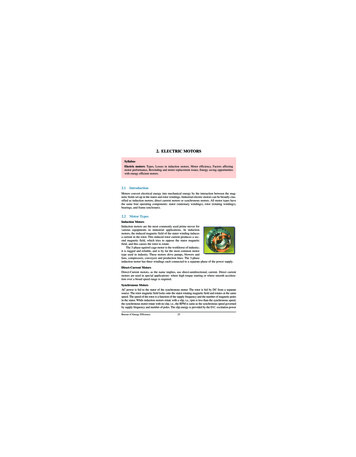
Omega Avant GaugesSpeed Sender Test 2-Wire:- Set your multi meter on AC voltage, lowest setting or 20V. Probe the sender wirewith the red lead, ground the back lead. Spin the sender; you should see between8-18V on the signal wire. Low or no voltage indicates a bad sender or sender that willbe going bad soon. This test can also be performed on the cable output style byremoving and spinning with a drill to check for a mechanical issue (see above).Note on Ford Style Cable Output Senders:Check that the drive gear is installed on the sender. The spin with a drill test should bemade with the drive gear on and off to rule out an out-of-square drive on the gear.PCM/ECU:Testing the signal is the same as above methods but it is also important to check theVSS on the transmission to ensure a signal is reaching the PCM first. Without thatsignal the PCM will not be able to send a signal to the speedometer.The Back of Your Gauge:All advanced feature gauges with 12-pin AMP plugs have the same features on the rear.You will find the plug location, back clamp attachments, bulb locations (perimeter litmodels only) and programming/DIP-switch settings.Lighting: All perimeter lit incandescent gauges have standard 194 bulbs installed in aremovable socket that is powered on the circuit board. To remove, twist counterclockwiseand remove. Bulbs can be changed to different colors or even LED bulbs.All LED backlit gauges have LED lighting incorporated onto the circuit board and are notchangable. To dim the LEDs you will need a LED dimmer. When wiring LED bulbs do notwire to the stock dimmer circuit as the bulbs will not dim or may not operate. You shouldconnect to the parking lamp function for a constant supply of power.The features areshown at right. Toaccess the DIPswitches, remove therubber plug. All 3-3/8and 4-3/8 gaugeshave the same layout.11
5O4O3O6O 7O 8OMPH9O1OO1OO12O2O1O13OO14OOMEGA KUSTOMINSTRUMENTSProgrammable Fuel Gauge for 3n1 & Quad GaugesAll advanced feature platform multifunction gauges feature stepper motormicorprocessor driven internals that feature programmable fuel level sender inputs. Thisallows for the setting to be changed at time of installation removing the need for a newsender or dropping the tank. Follow the chart below for proper DIP-switch settings foryour fuel tank. Change the DIP switches with the power off. Use a pointed object like apick or small screwdriver to change the settings. Ensure the switch is fully ON or OFF.12Sender Type Make/YearRange E-F1234Early GM/Ford Pre-'650-30OFFOFFONOFFGM '65-890-90OFFONOFFOFFGM '90s-Up40-250OFFONONOFFFord AMC Mopar '65-8673-10OFFOFFOFFONFord '87-Up20-145ONONOFFOFFUniversal / SW240-33ONOFFOFFOFFCustom/Early Ford168-15ONOFFONOFFNeed Tech Help? Just call 800.979.0122
Omega Avant GaugesSpeedometer Wiring/Connections - AMP Plug SpeedoStandalone speedometers with AMP plugs are incandescent perimeter, backlit or LEDbacklit. Incandescent bulbs will be in the access holes installed into the circuit board.DIP-switch settings are not required on speedometers. 3-3/8" and 4-3/8" are the sameconfiguration.PINColorFunction1RED12V Switched 1A2GR/YELNot Used3ORANGESpeed Signal4YELLOWNot Used5TANNot Used6WHITELighting7BLACKGround8VIOLETNot UsedNot Used9GREY10BLUENot Used11GREEN*Aux Input*12BROWNRemote Button13
5O4O3O6O 7O 8OMPH9O1OO1OO12O2O1O13OO14OOMEGA KUSTOMINSTRUMENTSQuad Gauge Installation/WiringUse a minimum 20 gauge insulated, strand wire. Keep wire, connectors, solder, heatshrink and zip ties available for installation. Tie common connections together such aspower, ground, lighting. Use 1A fuse for up to 8 gauges.Properly ground your gauge kit to a chassis ground and check the main black and batterygrounds.Senders require a ground connection, ensure this ground is clean.Sender Threads: Senders that are grounded through the base should not use sealant onthe threads, this will degrade the ground to the sender. If sealant is required, use it at thetop of the threads so the bottom threads will bite into the base material.Sender Threads: All senders have a 1/8-27 pipe thread. If a different size is required,bushings that can adapt to other sizes can be used as well as elbows and extensions toaid in fitment.14PINColorFunction1RED12V Switched 1ATemp Sender2GR/YEL3ORANGENot Used4YELLOWOil Press Sender5TANNot Used6WHITELighting7BLACKGround8VIOLETNot UsedNot Used9GREY10BLUENot Used11GREENFuel Level12BROWNNot UsedNeed Tech Help? Just call 800.979.0122
Omega Avant Gauges2-1/16" Gauges - Short Sweep AircoreAll short sweep aircore gauges feature rugged movements, shielded metal casesand incandescent lighting. Dial lighting may be perimeter lit (around the dial) orbacklit (through the dial). Studded connections require a #6 ring terminal. Alwaysuse the proper, matching senders for each gauge. Matching senders for pressure andtemperature, factory or aftermarket fuel senders for fuel.BA 9 BulbIf you wish to convert to LED bulbs, simplyreplace with a BA9 base LED bulb. Choosea bulb that has a wide spread and is notwider than the socket opening. LED lightsare different colors and may not lightbacklit dials the same way.ConnectionsFollow proper terminal crimpingprocedures for a good connection. A badcrimp is the number one cause of gaugeissues and the most difficult to diagnosedue to an intermittent problem.See our full inventory at SpeedwayMotors.com15
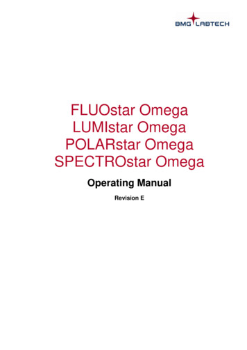
5O4O3O6O 7O 8OMPH9O1OO1OO12O2O1O13OO14OOMEGA KUSTOMINSTRUMENTSWiring Multiple GaugesAbove is an example of wiring a grouping of gauges together. The number one thing toremember is to commonize the basic three connections (power, ground, lights) and thenrun the sender wires. To simplify things even further, you can jump the lamp ground to thegauge ground. Use a minimum of 20 gauge stranded automotive grade wire.Wire the lighting to the stock dash lights unless you are using LED bulbs, then wire them tothe parking lamp circuit. An LED dimmer will be required to dim LED lights.When installing, you must use the matching senders provided. OE senders for pressureand temperature will not operate the gauges properly. You may use an OE sender for fuellevel when using a matching gauge. See chart on next page for more information on OEsender ranges.16Need Tech Help? Just call 800.979.0122
Omega Avant GaugesSenders and SignalsSenders are the part of the gauge system that send a signal to the gauge to be read,and then displayed on the dial face. There are four types of senders, resistance basespressure, temperature and level (fuel), voltage input pressure transducers, and pulsedspeed inputs.Temperature Senders:Signal type is resistance to ground. Resistance DECREASES as temperature rises. Alladvanced feature temperature gauges use a High-Match temperature sender. Thesender will read between 450-500 ohms at room temperature. Both low and high readgauges use the same sender.Pressure Senders:Pressure senders are resistance to ground signal. All of our pressure senders are 240-33ohm, 0-100 PSI regardless of the pressure range.Pressure Transducers:Pressure transducers send a voltage signal to the gauge to be read. Typically a linear.5V-4.5V signal can be read by any transducer gauge. There are typically 3 wires to thetransducer, signal, ground and 5V power (from the gauge or module).Fuel Level Senders:Fuel level Senders are also resistance to ground. A float arm rotates on a rheostat in thefuel tank and changes the resistance as the float arm moves. This is also available in atube type sender. The ranges can vary depending on the OE manufacturer. You ALWAYSneed to match the fuel gauge to the sender. We offer a universal fit 240-33 ohm and0-90 ohm unit for aftermarket applications. The senders are universal and mount fromthe top of the tank and have a universal 5-hole flange. These are not intended toreplace the stock sender for the tank which was specially manufactured for that tanksize/shape/orientation. Use a stock ender if at all possible to make things easier onyourself.TypeSW/UNIVGM LateGM EarlyFord EarlyFord LateGM nge E/F240-330-900-3073-1020-15040-250See our full inventory at SpeedwayMotors.com17
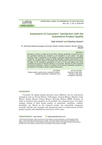
5O4O3O6O 7O 8OMPH9O1OO1OO12O2O1O13OO14OOMEGA KUSTOMINSTRUMENTSMechanical SpeedometerMechanical speedometers operate from a mechanical drive cable connected directly tothe transmission or transfer case. The drive ratio is 1:1 and cannot be altered. To changethe calibration, the cable drive gear in the transmission must be changed, a variety ofgears with different tooth counts are available for this purpose.194 BulbSocketLampGround (-)LampPower ( )5/8-18 Cable104x.104 Drive Tang(Universal Aftermarket)18M5x.8mmStudNeed Tech Help? Just call 800.979.0122
Omega Avant GaugesProgrammable Tachometer WiringStandalone tachometers with AMP plugs are incandescent perimeter, backlit or LEDbacklit. Incandescent bulbs will be in the access holes installed into the circuit board.DIP-switch settings are not required on tachometers. 3-3/8" and 4-3/8" are the sameconfiguration.PINColorFunction1RED12V Switched 1A*Aux Input*2GR/YEL3ORANGENot Used4YELLOW*Aux Input 2*5TANNot Used6WHITELighting7BLACKGround8VIOLETTach Signal9GREYNot Used10BLUENot Used11GREENNot Used12BROWN*Remote Button** Not used on tachometerwithout OLED display19
5O4O3O6O 7O 8OMPH9O1OO1OO12O2O1O13OO14OOMEGA KUSTOMINSTRUMENTSTachometer SignalsIgnition Coil: Even today the most common ignition source is the traditional coil.(incorporates the coil and either points or electronic ignition all into the distributor.)Use the negative side of the coil when using a distributor style with traditional points orelectronic ignition. The signal is a high-voltage pulsed signal.Coil On Plug (COP) is essentially the same as a traditional coil with the exception ofeach cylinder having its own individually fired coil. This setup is used in conjunction withPCMs. If you use the trigger on a COP the tachometer should be set to 1 cylinder (2PPR)operation.AFTERMARKET HIGH ENERGY IGNITION SYSTEMAftermarket distributors "MSD" boxes, CDI, etc. ALWAYS HAVE TACH OUTPUT.DO NOT CONNECT TO THE COIL OR DAMAGE WILL RESULT. These types ofsystems have multiple high energy signals going to the coil and will produceovervoltage feedback damaging to the tachometer. This is why there is aseparate tach signal.GM PCM have an open collector signal tach output, consult your PCM documentation forexact PIN. You will need a 10K-ohm pullup resistor to change the open collector signal to asquare wave (see diagram ). This is installed to pull up the signal between the power andtach signal from the PCM. All GM PCMs output a 4-cylinder signal regardless of numberof cylinders or if it is gas or diesel.Crank Trigger type generates an AC sinewave signal by using a magnetic sender to"count" the number of teeth. Your NVU tachometer may require bypassing of the internalfilter call for more information. You will also need to calibrate the PPR (programmablemodels with OLED) (pulse per revolution) to the number of teeth or magnets on theflywheel.Alternator "W" Terminal also outputs an AC sinewave like the above crank trigger, areference tachometer is the best way to determine the exact RPM, then the tach can beproperly calibrated by setting the PPR (programmable models with OLED).20
Omega Avant GaugesProgrammable Tachometers Without OLED ScreenProgrammable tachometers feature easy to set up operation and are ready to run on4-cycle engines. With 1 (COP Coil On Plug), 4, 6 and 8 cylinder settings. Your tachometercan be pre-set to any pulse configuration (contact the factory for more details). Signalstypically are from the negative side of the coil, CDI box or PCM (computer). You mayrequire a pull-up resistor on GM PCMs, see later in this book. All tachometers are shippedfrom the factory set at 8 cylinder selection and signal filter off (most applications).Cylinder SelectionPower down the unit, settings will not take effect until the power is cycled off. Removethe black cover on the back of the unit. The first 3 DIP switches are for setting the numberof cylinders, the last one adjusts the filtering (next segment). Follow the chart and selectthe proper settings for your application. 1 cylinder is used for COP (Coil On Plug) ignitionswhere a separate tachometer signal is not available. Use a small pointer object to changethe switch settings if required. Check that the switch is fully engaged in the "ON" or "OFF"position. If cylinder setting is not available for your application, contact the factory andyour setting can be custom programmed for a nominal F8OFFONON10OFFONOFF12OFFOFFONFilter SettingsTachometers are shipped with the signal filter off (DIP-Switch #4 in the OFF position). Thiswill be appropriate for most applications that use a 12V square wave or coil signal. To useon a lower power signal, with the power off, place switch #4 in the "ON" position.For additional filtering options, contact the factory. We can bypass the internal filter andadjust to suit your custom input.21
5O4O3O6O 7O 8OMPH9O1OO1OO12O2O1O13OO14OOMEGA KUSTOMINSTRUMENTSSenders and SignalsSpeedometer Signals:All speedometers will accept a speed signal from just about any speed signal senderor PCM output. Below is a brief description of each signal type followed by a chart forinput DIP-Switch settings for optimum use. NOTE: if you have a speedometer that isfunctioning but may have erratic movement at certain speeds, experimentation withswitching DIP-Switch 1 and 2 may help with stabilizing the pointer readout. This will notcause any damage when properly reading from a speed signal source.Hall Effect Sender:This type of sender is identified by having 3 wires. The sender uses power and ground tocreate a square wave signal which is alternating positive and negative. The speedometerreads each alternating "pulse." These are commonly used on cable-output senders whichreplace the traditional cable on the transmission.AC Sine Wave Sender:Commonly referred to as a pulse generator. This unit is identified by 2 wires, one is aground, one is the signal. This type of sender also is commonly used to replace the cableon the transmission. This type creates an AC sine wave signal, which has 2 components:amplitude and frequency. The sender generates an AC voltage, typically between 8-18volts which is the strength, or amplitude. The rate that the voltage alternates (AC like inyour home) is the frequency, which is the "pluses" the speedometer reads.Magnetic Pickup:This sender is the exact same as the AC sine wave pulse generator above but it isusually installed in the transmission at the factory. The sender or "pickup" bolts into thetransmission and a reluctor (toothed) ring spins b
Omega Avant Gauges 5 Use a minimum of 20 gauge insulated, stranded wire. All connections should be onnected with a crimp connection or solder and heat shrink.c eep speed signal wire(s) away from potential "noise" sources like ignition wires, K ach signal wires, fan motors, pumps, etc.t Studded speedometers use #8 studs.