Transcription
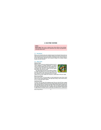
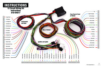
INSTRUCTIONSLeft High BeamHornPower Antenna48Left Front ParkOil SendingCoil Pos45Tachometer551Headlight Power5645Tachometer58Alt Power44Alt ExcitorRear of Vehicle5140Fuel GaugeInstrumentsand Dash5972Temp SenderLeft Low Beam2816Right Signal IndLeft Front Park2473High Beam IndLeft Front Signal4814Left Signal IndRight Front Signal1556Oil SendingFuse Panel & Frontof Vehicle179Gauge PowerFan4712 Circuit Wiring KitInstructions910-6401735Left Tail ParkIgn Switch StartThird BrakeLeft Rear TurnRight Rear TurnLeft Tail Park161714152632293130334019202135 2016, Speedway Motors, Inc.52Fuel Gauge27Ign Switch Power25Ign Switch Coil20Ign Switch Acc21Ign Switch Ign18Ign Switch StartHazard19Horn SwitchTurn Flasher24Left Front SignalLeft Rear Turn28Left Signal IndRight Rear Turn73Right Front SignalBrake Switch22Right Signal IndThird Brake Light71Fan GroundLeft Low Beam7Wiper PowerLeft High Beam3AC Heat PowerHigh Beam Ind51Power AntennaDimmer Power6Radio Constant PowerSolenoid Power3218Brake SwitchTemp Sending7211Brake Switch PowerIgnition and Lights5022Dimmer PowerChoke Power1910-64017 6/2016
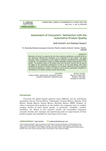
INSTRUCTIONS12 Circuit Wiring KitInstructions910-64017Fuse PanelWIRE #COLORPRINTINGWIRE #COLORPRINTING51PurplePower Antenna44WhiteAlt Excitor47GrayFan58RedAlt Power17Dark BlueRight Front Signal72Light GreenTemp Sending15Light BlueLeft Front Signal50RedChoke Power48BrownLeft Front Park32PurpleIgn Switch Start24TanLeft Low Beam52RedSolenoid PowerPinkCoil Pos28Light GreenLeft High Beam5559Dark GreenHorn45PurpleTachometer56Light BlueOil SendingThis fuse panel is designed to be mounted undera dash away from the elements.Front of vehicle connectionsFan17Right Front Signal15Left Front Signal48Left Front Park24Left Low Beam28Left High Beam59HornAlt Excitor44Alt Power58Tachometer45Oil Sending56HEISTARTER55Coil PosRESISTOR52 32-Solenoid PowerR S50Ign Switch StartBATTERYPoints Type Ignition72Temp SendingRun the purple ignition switch start wire (32) tothe S terminal on your starter.Run the red solenoid power (52) to the batteryterminal on your starter.NOTE: You MUST install the fusible link wire[69] inline at starter. FAILURE TO INSTALL THEFUSIBLE LINK VOIDS ANY AND ALL WARRANTYON THIS HARNESS.47Run the tan left low beam (24) wire to the lowside of your left front headlight(SELECT STYLE)51Run the tan right low beam (53) wire to the lowside of your right front headlightCHARGING SYSTEMSChoke PowerRun the red choke power (50) wire to thepositive terminal on your electric choke.Run the green temperature sender (72) wire tothe temperature sending unit.68Low Beam6658Run the light green right high beam (54) wire tothe high side of your right front headlightGENERATORFLDRun the light green left high beam (28) wire to thehigh side of your left front headlight1 2ARMRun the brown right front park (49) wire to thelow side of your right front dual filament turnsignal bulb.LATEBAT ARM FLDRun the brown left front park (48) wire to the lowside of your left front dual filament turn signalbulb.Run the pink coil positive (55) wire to either thebattery side of a GM HEI distributor or the ballastresistor on a points style distributor. If you’reusing an aftermarket ignition modules pleasefollow its instructions for specific directionsRun the purple tachometer (45) wire to the tachterminal on a GM HEI distributor, the negativeside of the coil, or to a tach connector on anaftermarket ignition module.67Power Antenna58Run the light blue left front turn signal (15) wire tothe high side of your left front dual filament turnsignal bulb.Run the light blue oil sending unit (56) wire tothe oil pressure sending unit. If you’re using amechanical oil pressure gauge this wire can betrimmed out of the harness.58Run the dark blue right front turn signal (17) wireto the high side of your right front dual filamentturn signal bulb.High BeamEARLY44Run the purple power antenna wire (51) to thepositive connection on your power antenna unit.Ground44Run the dark green horn feed (59) wire to thepositive connection on your horn.Run the red alternator power (58) wire toterminal 2 on your GM alternator. If you’re usinga one wire alternator this wire will run to thecharging post on the alternator.NOTE: If using an alternator with 80 ampsor more, you must use the bypass wire [75]included with harness. Connect the bypass wireto the red alternator post then to starter solenoidwhere the positive battery cable connects.Headlight ConnectionF 2 3 4Run gray [47] to fan positive wire. Run fanground wire- to chassis ground. Black (71) is fanrelay ground and routes to temperature sensor inengine, toggle switch going to ground, or directto ground if you want fan to run continuous whenkey is in run position.Run the white alternator exciter (44) wire tothe 1 terminal on your GM alternator. If you areusing a one wire alternator this wire can betrimmed out of harness. - COILDIST 2016, Speedway Motors, Inc.2910-64017 6/2016
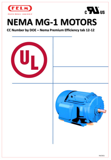
Ignition SwitchConnection KitGM Column Mount910-64027-3INSTRUCTIONS12 Circuit Wiring KitInstructions910-64017BATIGNSTACCGround[during crank only]Spare IgnitionIgn Switch Power33Ign Switch Start32Ign Switch Acc31Ign Switch Coil30Ign Switch Ign29Horn Switch26Left Front Signal15Left Signal Ind14WIRE #COLORPRINTING33RedIgn Switch PowerRight Front Signal1732PurpleIgn Switch StartRight Signal Ind1631OrangeIgn Switch Acc30PinkIgn Switch Coil29BrownIgn Switch Ign26Light GreenHorn Switch15Light BlueLeft Front Signal14Light BlueLeft Signal Ind17Dark BlueRight Front Signal16Dark BlueRight Signal Ind27BrownHazard25PurpleTurn Flasher20YellowLeft Rear Turn21Light GreenRight Rear Turn18White19COLUMN MOUNTED IGNITIONSWITCH[GM STYLE]Hazard25Left Rear Turn20Right Rear Turn21Third Brake LightStarterBatteryIgnitionOnce the wires are installed in their appropriate cavity,the white plug will be plugged into the switch first usingthe black connector to secure it in place. Even if thereare no wires in the black pigtail plug in the connector toretain the white one.27Turn FlasherBrake SwitchAccessoryUse supplied harness plugs and the appropriate wiringdiagram for your switch to determine which wires willgo where. GM used multiple style switches with differentwiring pin outs; please verify which style you need. Ourcavity diagram is a generic one that is common for mostGM vehicles.DIMMER SWITCHThe left bottom wire will run to your low beam controlcircuit [tan wire #24]18The bottom right wires will run your high beam controlcircuit [green wires #28 and 73]1928Left High BeamOrangeThird Brake Light7324TanLeft Low BeamHigh Beam Ind28Light GreenLeft High Beam22Dimmer Power73Light GreenHigh Beam Ind22Light BlueDimmer PowerHigh Beam IndBrake SwitchThe top wire will run to your dimmer switch [LightBlue wire #22]Dimmer PowerLeft High BeamLeft Low BeamLeft Low Beam24 2016, Speedway Motors, Inc.3910-64017 6/2016
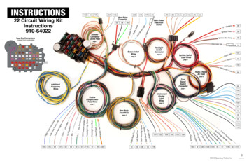
INSTRUCTIONS12 Circuit Wiring KitInstructions910-64017721809SpeedometerFuel63120 130110Volts5400 10 20 30 400860 7 0 90 1005Oil PressTachometerTem pSymbol for GroundHIGH BEAM IN DRedRadio Constant Power51PurplePower Antenna3BlackAC Heat Power7Dark BlueWiper Power14Dark BlueLeft Signal Ind73Light GreenHigh Beam Ind16Dark BlueRight Signal Ind40PinkFuel Gauge45PurpleTachometer56Light BlueOil Sending72Dark GreenTemp Sending9RedGauge Power62BrownInstrument panel lights148352211186513771Instrument Panel Lights6Gauge PowerBrake SwitchTemp SenderWhiteOil Sending18TachometerBrake Switch PowerFuel GaugeOrangeDRight Signal Ind11RIGHT TURN INHigh Beam IndDimmer PowerDLeft Signal IndLight BlueFan Ground22LEFT TURN INWiper PowerLeft Tail ParkAC Heat PowerBrownPower Antenna35Radio Constant PowerLeft Front ParkBrake SwitchHeadlight PowerBrake Switch PowerRedBrownDimmer Power148Left Tail ParkPRINTINGLeft Front ParkCOLORHeadlight PowerWIRE #14731640455672962 2016, Speedway Motors, Inc.4910-64017 6/2016
INSTRUCTIONSHEADLIGHT/DIMMER SWITCH CONNECTIONS12 Circuit Wiring KitInstructions910-6401722Headlight/Dimmer Power62Dash LightsTURN SIGNAL SWITCH CONNECTIONS(Optional)18PNL25M2027If you are using a later 1975 and on column we have included aconnector to convert over to the required style. The columns use thesame pin out locations making the swap easy; please follow the wiringtable below to install the adapter plug on a column./1 921This kit was designed to function with a factory GM style switch andcolumn plug. It plugs into the 3-7/8” plug found on GM columns from1969-1974. It is found on a majority of after market columns includingSpeedway’s Tilt Columns such as p/n t GreenHorn Relay GroundHorn button ground to the horn relay trigger14/15HLight BlueLeft Front TurnFeeds the left front turn lamp bulb high filament and the left turndash indicator lamp16/17JDark BlueRight Front TurnFeeds the right front turn lamp bulb high filament and the rightturn dash indicator lamp27KBrownTurn Sw-Hazard4 way hazard power feed wire from the Hazard flasher “L”terminal25LPurpleTurn Switch FeedTurn signal power feed wire from the Turn signal flasher “L”terminal20MYellowLeft Rear TurnFeeds the left rear turn and brake lamp bulb high filament21NDark GreenRight Rear TurnFeeds the right rear turn and brake lamp bulb high filamentWhite(18)/Orange(19)Brake Switch(18)Third brake light (19)Power feed wire from the output side of the brake switchIMPORTANTDCONNECTIONPLF Park35LR Tail /Park1Battery14/15WIRE #18/1948DISCLAIMER In an effort to offer our customers the low prices, quick service and greatvalue, Speedway Motors reserves the right to change suppliers, specifications, colors,prices, materials. Each of the previous items is subject to change without notice. Speedwayis not responsible for any typographical errors or misinterpretations. Quantities are limitedon some items.WARRANTY DISCLAIMER The purchaser understands and recognizes that racing parts,specialized street rod equipment, and all parts and services sold by Speedway Motors, Inc.are exposed to many and varied conditions due to the manner in which they are installed5and used. Speedway Motors, Inc. makes no warranties, either express or implied, includingany warranty of merchantability or fitness for a particular purpose other than those containedin its current catalog with respect to the goods identified on the face of the invoice. There isno warranty expressed or implied as to whether the goods sold hereby will protect purchaseror ultimate user of such goods from injury or death. Speedway Motors assumes no liabilityafter this period.DAMAGE CLAIMS Always inspect your package upon delivery. Inspect all packages in thepresence of the delivery driver. The driver must note any damage. Ask the driver the Carrier’sprocedures for handling damage claims. You must hold the original box, packing materialand damaged merchandise for inspection or the carrier will not honor the claim. NotifySpeedway Motors customer service department for instructions on returning damagedgoods. Speedway is not responsible if no notification is given within 5 days of receipt.RETURNS Speedway wants you to be satisfied with your purchase. If within 30 days afteryou receive your shipment you are not satisfied, you may return the item for refund orexchange. All exchanged or returned merchandise must be in original factory condition5with no modifications or alterations. Returned merchandise must include all packagingmaterials, warranty cards, manuals, and accessories. If the items being returned need tobe repackaged there will be a re-packing charge. Re-pack the item in a sturdy5 box andinclude a copy of your invoice and complete the form on the back of the invoice. You mustship orders back PRE-PAID. WE DO NOT ACCEPT COD SHIPMENTS. All exchanges needto have reshipping charges included. Items that are returned after 30 days are subject to15% restocking charges. All fiberglass returned will have 15% restocking charge. No returnson electrical parts, video tapes, and books. Absolutely no returns on special order or closeout merchandise.FREE CATALOGS Speedway Motors offers FREE catalogs for Race, Street, Sprint andMidget, Sport Compact and Pedal Car restoration.**Some items are not legal for sale or use in California on pollution controlled motor vehicles.These items are legal in California for racing vehicles only which may never be used upon ahighway.SHORTAGES Always check the contents of your delivery to insure all the parts that youordered were received. Please read the invoice. Double check all packing materials, smallitems may be wrapped inside with these products. Shortages may occur from damage tothe box, so save all packing materials. Inspect the box for holes that would allow parts to fallout. If you are missing any item[s] be sure to check your invoice for back orders or canceleditems before calling the customer service department. If Speedway has to split a shipment5into multiple boxes, packages may be delivered on different days. You need to contact thecustomer service department within 5 days of delivery to assure the prompt replacement.Speedway Motors assumes no liability after this period.REFUSALS All refused COD customers will be billed a 15% restocking charge plus freightto and from the destination! If you have questions please contact Speedway’s customerservice department.WARRANTY CLAIMS If an item has a manufacturer’s warranty as being free from defectswe will exchange only. If the item has been used and you are requesting warranty work,this may take up to 30 days as warranty work is done by the manufacturer NOT SpeedwayMotors. If you have any questions please contact customer service.Speedway Motors Inc.,P.O. Box 81906 Lincoln, NE 68501402-323-3200www.SpeedwayMotors.com 2016, Speedway Motors, Inc.5910-64017 6/2016
WARRANTY DISCLAIMER The purchaser understands and recognizes that racing parts, specialized street rod equipment, and all parts and services sold by Speedway Motors, Inc. are exposed to many and varied conditions due to the manner in which they are installed5 and used. Speedway Motors, Inc. makes no warranties, either express or implied, including